engine JEEP GLADIATOR 2023 Owner's Manual
[x] Cancel search | Manufacturer: JEEP, Model Year: 2023, Model line: GLADIATOR, Model: JEEP GLADIATOR 2023Pages: 448, PDF Size: 17.37 MB
Page 58 of 448
56GETTING TO KNOW YOUR VEHICLE
SECURITY
It is advised to erase all channels before you sell or
turn in your vehicle.
To do this, push and hold the two outside buttons
for 20 seconds until the indicator flashes. Note
that all channels will be erased. Individual
channels cannot be erased.
The HomeLink® Universal Transceiver is disabled
when the Vehicle Security system is active.
NOTE:The universal garage door opener only operates
when the engine is running for security reasons
associated with removable tops and doors.
TROUBLESHOOTING TIPS
If you are having trouble programming
HomeLink®, here are some of the most common
solutions:
Replace the battery in the garage door opener
hand-held transmitter.
Push the LEARN button on the garage door
opener to complete the training for a rolling code.
Did you unplug the device for programming and
remember to plug it back in? If you have any problems, or require assistance,
please call toll-free 1-800-355-3515 or, on the
Internet at HomeLink.com for information or
assistance.
EXTERIOR LIGHTS
HEADLIGHT SWITCH
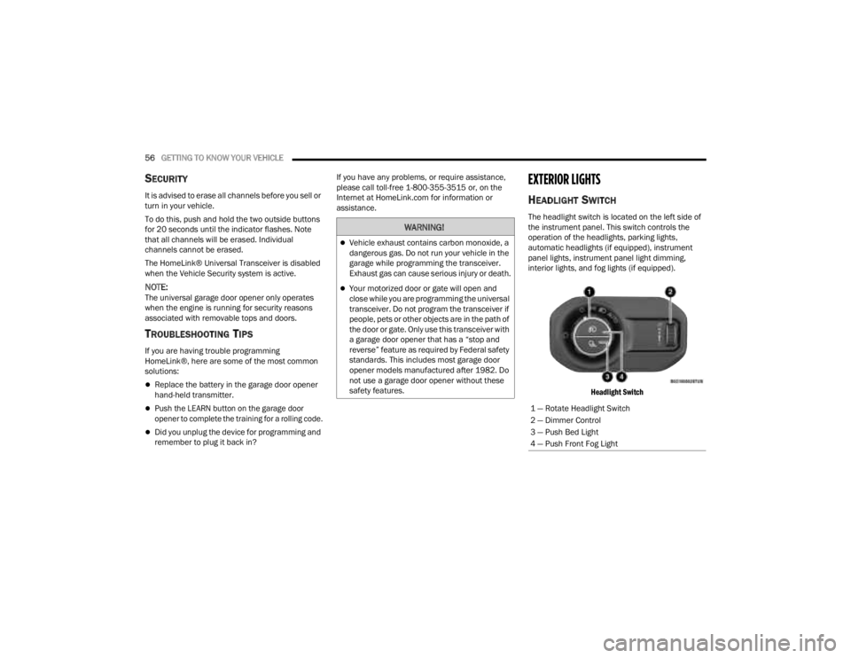
The headlight switch is located on the left side of
the instrument panel. This switch controls the
operation of the headlights, parking lights,
automatic headlights (if equipped), instrument
panel lights, instrument panel light dimming,
interior lights, and fog lights (if equipped).
Headlight Switch
WARNING!
Vehicle exhaust contains carbon monoxide, a
dangerous gas. Do not run your vehicle in the
garage while programming the transceiver.
Exhaust gas can cause serious injury or death.
Your motorized door or gate will open and
close while you are programming the universal
transceiver. Do not program the transceiver if
people, pets or other objects are in the path of
the door or gate. Only use this transceiver with
a garage door opener that has a “stop and
reverse” feature as required by Federal safety
standards. This includes most garage door
opener models manufactured after 1982. Do
not use a garage door opener without these
safety features.
1 — Rotate Headlight Switch
2 — Dimmer Control
3 — Push Bed Light
4 — Push Front Fog Light
23_JT_OM_EN_USC_t.book Page 56
Page 60 of 448
58GETTING TO KNOW YOUR VEHICLE
AUTOMATIC HIGH BEAM HEADLAMP
C
ONTROL — IF EQUIPPED
The Automatic High Beam Headlamp Control
system provides increased forward lighting at night
by automatically controlling the high beams
through the use of a camera mounted on the
vehicle’s header. This camera detects vehicle
specific light and automatically switches from high
beams to low beams until the approaching vehicle
is out of view.
NOTE:
The Automatic High Beam Headlamp Control
can be turned on or off by selecting “ON” under
“Auto Dim High Beams” within your Uconnect
Settings Ú page 215, as well as turning the
headlight switch to the AUTO position and
placing the multifunction lever in the high beam
position.
Broken, muddy, or obstructed headlights and
taillights of vehicles in the field of view will
cause headlights to remain on longer (closer to
the vehicle). Also, dirt, film, and other obstruc -
tions on the windshield or camera lens will
cause the system to function improperly.
FLASH-TO-PASS
The Flash-To-Pass feature will illuminate the high
beam headlights temporarily to signal another
vehicle of a passing occurrence. Pull and hold the
Multifunction Lever to activate the Flash-To-Pass
feature. When the lever is released, the
Flash-To-Pass feature will deactivate.
AUTOMATIC HEADLIGHTS — IF EQUIPPED
The Automatic Headlight System will turn the
headlights on or off according to ambient light
levels. To turn the system on, rotate the headlight
switch clockwise to the last detent for automatic
headlight operation. When the system is on, the
headlight time delay feature is also on. This means
the headlights will stay on for up to 90 seconds
(programmable through the Uconnect Settings
Ú
page 215) after you place the ignition into the
OFF position. To turn the automatic system off,
move the headlight switch out of the AUTO position.
NOTE:The engine must be running before the headlights
will come on in the automatic mode.
LIGHTS-ON REMINDER
If the headlights or parking lights are left on after
the ignition is placed in the OFF position, the vehicle
will chime when the driver’s door is opened.
FRONT FOG LIGHTS — IF EQUIPPED
The Front Fog Lights are located on the front of the
vehicle below the headlights. When activated,
these lights add illumination directed at the driving
surface to aid in poor visibility conditions.
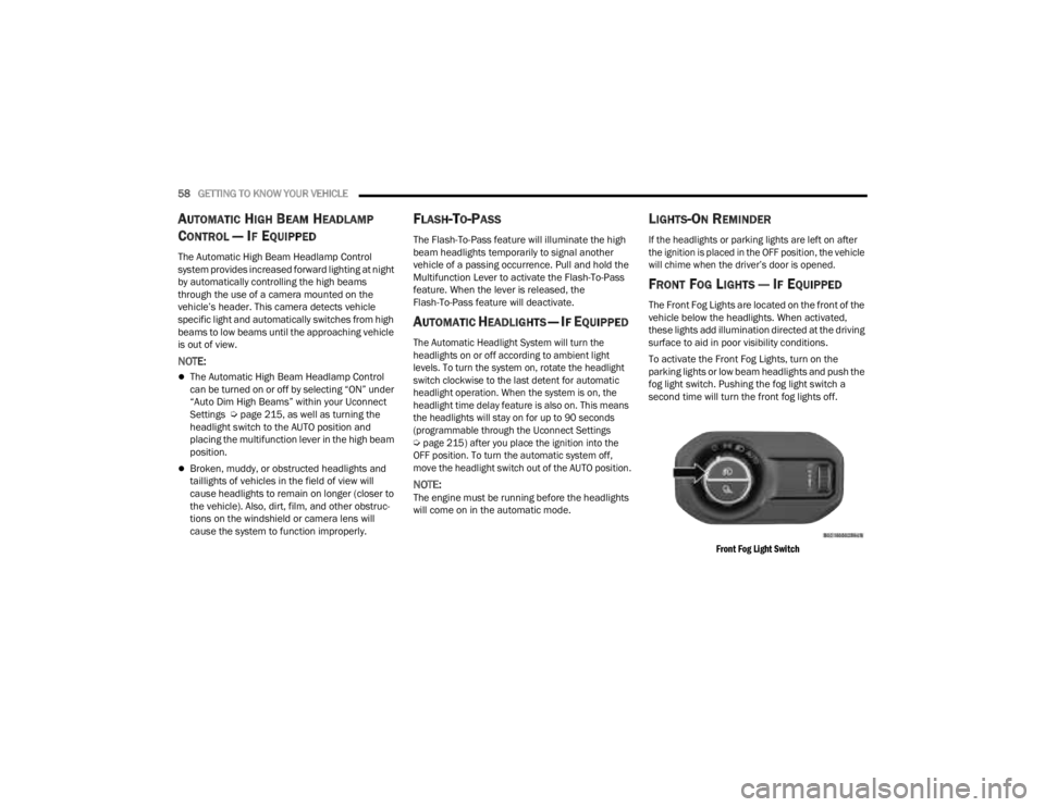
To activate the Front Fog Lights, turn on the
parking lights or low beam headlights and push the
fog light switch. Pushing the fog light switch a
second time will turn the front fog lights off.
Front Fog Light Switch
23_JT_OM_EN_USC_t.book Page 58
Page 63 of 448

GETTING TO KNOW YOUR VEHICLE61
Rotate the end of the lever upward to the first
detent past the intermittent settings for low-speed
wiper operation. Rotate the end of the lever
upward to the second detent past the intermittent
settings for high-speed wiper operation.
Intermittent Wipers
Use the intermittent wiper when weather
conditions make a single wiping cycle, with a
variable pause between cycles, desirable. Rotate
the end of the lever to the first detent position for
one of four intermittent settings. The delay cycle
can be set anywhere between 1 to 18 seconds.
NOTE:The wiper delay times depend on vehicle speed. If
the vehicle is moving less than 10 mph (16 km/h),
delay times will be doubled. Windshield Washers
To use the washer, pull the lever toward you and
hold until desired spray is reached. If the lever is
pulled while in the delay range, the wiper will start
and continue to operate for two or three wipe
cycles after the lever is released. Then, the
intermittent interval previously selected will
resume.
If the lever is pulled while in the off position, the
wipers will operate for two or three wipe cycles.
Then, the wipers will turn off.
NOTE:As a protective measure, the washer will stop if the
switch is held for more than 20 seconds. Once the
switch is released the washer will resume normal
operation.
Mist
Push upward on the wiper lever to activate a single
wipe to clear off-road mist or spray from a passing
vehicle. As long as the lever is held up, the wipers
will continue to operate.
NOTE:The mist feature does not activate the washer
pump; therefore, no washer fluid will be sprayed on
the windshield. The washer function must be used
in order to spray the windshield with washer fluid.
For information on wiper care and replacement,
see Ú
page 374.
CLIMATE CONTROLS
The Climate Control system allows you to regulate
the temperature, air flow, and direction of air
circulating throughout the vehicle. The controls are
located on the touchscreen and on the instrument
panel below the radio.
CAUTION!
In cold weather, always turn off the wiper switch
and allow the wipers to return to the park
position before turning off the engine. If the
wiper switch is left on and the wipers freeze to
the windshield, damage to the wiper motor may
occur when the vehicle is restarted.
WARNING!
Sudden loss of visibility through the windshield
could lead to a collision. You might not see other
vehicles or other obstacles. To avoid sudden
icing of the windshield during freezing weather,
warm the windshield with the defroster before
and during windshield washer use.
2
23_JT_OM_EN_USC_t.book Page 61
Page 69 of 448

GETTING TO KNOW YOUR VEHICLE67
AUTOMATIC TEMPERATURE CONTROL
(ATC) — I
F EQUIPPED
Automatic Operation
1. Push the AUTO button on the faceplate, or the
AUTO button on the touchscreen on the
Automatic Temperature Control (ATC) Panel.
2. Next, adjust the temperature that you would like the system to maintain by adjusting the
driver and passenger temperature control
buttons. Once the desired temperature is
displayed, the system will achieve and
automatically maintain that comfort level.
3. When the system is set up for your comfort level, it is not necessary to change the
settings. You will experience the greatest
efficiency by simply allowing the system to
function automatically.
NOTE:
It is not necessary to move the temperature
settings for cold or hot vehicles. The system
automatically adjusts the temperature, mode,
and blower speed to provide comfort as quickly
as possible.
The temperature can be displayed in U.S. or
Metric units by selecting the U.S./Metric
customer-programmable feature within
Uconnect Settings Ú page 215. To provide you with maximum comfort in the
Automatic mode during cold start-ups, the blower
fan will remain on low until the engine warms up.
The blower will increase in speed and transition
into Auto mode.
Manual Operation Override
This system offers a full complement of manual
override features. The AUTO symbol in the front
ATC display will be turned off when the system is
being used in the manual mode.
CLIMATE VOICE COMMANDS
Adjust vehicle temperatures hands-free and keep
everyone comfortable while you keep moving
ahead.
Push the VR button on the steering wheel. After the
beep, say one of the following commands:
“
Set the driver temperature to 70 degrees ”
“Set the passenger temperature to 70 degrees ”
Did You Know:
Voice Command for Climate may
only be used to adjust the interior temperature of
your vehicle. Voice Command will not work to adjust
the heated seats or steering wheel if equipped.
OPERATING TIPS
NOTE:Refer to the chart at the end of this section for
suggested control settings for various weather
conditions.
Summer Operation
The engine cooling system must be protected with
a high-quality antifreeze coolant to provide proper
corrosion protection and to protect against engine
overheating. OAT coolant (conforming to
MS.90032) is recommended.
Winter Operation
To ensure the best possible heater and defroster
performance, make sure the engine cooling
system is functioning properly and the proper
amount, type, and concentration of coolant is
used. Use of the Air Recirculation mode during
Winter months is not recommended, because it
may cause window fogging.
Vacation/Storage
For information on maintaining the Climate Control
system when the vehicle is being stored for an
extended period of time, see Ú page 411.
2
23_JT_OM_EN_USC_t.book Page 67
Page 70 of 448
68GETTING TO KNOW YOUR VEHICLE
Window Fogging
Vehicle windows tend to fog on the inside in mild,
rainy, and/or humid weather. To clear the
windows, select Defrost or Mix mode and increase
the front blower speed. Do not use the
Recirculation mode without A/C for long periods,
as fogging may occur.
Outside Air Intake
Make sure the air intake, located directly in front of
the windshield, is free of obstructions, such as
leaves. Leaves collected in the air intake may
reduce airflow, and if they enter the air distribution
box, they could plug the water drains. In Winter
months, make sure the air intake is clear of ice,
slush, and snow.
Cabin Air Filter
The Climate Control system filters out dust and
pollen from the air. Contact an authorized dealer to
service your cabin air filter, and to have it replaced
when needed.
Stop/Start System — If Equipped
While in an Autostop, the Climate Control system
may automatically adjust airflow to maintain cabin
comfort. Customer settings will be maintained
upon return to an engine running condition.
Operating Tips ChartINTERIOR STORAGE AND EQUIPMENT
STORAGE
Glove Compartment
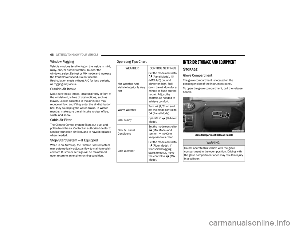
The glove compartment is located on the
passenger side of the instrument panel.
To open the glove compartment, pull the release
handle.
Glove Compartment Release Handle
WEATHER CONTROL SETTINGS
Hot Weather And
Vehicle Interior Is Very
Hot Set the mode control to
(Panel Mode),
(MAX A/C) on, and
blower on high. Roll
down the windows for a
minute to flush out the
hot air. Adjust the
controls as needed to
achieve comfort.
Warm Weather Turn (A/C) on and
set the mode control to
(Panel Mode).
Cool Sunny Operate in (Bi-Level
Mode).
Cool & Humid
Conditions Set the mode control to
(Mix Mode) and
turn on (A/C) to
keep windows clear.
Cold Weather Set the mode control to
(Floor Mode). If
windshield fogging
starts to occur, move
the control to (Mix
Mode).
WARNING!
Do not operate this vehicle with the glove
compartment in the open position. Driving with
the glove compartment open may result in injury
in a collision.
23_JT_OM_EN_USC_t.book Page 68
Page 80 of 448
78GETTING TO KNOW YOUR VEHICLE
(Continued)
POWER INVERTERS — IF EQUIPPED
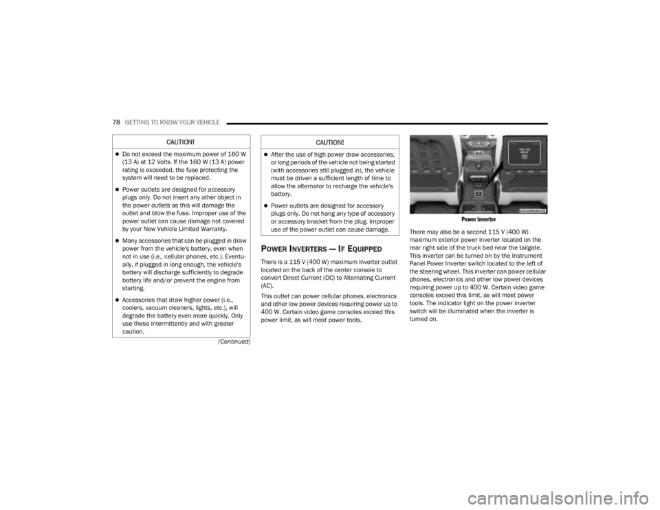
There is a 115 V (400 W) maximum inverter outlet
located on the back of the center console to
convert Direct Current (DC) to Alternating Current
(AC).
This outlet can power cellular phones, electronics
and other low power devices requiring power up to
400 W. Certain video game consoles exceed this
power limit, as will most power tools.
Power Inverter
There may also be a second 115 V (400 W)
maximum exterior power inverter located on the
rear right side of the truck bed near the tailgate.
This inverter can be turned on by the Instrument
Panel Power Inverter switch located to the left of
the steering wheel. This inverter can power cellular
phones, electronics and other low power devices
requiring power up to 400 W. Certain video game
consoles exceed this limit, as will most power
tools. The indicator light on the power inverter
switch will be illuminated when the inverter is
turned on.
CAUTION!
Do not exceed the maximum power of 160 W
(13 A) at 12 Volts. If the 160 W (13 A) power
rating is exceeded, the fuse protecting the
system will need to be replaced.
Power outlets are designed for accessory
plugs only. Do not insert any other object in
the power outlets as this will damage the
outlet and blow the fuse. Improper use of the
power outlet can cause damage not covered
by your New Vehicle Limited Warranty.
Many accessories that can be plugged in draw
power from the vehicle's battery, even when
not in use (i.e., cellular phones, etc.). Eventu -
ally, if plugged in long enough, the vehicle's
battery will discharge sufficiently to degrade
battery life and/or prevent the engine from
starting.
Accessories that draw higher power (i.e.,
coolers, vacuum cleaners, lights, etc.), will
degrade the battery even more quickly. Only
use these intermittently and with greater
caution.
After the use of high power draw accessories,
or long periods of the vehicle not being started
(with accessories still plugged in), the vehicle
must be driven a sufficient length of time to
allow the alternator to recharge the vehicle's
battery.
Power outlets are designed for accessory
plugs only. Do not hang any type of accessory
or accessory bracket from the plug. Improper
use of the power outlet can cause damage.
CAUTION!
23_JT_OM_EN_USC_t.book Page 78
Page 120 of 448
118GETTING TO KNOW YOUR INSTRUMENT PANEL
Use this QR code to access your
digital experience.
INSTRUMENT CLUSTER
D
ESCRIPTIONS
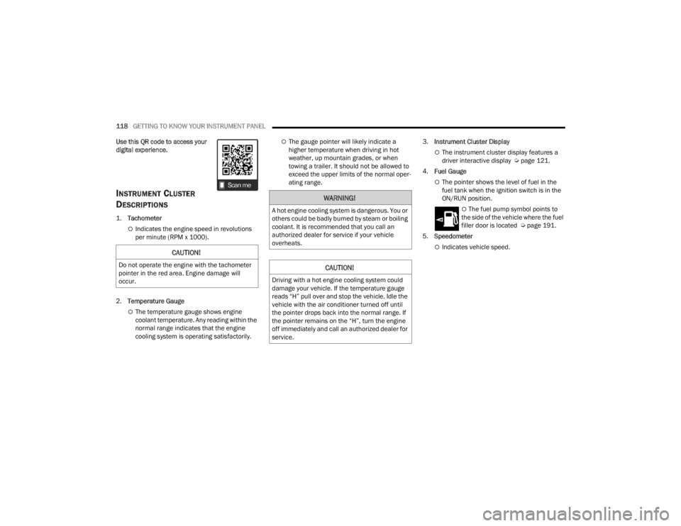
1.
Tachometer
Indicates the engine speed in revolutions
per minute (RPM x 1000).
2. Temperature Gauge
The temperature gauge shows engine
coolant temperature. Any reading within the
normal range indicates that the engine
cooling system is operating satisfactorily.
The gauge pointer will likely indicate a
higher temperature when driving in hot
weather, up mountain grades, or when
towing a trailer. It should not be allowed to
exceed the upper limits of the normal oper -
ating range. 3.
Instrument Cluster Display
The instrument cluster display features a
driver interactive display Ú page 121.
4. Fuel Gauge
The pointer shows the level of fuel in the
fuel tank when the ignition switch is in the
ON/RUN position.
The fuel pump symbol points to
the side of the vehicle where the fuel
filler door is located Ú page 191.
5. Speedometer
Indicates vehicle speed.CAUTION!
Do not operate the engine with the tachometer
pointer in the red area. Engine damage will
occur.
WARNING!
A hot engine cooling system is dangerous. You or
others could be badly burned by steam or boiling
coolant. It is recommended that you call an
authorized dealer for service if your vehicle
overheats.
CAUTION!
Driving with a hot engine cooling system could
damage your vehicle. If the temperature gauge
reads “H” pull over and stop the vehicle. Idle the
vehicle with the air conditioner turned off until
the pointer drops back into the normal range. If
the pointer remains on the “H”, turn the engine
off immediately and call an authorized dealer for
service.
23_JT_OM_EN_USC_t.book Page 118
Page 123 of 448
GETTING TO KNOW YOUR INSTRUMENT PANEL121
INSTRUMENT CLUSTER DESCRIPTIONS
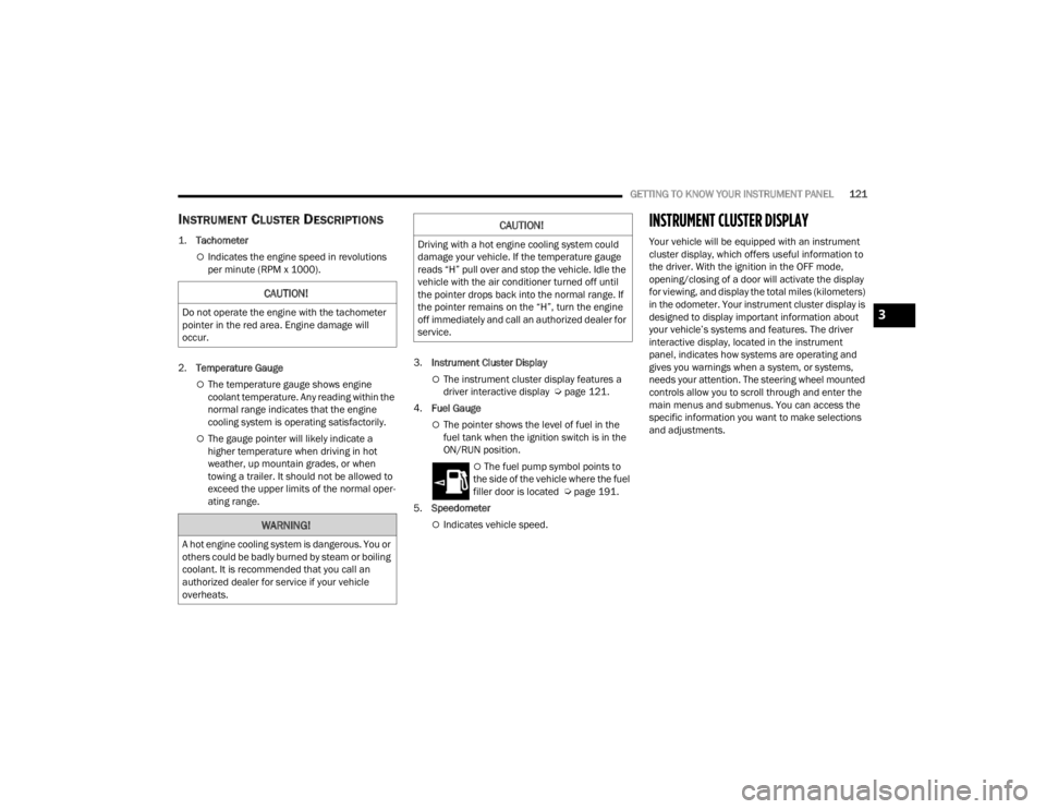
1.
Tachometer
Indicates the engine speed in revolutions
per minute (RPM x 1000).
2. Temperature Gauge
The temperature gauge shows engine
coolant temperature. Any reading within the
normal range indicates that the engine
cooling system is operating satisfactorily.
The gauge pointer will likely indicate a
higher temperature when driving in hot
weather, up mountain grades, or when
towing a trailer. It should not be allowed to
exceed the upper limits of the normal oper -
ating range. 3.
Instrument Cluster Display
The instrument cluster display features a
driver interactive display Ú page 121.
4. Fuel Gauge
The pointer shows the level of fuel in the
fuel tank when the ignition switch is in the
ON/RUN position.
The fuel pump symbol points to
the side of the vehicle where the fuel
filler door is located Ú page 191.
5. Speedometer
Indicates vehicle speed.
INSTRUMENT CLUSTER DISPLAY
Your vehicle will be equipped with an instrument
cluster display, which offers useful information to
the driver. With the ignition in the OFF mode,
opening/closing of a door will activate the display
for viewing, and display the total miles (kilometers)
in the odometer. Your instrument cluster display is
designed to display important information about
your vehicle’s systems and features. The driver
interactive display, located in the instrument
panel, indicates how systems are operating and
gives you warnings when a system, or systems,
needs your attention. The steering wheel mounted
controls allow you to scroll through and enter the
main menus and submenus. You can access the
specific information you want to make selections
and adjustments.
CAUTION!
Do not operate the engine with the tachometer
pointer in the red area. Engine damage will
occur.
WARNING!
A hot engine cooling system is dangerous. You or
others could be badly burned by steam or boiling
coolant. It is recommended that you call an
authorized dealer for service if your vehicle
overheats.
CAUTION!
Driving with a hot engine cooling system could
damage your vehicle. If the temperature gauge
reads “H” pull over and stop the vehicle. Idle the
vehicle with the air conditioner turned off until
the pointer drops back into the normal range. If
the pointer remains on the “H”, turn the engine
off immediately and call an authorized dealer for
service.
3
23_JT_OM_EN_USC_t.book Page 121
Page 124 of 448
122GETTING TO KNOW YOUR INSTRUMENT PANEL
INSTRUMENT CLUSTER DISPLAY
L
OCATION AND CONTROLS
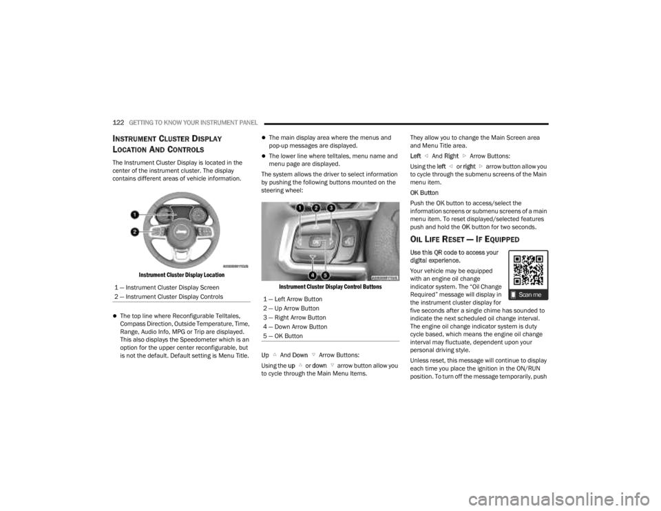
The Instrument Cluster Display is located in the
center of the instrument cluster. The display
contains different areas of vehicle information.
Instrument Cluster Display Location
The top line where Reconfigurable Telltales,
Compass Direction, Outside Temperature, Time,
Range, Audio Info, MPG or Trip are displayed.
This also displays the Speedometer which is an
option for the upper center reconfigurable, but
is not the default. Default setting is Menu Title.
The main display area where the menus and
pop-up messages are displayed.
The lower line where telltales, menu name and
menu page are displayed.
The system allows the driver to select information
by pushing the following buttons mounted on the
steering wheel:
Instrument Cluster Display Control Buttons
Up And Down Arrow Buttons:
Using the up or down arrow button allow you
to cycle through the Main Menu Items. They allow you to change the Main Screen area
and Menu Title area.
Left
And Right Arrow Buttons:
Using the left or right arrow button allow you
to cycle through the submenu screens of the Main
menu item.
OK Button
Push the OK button to access/select the
information screens or submenu screens of a main
menu item. To reset displayed/selected features
push and hold the OK button for two seconds.
OIL LIFE RESET — IF EQUIPPED
Use this QR code to access your
digital experience.
Your vehicle may be equipped
with an engine oil change
indicator system. The “Oil Change
Required” message will display in
the instrument cluster display for
five seconds after a single chime has sounded to
indicate the next scheduled oil change interval.
The engine oil change indicator system is duty
cycle based, which means the engine oil change
interval may fluctuate, dependent upon your
personal driving style.
Unless reset, this message will continue to display
each time you place the ignition in the ON/RUN
position. To turn off the message temporarily, push
1 — Instrument Cluster Display Screen
2 — Instrument Cluster Display Controls
1 — Left Arrow Button
2 — Up Arrow Button
3 — Right Arrow Button
4 — Down Arrow Button
5 — OK Button
23_JT_OM_EN_USC_t.book Page 122
Page 125 of 448

GETTING TO KNOW YOUR INSTRUMENT PANEL123
and release the OK button. To reset the oil change
indicator system (after performing the scheduled
maintenance), refer to the following procedure.
Oil Life Reset
1. Without pushing the brake pedal, place the ignition in the ON/RUN mode (do not start the
engine).
2. Navigate to "Oil Life" submenu in "Vehicle Info" in the instrument cluster display.
3. Push and hold the OK button until the gauge
resets to 100%.
Secondary Method For Oil Change Reset
Procedure
1. Without pushing the brake pedal, place the ignition in the ON/RUN position (do not start
the engine).
2. Fully press the accelerator pedal, slowly, three times within ten seconds.
3. Without pushing the brake pedal, place the ignition in the OFF position.
NOTE:If the indicator message illuminates when you start
the vehicle, the oil change indicator system did not
reset. If necessary, repeat this procedure.
OFF ROAD+ DISPLAY — IF EQUIPPED
When the Off Road+ button is pushed in the switch
bank, the Instrument Cluster Display will begin to
show messages related to the feature. Depending
on the Four Wheel Drive mode in use, the
messages will differ, and after five seconds, all
messages will clear from the display. The
messages are as follows:
2H: Off Road+ Unavailable, Shift to 4WD
4H: 4WD High Off Road+ Active
4L: 4WD Low Off Road+ Active
Adaptive Cruise Control (ACC) and Cruise Control
are not available when using Off Road+. If either
option is selected, a dedicated message will
display indicating that the features are not usable
concurrently. Messages are as follows:
4H: Cruise Control — Cruise Control Unavailable
in Off Road+
4H: Adaptive Cruise Control — Adaptive Cruise
Control (ACC) Unavailable in Off Road+
4L: Cruise Control — Cruise Control Unavailable
in 4WD Low
4L: Adaptive Cruise Control — Adaptive Cruise
Control (ACC) Unavailable in 4WD Low
NOTE:The behavior of Electronic Stability Control while in
Off Road+ varies depending on the 4WD status. If
the vehicle is in 4WD High, Traction Control is auto -
matically turned off. Also, holding the ESC OFF
button for five seconds will turn off ESC. In 4WD
Low, Electronic Stability Control automatically
shuts off regardless of the Off Road Status.
INSTRUMENT CLUSTER DISPLAY
S
ELECTABLE ITEMS
The instrument cluster display can be used to view
the following main menu items:
NOTE:Depending on the vehicles options, feature
settings may vary.
Speedometer Driver Assist —
If EquippedMessages
Vehicle Info Trip Info Screen Setup
Fuel Economy Stop/Start Audio
Off Road —
If Equipped
3
23_JT_OM_EN_USC_t.book Page 123