key JEEP GLADIATOR 2023 Owner's Manual
[x] Cancel search | Manufacturer: JEEP, Model Year: 2023, Model line: GLADIATOR, Model: JEEP GLADIATOR 2023Pages: 448, PDF Size: 17.37 MB
Page 71 of 448
GETTING TO KNOW YOUR VEHICLE69
Console Storage Compartment
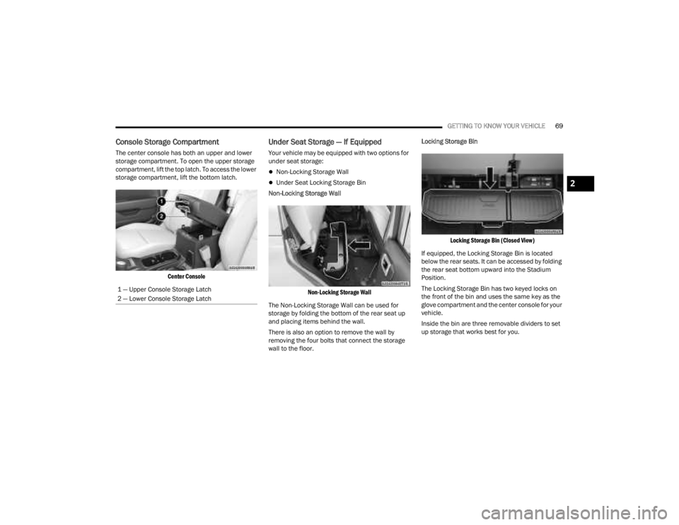
The center console has both an upper and lower
storage compartment. To open the upper storage
compartment, lift the top latch. To access the lower
storage compartment, lift the bottom latch.
Center Console
Under Seat Storage — If Equipped
Your vehicle may be equipped with two options for
under seat storage:
Non-Locking Storage Wall
Under Seat Locking Storage Bin
Non-Locking Storage Wall
Non-Locking Storage Wall
The Non-Locking Storage Wall can be used for
storage by folding the bottom of the rear seat up
and placing items behind the wall.
There is also an option to remove the wall by
removing the four bolts that connect the storage
wall to the floor. Locking Storage Bin
Locking Storage Bin (Closed View)
If equipped, the Locking Storage Bin is located
below the rear seats. It can be accessed by folding
the rear seat bottom upward into the Stadium
Position.
The Locking Storage Bin has two keyed locks on
the front of the bin and uses the same key as the
glove compartment and the center console for your
vehicle.
Inside the bin are three removable dividers to set
up storage that works best for you.
1 — Upper Console Storage Latch
2 — Lower Console Storage Latch2
23_JT_OM_EN_USC_t.book Page 69
Page 72 of 448
70GETTING TO KNOW YOUR VEHICLE
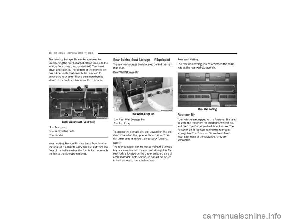
The Locking Storage Bin can be removed by
unfastening the four bolts that attach the bin to the
vehicle floor using the provided #40 Torx head
driver and ratchet. The bottom of the storage bin
has rubber mats that need to be removed to
access the four bolts. These bolts can then be
stored in the fastener bin below the rear seat.
Under Seat Storage (Open View)
Your Locking Storage Bin also has a front handle
that makes it easier to carry and pull out from the
floor of the vehicle when the four bolts that attach
the bin to the floor are removed.
Rear Behind Seat Storage — If Equipped
The rear wall storage bin is located behind the right
rear seat.
Rear Wall Storage Bin
Rear Wall Storage Bin
To access the storage bin, pull upward on the pull
strap located on the upper outboard side of the
right rear seat, and fold the seatback forward.
NOTE:The rear seatback can be locked using the vehicle
key to secure items in the rear wall storage bin. The
seat lock is located on the upper outboard side of
each seatback. Both seatbacks should be locked
to limit access to items behind seat. Rear Wall Netting
The rear wall netting can be accessed the same
way as the rear wall storage bin.
Rear Wall Netting
Fastener Bin
Your vehicle is equipped with a Fastener Bin used
to store the fasteners for the doors, windshield,
and hard top (if equipped) while not in use. The
Fastener Bin is located behind the rear seat
storage bin. The Fastener Bin contains foam
inserts for each of the fasteners; they are
removable.
1 — Key Locks
2 — Removable Bolts
3 — Handle1 — Rear Wall Storage Bin
2 — Pull Strap
23_JT_OM_EN_USC_t.book Page 70
Page 79 of 448
GETTING TO KNOW YOUR VEHICLE77
NOTE:Please refer to the information on the bottom of
the Jeep® wireless speaker for electrical and
safety information before installing or operating
the Jeep® wireless speaker. Directive 2014/53/EU Article 10 Obligations of
Manufacturers
2. Manufacturers shall ensure that radio
equipment shall be so constructed that it can be
operated in at least one Member State without
infringing applicable requirements on the use of
radio spectrum.
10. In cases of restrictions on putting in to service
or of requirements for authorization of use,
information available on the packaging shall allow
the identification of the Member States or the
geographical area within a Member State where
restrictions on putting into service or requirements
for authorization of use exist. The Commission may
adopt implementing acts specifying how to present
that information. Those implementing acts shall be
adopted in accordance with the advisory
procedure referred to in Article 45 (2).
The Bluetooth® word mark and logos are
registered trademarks owned by Bluetooth SIG,
Inc. and any use of such marks by FCA US LLC is
under license. Other trademarks and trade names
are those of their respective owners.
POWER OUTLETS
There is a 12 Volt (13 A) auxiliary power outlet that
can provide power for accessories designed for
use with the standard power outlet adapters.
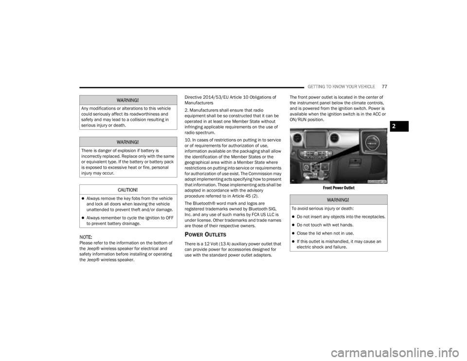
The front power outlet is located in the center of
the instrument panel below the climate controls,
and is powered from the ignition switch. Power is
available when the ignition switch is in the ACC or
ON/RUN position.
Front Power Outlet
WARNING!
Any modifications or alterations to this vehicle
could seriously affect its roadworthiness and
safety and may lead to a collision resulting in
serious injury or death.
WARNING!
There is danger of explosion if battery is
incorrectly replaced. Replace only with the same
or equivalent type. If the battery or battery pack
is exposed to excessive heat or fire, personal
injury may occur.
CAUTION!
Always remove the key fobs from the vehicle
and lock all doors when leaving the vehicle
unattended to prevent theft and/or damage.
Always remember to cycle the ignition to OFF
to prevent battery drainage.
WARNING!
To avoid serious injury or death:
Do not insert any objects into the receptacles.
Do not touch with wet hands.
Close the lid when not in use.
If this outlet is mishandled, it may cause an
electric shock and failure.
2
23_JT_OM_EN_USC_t.book Page 77
Page 81 of 448
GETTING TO KNOW YOUR VEHICLE79
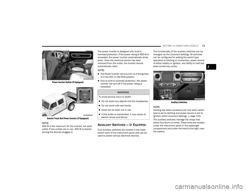
Power Inverter Switch (If Equipped)
Exterior Truck Bed Power Inverter (If Equipped)
NOTE:400 W is the maximum for the inverter, not each
outlet. If two outlets are in use, 400 W is shared
among the devices plugged in. The power inverter is designed with built-in
overload protection. If the power rating of 400 W is
exceeded, the power inverter automatically shuts
down. Once the electrical device has been
removed from the outlet, the inverter should
automatically reset.
NOTE:
The Power Inverter will only turn on if the ignition
is in the ACC or ON/RUN position.
Due to built-in overload protection, the power
inverter will turn off if the power rating is
exceeded.
AUXILIARY SWITCHES — IF EQUIPPED
Four auxiliary switches are located in the lower
switch bank of the instrument panel and can be
used to power various electrical devices.The functionality of the auxiliary switches can be
changed via the Uconnect Settings. All switches
can be configured for setting the switch type
operation to latching or momentary, power source
of either battery or ignition, and ability to hold last
state across key cycles.
Auxiliary Switches
NOTE:Holding last state conditions are met when switch
type is set to latching and power source is set to
ignition within Uconnect Settings Ú page 215.
The auxiliary switches manage the relays that
power four blunt cut wires. These wires are located
under the instrument panel in the passenger
compartment and under the hood to the right, near
the battery.
WARNING!
To avoid serious injury or death:
Do not insert any objects into the receptacles.
Do not touch with wet hands.
Close the lid when not in use.
If this outlet is mishandled, it may cause an
electric shock and failure.
2
23_JT_OM_EN_USC_t.book Page 79
Page 83 of 448
GETTING TO KNOW YOUR VEHICLE81
POWER WINDOWS — IF EQUIPPED
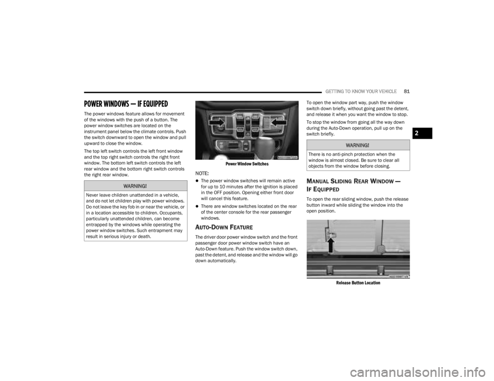
The power windows feature allows for movement
of the windows with the push of a button. The
power window switches are located on the
instrument panel below the climate controls. Push
the switch downward to open the window and pull
upward to close the window.
The top left switch controls the left front window
and the top right switch controls the right front
window. The bottom left switch controls the left
rear window and the bottom right switch controls
the right rear window.
Power Window Switches
NOTE:
The power window switches will remain active
for up to 10 minutes after the ignition is placed
in the OFF position. Opening either front door
will cancel this feature.
There are window switches located on the rear
of the center console for the rear passenger
windows.
AUTO-DOWN FEATURE
The driver door power window switch and the front
passenger door power window switch have an
Auto-Down feature. Push the window switch down,
past the detent, and release and the window will go
down automatically.To open the window part way, push the window
switch down briefly, without going past the detent,
and release it when you want the window to stop.
To stop the window from going all the way down
during the Auto-Down operation, pull up on the
switch briefly.
MANUAL SLIDING REAR WINDOW —
I
F EQUIPPED
To open the rear sliding window, push the release
button inward while sliding the window into the
open position.
Release Button Location
WARNING!
Never leave children unattended in a vehicle,
and do not let children play with power windows.
Do not leave the key fob in or near the vehicle, or
in a location accessible to children. Occupants,
particularly unattended children, can become
entrapped by the windows while operating the
power window switches. Such entrapment may
result in serious injury or death.
WARNING!
There is no anti-pinch protection when the
window is almost closed. Be sure to clear all
objects from the window before closing.
2
23_JT_OM_EN_USC_t.book Page 81
Page 102 of 448
100GETTING TO KNOW YOUR VEHICLE
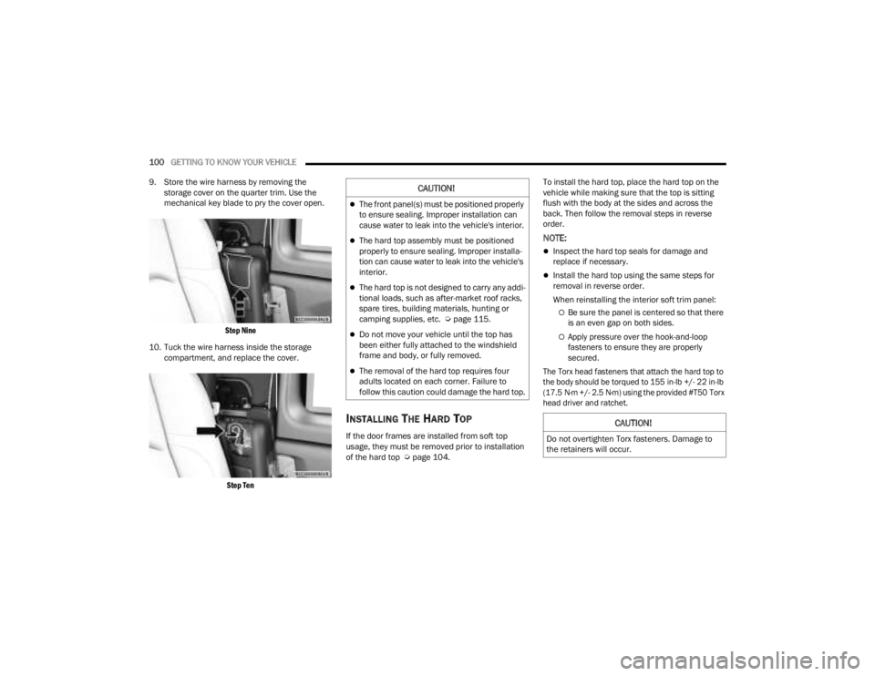
9. Store the wire harness by removing the storage cover on the quarter trim. Use the
mechanical key blade to pry the cover open.
Step Nine
10. Tuck the wire harness inside the storage compartment, and replace the cover.
Step Ten
INSTALLING THE HARD TOP
If the door frames are installed from soft top
usage, they must be removed prior to installation
of the hard top Ú page 104. To install the hard top, place the hard top on the
vehicle while making sure that the top is sitting
flush with the body at the sides and across the
back. Then follow the removal steps in reverse
order.
NOTE:
Inspect the hard top seals for damage and
replace if necessary.
Install the hard top using the same steps for
removal in reverse order.
When reinstalling the interior soft trim panel:
Be sure the panel is centered so that there
is an even gap on both sides.
Apply pressure over the hook-and-loop
fasteners to ensure they are properly
secured.
The Torx head fasteners that attach the hard top to
the body should be torqued to 155 in-lb +/- 22 in-lb
(17.5 N·m +/- 2.5 N·m) using the provided #T50 Torx
head driver and ratchet.
CAUTION!
The front panel(s) must be positioned properly
to ensure sealing. Improper installation can
cause water to leak into the vehicle's interior.
The hard top assembly must be positioned
properly to ensure sealing. Improper installa -
tion can cause water to leak into the vehicle's
interior.
The hard top is not designed to carry any addi -
tional loads, such as after-market roof racks,
spare tires, building materials, hunting or
camping supplies, etc. Ú page 115.
Do not move your vehicle until the top has
been either fully attached to the windshield
frame and body, or fully removed.
The removal of the hard top requires four
adults located on each corner. Failure to
follow this caution could damage the hard top.
CAUTION!
Do not overtighten Torx fasteners. Damage to
the retainers will occur.
23_JT_OM_EN_USC_t.book Page 100
Page 146 of 448
144
STARTING AND OPERATING
STARTING THE ENGINE — GASOLINE
ENGINE (IF EQUIPPED)
Before starting your vehicle, adjust your seat,
adjust both inside and outside mirrors, and fasten
your seat belts.
MANUAL TRANSMISSION — IF EQUIPPED
Apply the parking brake, place the gear selector in
NEUTRAL, and press the clutch pedal before
starting the vehicle. This vehicle is equipped with a
clutch interlocking ignition system. It will not start
unless the clutch pedal is pressed to the floor.
Four-Wheel Drive Models Only
In 4L mode, if the vehicle is stalled, the engine will
start regardless of whether or not the clutch pedal
is pressed to the floor. This feature enhances
off-road performance by allowing the vehicle to
start when in 4L without having to press the clutch
pedal. The 4WD LOW Indicator Light will illuminate
when the transfer case has been shifted into this
mode.
AUTOMATIC TRANSMISSION —
I
F EQUIPPED
Start the vehicle with the gear selector in the PARK
position (vehicle can also be started in NEUTRAL).
Apply the brake before shifting to any driving
range.
NORMAL STARTING
To Turn On The Engine Using The ENGINE START/
STOP Button
1. The transmission must be in PARK or NEUTRAL.
2. Press and hold the brake pedal while pushing
the ENGINE START/STOP button once.
3. The system starts the vehicle. If the vehicle fails to start, the starter will disengage
automatically after 10 seconds.
4. If you wish to stop the cranking of the engine prior to the engine starting, push the ENGINE
START/STOP button again.
To Turn Off The Engine Using The ENGINE START/
STOP Button
1. Place the gear selector in PARK, then push and release the ENGINE START/STOP button.
The ignition will return to the OFF position.
2. If the gear selector is not in PARK (with vehicle stopped) and the ENGINE START/STOP button
is pushed once, the transmission will automat -
ically select PARK and the engine will turn off,
WARNING!
When exiting the vehicle, always remove the
key fob from the ignition and lock your vehicle.
Never leave children alone in a vehicle, or with
access to an unlocked vehicle.
Allowing children to be in a vehicle unattended
is dangerous for a number of reasons. A child
or others could be seriously or fatally injured.
Children should be warned not to touch the
parking brake, brake pedal or the gear
selector.
Do not leave the key fob in or near the vehicle,
or in a location accessible to children. A child
could operate power windows, other controls,
or move the vehicle.
Do not leave children or animals inside parked
vehicles in hot weather. Interior heat build-up
may cause serious injury or death.
23_JT_OM_EN_USC_t.book Page 144
Page 148 of 448
146STARTING AND OPERATING
Vehicle is not in PARK
Vehicle speed is 1.2 mph (1.9 km/h) or less
Ignition is switched from ON/RUN to OFF
NOTE:For Keyless Enter ‘n Go™ equipped vehicles, the
engine will turn off and the ignition will change to
ACC position. After 30 minutes the ignition
switches to OFF automatically, unless the driver
turns the ignition OFF.
If the vehicle is not in PARK and the driver exits the
vehicle with the engine running, the vehicle may
AutoPark.
AutoPark will engage when all of these conditions
are met:
Vehicle is equipped with an 8-speed transmis -
sion
Driver door is ajar or if the driver door is
removed and the driver is not on the seat (seat
pad sensor detects driver missing)
Vehicle is not in PARK
Vehicle speed is 1.2 mph (1.9 km/h) or less
Driver seat belt is unbuckled
Brake pedal is not pressed
The message “ AutoPark Engaged Shift To P Then
Shift To Gear ” will display in the instrument cluster.
NOTE:In some cases the ParkSense graphic will be
displayed in the instrument cluster. In these cases,
the gear selector must be returned to “P” to select
desired gear.
If the driver shifts into PARK while moving, the
vehicle may AutoPark.
AutoPark will engage ONLY when vehicle speed is
1.2 mph (1.9 km/h) or less.
The message “ Vehicle Speed Is Too High To Shift
To P ” will be displayed in the instrument cluster if
vehicle speed is above 1.2 mph (1.9 km/h).
4WD LOW
AutoPark will be disabled when operating the
vehicle in 4WD LOW.
The message “ AutoPark Disabled ” will be
displayed in the instrument cluster. Additional customer warnings will be given when
both of these conditions are met:
Vehicle is not in PARK
Driver’s door is ajar
The message “ AutoPark Not Engaged” will be
displayed in the instrument cluster. A warning
chime will continue until you shift the vehicle into
PARK or the driver’s door is closed.
ALWAYS DO A VISUAL CHECK
that your vehicle is in
PARK by looking for the “P” in the instrument
cluster display and on the gear selector. As an
added precaution, always apply the parking brake
when exiting the vehicle.
EXTREME COLD WEATHER
(B
ELOW –22°F OR −30°C)
To ensure reliable starting at these temperatures,
use of an externally powered electric engine block
heater (available from an authorized dealer) is
recommended.
EXTENDED PARK STARTING
NOTE:Extended Park condition occurs when the vehicle
has not been started or driven for at least 30 days.
1. Install a battery charger or jumper cables to
the battery to ensure a full battery charge
during the crank cycle.
WARNING!
If vehicle speed is above 1.2 mph (1.9 km/h), the
transmission will default to NEUTRAL until the
vehicle speed drops below 1.2 mph (1.9 km/h). A
vehicle left in the NEUTRAL position can roll. As
an added precaution, always apply the parking
brake when exiting the vehicle.
23_JT_OM_EN_USC_t.book Page 146
Page 149 of 448
STARTING AND OPERATING147
(Continued)
2. Press and hold the brake pedal while pushing
the ENGINE START/STOP button once.
3. If the engine fails to start within 10 seconds, place the ignition in the OFF position, wait
10 to 15 seconds to allow the starter to cool,
then repeat the “Extended Park Starting”
procedure.
4. If the engine fails to start after eight attempts, allow the starter to cool for at least
10 minutes, then repeat the procedure.
IF ENGINE FAILS TO START
If the engine fails to start after you have followed
the “Normal Starting” procedure and the vehicle
has not experienced an extended park condition
as defined previously, it may be flooded. Push the
accelerator pedal all the way to the floor and hold
it there. Crank the engine for no more than 10
seconds. This should clear any excess fuel in case
the engine is flooded. Leave the ignition key in the
ON/ RUN position, release the accelerator pedal
and repeat the “Normal Starting” procedure.
AFTER STARTING
The idle speed is controlled automatically and will
decrease as the engine warms up.
STARTING THE ENGINE — DIESEL ENGINE
(IF EQUIPPED)
Before starting your vehicle, adjust your seat, both
inside and outside mirrors, and fasten your seat
belts.
The starter is allowed to crank for up to 25-second
intervals. Waiting two minutes between such
intervals will protect the starter from overheating.
CAUTION!
To prevent damage to the starter, do not crank
continuously for more than 10 seconds at a
time. Wait 10 to 15 seconds before trying again.
WARNING!
Never pour fuel or other flammable liquid into
the throttle body air inlet opening in an
attempt to start the vehicle. This could result
in flash fire causing serious personal injury.
Do not attempt to push or tow your vehicle to
get it started. Vehicles equipped with an auto -
matic transmission cannot be started this
way. Unburned fuel could enter the catalytic
converter and once the engine has started,
ignite and damage the converter and vehicle.
If the vehicle has a discharged battery,
booster cables may be used to obtain a start
from a booster battery or the battery in
another vehicle. This type of start can be
dangerous if done improperly Ú page 343.
CAUTION!
To prevent damage to the starter, do not
continuously crank the engine for more than
10 seconds at a time. Wait 10 to 15 seconds
before trying again.
WARNING!
Before exiting a vehicle, always come to a
complete stop, then shift the automatic trans -
mission into PARK and apply the parking
brake.
Always make sure the keyless ignition node is
in the OFF position, key fob is removed from
the vehicle and vehicle is locked.
Never leave children alone in a vehicle, or with
access to an unlocked vehicle. Leaving chil -
dren in a vehicle unattended is dangerous for
a number of reasons. A child or others could
be seriously or fatally injured. Children should
be warned not to touch the parking brake,
brake pedal or the gear selector.
4
23_JT_OM_EN_USC_t.book Page 147
Page 150 of 448
148STARTING AND OPERATING
NOTE:Engine start-up in very low ambient temperature
could result in evident white smoke. This condition
will disappear as the engine warms up.
AUTOMATIC TRANSMISSION
Start the engine with the transmission gear
selector in the PARK (P) position. Apply the brake
before shifting to any driving range.
EXTREME COLD WEATHER
The cartridge block heater clips into the engine
block near the water jacket and transfers heat to
the coolant. It requires a 110–115 Volt AC
electrical outlet with a grounded, three-wire
extension cord. Its use is recommended for
environments that routinely fall below -10°F
(-23°C). It should be used when the vehicle has not
been running overnight or longer periods and
should be plugged in two hours prior to start. Its
use is required for cold starts with temperatures
under -20°F (-28°C).
NOTE:The engine block heater and heater cord are
factory installed options. If your vehicle is not
equipped, engine block heaters and heater cords
are available from an authorized Mopar® dealer.
A 12 Volt heater built into the fuel filter housing
aids in preventing fuel gelling. It is controlled by
a built-in thermostat.
A Diesel Pre-Heat system both improves engine
starting and reduces the amount of white
smoke generated by a warming engine.
NORMAL STARTING
Observe the instrument cluster lights when
starting the engine.
NOTE:Normal starting of either a cold or a warm engine is
obtained without pumping or pressing the accel -
erator pedal.
1. Always apply the parking brake.
2. Press and hold the brake pedal while pushing the ENGINE START/STOP button once.
NOTE:A delay of the start of up to five seconds is possible
under very cold conditions. The “Wait to Start”
telltale will be illuminated during the preheat
process. When the engine “Wait To Start” telltale
turns off the engine will automatically crank.
Do not leave the key fob in or near the vehicle,
or in a location accessible to children, and do
not leave the ignition of a vehicle equipped
with Keyless Enter ‘n Go™ in the ACC or ON/
RUN position. A child could operate power
windows, other controls, or move the vehicle.
Do not leave children or animals inside parked
vehicles in hot weather. Interior heat build-up
may cause serious injury or death.
CAUTION!
The engine is allowed to crank as long as
25 seconds. If the engine fails to start during
this period, please wait at least two minutes
for the starter to cool before repeating start
procedure.
If the Water in Fuel Indicator Light remains on,
DO NOT START engine before you drain the
water from the fuel filters to avoid engine
damage Ú page 368.
WARNING!
CAUTION!
If the Water in Fuel Indicator Light remains on,
DO NOT START the engine before you drain the
water from the fuel filters to avoid engine
damage Úpage 368.
23_JT_OM_EN_USC_t.book Page 148