fuel cap JEEP GLADIATOR 2023 Owners Manual
[x] Cancel search | Manufacturer: JEEP, Model Year: 2023, Model line: GLADIATOR, Model: JEEP GLADIATOR 2023Pages: 448, PDF Size: 17.37 MB
Page 7 of 448
5
STOP/START SYSTEM — AUTOMATIC
TRANSMISSION (IF EQUIPPED) ........................ 169 Autostop Mode .............................................. 169Possible Reasons The Engine Does Not
Autostop ......................................................... 170
To Start The Engine While In Autostop
Mode .............................................................. 170
To Manually Turn Off The Stop/Start
System ........................................................... 171To Manually Turn On The Stop/Start
System ........................................................... 171System Malfunction ...................................... 171
STOP/START SYSTEM — MANUAL
TRANSMISSION (IF EQUIPPED) .........................171
Autostop Mode .............................................. 172Possible Reasons The Engine Does Not
Autostop ......................................................... 172
To Start The Engine While In Autostop
Mode .............................................................. 172
To Manually Turn Off The Stop/Start
System ........................................................... 173To Manually Turn On The Stop/Start
System ........................................................... 173System Malfunction ...................................... 173
CRUISE CONTROL SYSTEMS —
IF EQUIPPED ........................................................ 173
Cruise Control ............................................... 173
Adaptive Cruise Control (ACC) ...................... 175 PARKSENSE FRONT/REAR PARK ASSIST
SYSTEM — IF EQUIPPED .................................... 184
ParkSense Sensors ....................................... 184
ParkSense Warning Display ......................... 184
ParkSense Display ........................................ 184Enabling And Disabling ParkSense .............. 187Service The ParkSense Park Assist
System ........................................................... 187
Cleaning The ParkSense System ................. 187
ParkSense System Usage Precautions........ 188
PARKVIEW REAR BACK UP CAMERA............... 189
TRAILCAM SYSTEM — IF EQUIPPED ................ 190
REFUELING THE VEHICLE — GASOLINE
ENGINE (IF EQUIPPED) ....................................... 191 Fuel Filler Cap................................................ 191Loose Fuel Filler Cap Message ................... 192
REFUELING THE VEHICLE — DIESEL ENGINE
(IF EQUIPPED) ..................................................... 192
Avoid Using Contaminated Fuel ................... 193Bulk Fuel Storage — Diesel Fuel................... 193Diesel Exhaust Fluid ..................................... 193
VEHICLE LOADING .............................................. 195
Certification Label ......................................... 195
TRAILER TOWING ............................................... 197
Common Towing Definitions......................... 197
Trailer Hitch Classification ............................ 199
Trailer Towing Weights (Maximum Trailer
Weight Ratings) ............................................ 199
Trailer And Tongue Weight............................ 202
Towing Requirements ................................... 202Towing Tips .................................................... 204 RECREATIONAL TOWING (BEHIND
MOTORHOME) ...................................................... 205
Towing This Vehicle Behind Another
Vehicle ........................................................... 205
Recreational Towing — Four-Wheel Drive
Models ........................................................... 205
DRIVING TIPS ....................................................... 207
On-Road Driving Tips..................................... 207Off-Road Driving Tips .................................... 207
MULTIMEDIA
UCONNECT SYSTEMS ......................................... 214
CYBERSECURITY ................................................. 214
UCONNECT SETTINGS ......................................... 215 Customer Programmable Features ............. 215
UCONNECT INTRODUCTION................................ 230
System Overview .......................................... 230Drag & Drop Menu Bar ................................. 232
Safety And General Information................... 232
UCONNECT MODES ............................................. 233
Steering Wheel Audio Controls .................... 233
Radio Mode .................................................. 234Media Mode ................................................. 242
Phone Mode ................................................. 244
ANDROID AUTO™ & APPLE CARPLAY® —
IF EQUIPPED ......................................................... 254
Android Auto™
S
........................................ 254
Apple CarPlay®
S
....................................... 256
Android Auto™ And Apple CarPlay® Tips
And Tricks ...................................................... 258
23_JT_OM_EN_USC_t.book Page 5
Page 10 of 448
8
TECHNICAL SPECIFICATIONS
VEHICLE IDENTIFICATION NUMBER (VIN)......... 418
BRAKE SYSTEM .................................................. 418
WHEEL AND TIRE TORQUE SPECIFICATIONS .. 418Torque Specifications ................................... 418
FUEL REQUIREMENTS — GASOLINE ENGINE ... 419
3.6L Engine.................................................... 419
Reformulated Gasoline ................................. 419Materials Added To Fuel ............................... 419
Gasoline/Oxygenate Blends ......................... 420Do Not Use E-85 In Non-Flex Fuel
Vehicles .......................................................... 420
CNG And LP Fuel System Modifications ...... 420
Methylcyclopentadienyl Manganese
Tricarbonyl (MMT) In Gasoline...................... 420Fuel System Cautions ................................... 420
FUEL REQUIREMENTS – DIESEL ENGINE ........ 421
Diesel Fuel Specifications ............................ 421
Biodiesel Fuel Requirements ....................... 422
FLUID CAPACITIES .............................................. 423
ENGINE FLUIDS AND LUBRICANTS ................... 424 CHASSIS FLUIDS AND LUBRICANTS .................42
7
CUSTOMER ASSISTANCE
SUGGESTIONS FOR OBTAINING SERVICE FOR
YOUR VEHICLE .................................................... 428
Prepare For The Appointment ...................... 428Prepare A List ................................................ 428Be Reasonable With Requests..................... 428
IF YOU NEED ASSISTANCE ................................ 428
Roadside Assistance..................................... 428
FCA US LLC Customer Center....................... 430
FCA Canada Inc. Customer Center............... 430
Mexico ............................................................ 430
Puerto Rico And U.S. Virgin Islands.............. 430Customer Assistance For The Hearing Or
Speech Impaired (TDD/TTY) ......................... 430
Service Contract ........................................... 430 WARRANTY INFORMATION ................................ 431
MOPAR® PARTS ................................................. 431
REPORTING SAFETY DEFECTS .......................... 431
In The 50 United States And
Washington, D.C............................................ 431
In Canada ...................................................... 431
PUBLICATION ORDER FORMS .......................... 431
CHANGE OF OWNERSHIP OR ADDRESS .......... 432
GENERAL INFORMATION.................................... 432
23_JT_OM_EN_USC_t.book Page 8
Page 14 of 448
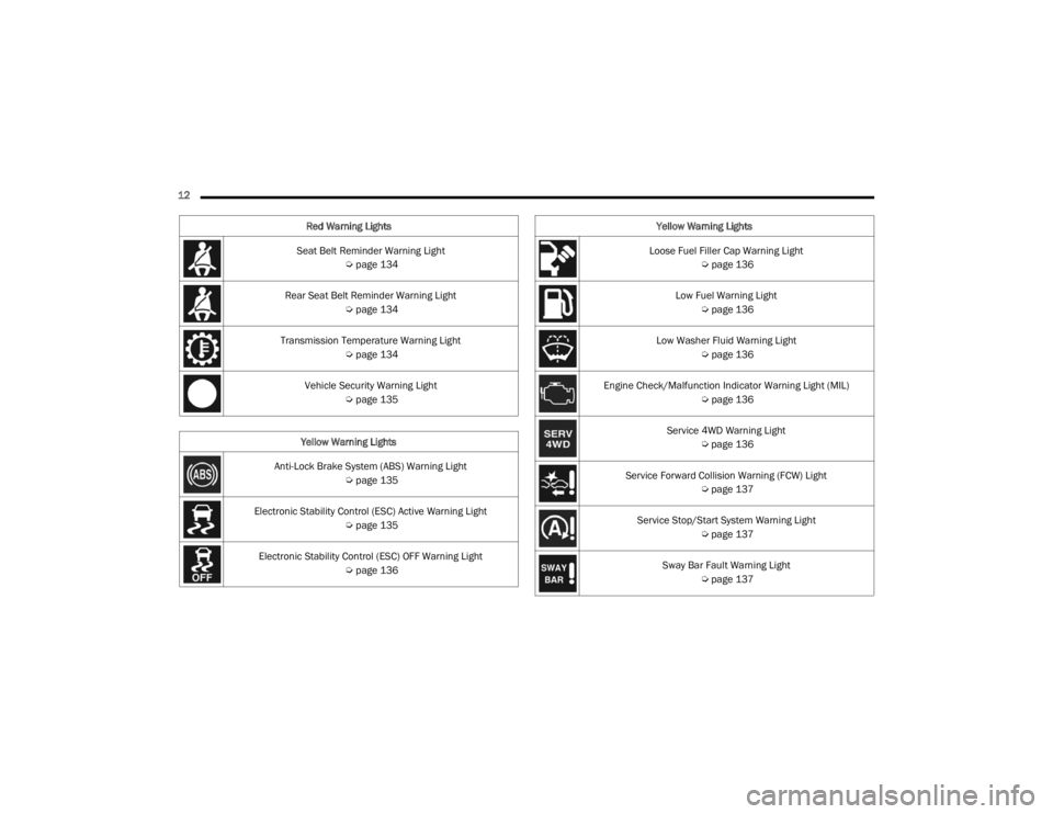
12 Seat Belt Reminder Warning Light Úpage 134
Rear Seat Belt Reminder Warning Light Úpage 134
Transmission Temperature Warning Light Úpage 134
Vehicle Security Warning Light Úpage 135
Yellow Warning Lights
Anti-Lock Brake System (ABS) Warning Light Úpage 135
Electronic Stability Control (ESC) Active Warning Light Úpage 135
Electronic Stability Control (ESC) OFF Warning Light Úpage 136
Red Warning Lights
Loose Fuel Filler Cap Warning Light
Úpage 136
Low Fuel Warning Light Úpage 136
Low Washer Fluid Warning Light Úpage 136
Engine Check/Malfunction Indicator Warning Light (MIL) Úpage 136
Service 4WD Warning Light Úpage 136
Service Forward Collision Warning (FCW) Light Úpage 137
Service Stop/Start System Warning Light Úpage 137
Sway Bar Fault Warning Light Úpage 137
Yellow Warning Lights
23_JT_OM_EN_USC_t.book Page 12
Page 138 of 448
136GETTING TO KNOW YOUR INSTRUMENT PANEL
Electronic Stability Control (ESC) OFF
Warning Light — If Equipped
This warning light indicates the Electronic
Stability Control (ESC) is off.
Each time the ignition is turned to ON/RUN or ACC/
ON/RUN, the ESC system will be on, even if it was
turned off previously.
Loose Fuel Filler Cap Warning Light —
If Equipped
This warning light will illuminate when the
fuel filler cap is loose. Properly close the
filler cap to disengage the light. If the
light does not turn off, please see an
authorized dealer.
Low Fuel Warning Light
When the fuel level reaches
approximately 2.0 gal (7.5 L), this light
will turn on and a chime will sound. The
light will remain on until fuel is added.
Low Washer Fluid Warning Light —
If Equipped
This warning light will illuminate when the
windshield washer fluid is low
Ú page 364.
Engine Check/Malfunction Indicator
Warning Light (MIL)
The Engine Check/Malfunction Indicator
Light (MIL) is a part of an Onboard
Diagnostic System called OBD II that
monitors engine and automatic
transmission control systems. This warning light
will illuminate when the ignition is in the ON/RUN
position before engine start. If the bulb does not
come on when turning the ignition switch from OFF
to ON/RUN, have the condition checked promptly.
Certain conditions, such as a loose or missing gas
cap, poor quality fuel, etc., may illuminate the light
after engine start. The vehicle should be serviced if
the light stays on through several typical driving
styles. In most situations, the vehicle will drive
normally and will not require towing.
When the engine is running, the MIL may flash to
alert serious conditions that could lead to
immediate loss of power or severe catalytic
converter damage. The vehicle should be serviced
by an authorized dealer as soon as possible if this
occurs.
Service 4WD Warning Light — If Equipped
This warning light will illuminate to signal
a fault with the 4WD system. If the light
stays on or comes on during driving, it
means that the 4WD system is not
functioning properly and that service is required. It
is recommend you drive to the nearest service
center and have the vehicle serviced immediately.
WARNING!
A malfunctioning catalytic converter, as
previously referenced, can reach higher
temperatures than in normal operating
conditions. This can cause a fire if you drive
slowly or park over flammable substances such
as dry plants, wood, cardboard, etc. This could
result in death or serious injury to the driver,
occupants or others.
CAUTION!
Prolonged driving with the Malfunction Indicator
Light (MIL) on could cause damage to the
vehicle control system. It also could affect fuel
economy and driveability. If the MIL is flashing,
severe catalytic converter damage and power
loss will soon occur. Immediate service is
required.
23_JT_OM_EN_USC_t.book Page 136
Page 193 of 448
STARTING AND OPERATING191
The TrailCam view can also be activated by
pressing the icon on the Back Up Camera view.
The Back Up Camera view can also be activated by
pressing the icon on the TrailCam view.
When the vehicle is shifted out of REVERSE with
Camera Delay turned off and TrailCam view is
active, the TrailCam mode is exited and the
previous screen appears again.
When the vehicle is shifted out of REVERSE with
Camera Delay turned on and the TrailCam view is
active, the TrailCam image will be displayed for up
to 10 seconds unless the vehicle speed exceeds
8 mph (13 km/h), the transmission is shifted into
PARK, the ignition is placed in the OFF position, or
the touchscreen X button to disable display of the
TrailCam view is pressed.
Whenever the TrailCam image is activated through
the Manual Activation Methods, and the vehicle
speed is greater than or equal to 8 mph (13 km/h),
a display timer for the image is initiated. The image
will continue to be displayed until the display timer
exceeds 10 seconds.
NOTE:
If the vehicle speed remains below 8 mph
(13 km/h) while in 2WD or 4WD High, the
TrailCam image will be displayed continuously
until deactivated via the touchscreen X button,
the transmission is shifted into PARK, or the
ignition is placed in the OFF position.
The touchscreen X button to disable the display
of the camera image is made available ONLY
when the vehicle is not in REVERSE.
The TrailCam view will stay active regardless of
the vehicle speed and time while in 4WD Low.
Cleaning The TrailCam
Press and hold the Clean Camera button located
on the TrailCam view to wash the TrailCam. Washer
fluid will stop when the button is released.
The camera can be washed up to 20 seconds at
a time while holding the button.
The Clean Camera system is not available when
windshield washing is in process.
When enabled, active dynamic Tire Lines are
projected on the ground plane of the TrailCam view
based on the steering wheel position.
REFUELING THE VEHICLE — GASOLINE
ENGINE (IF EQUIPPED)
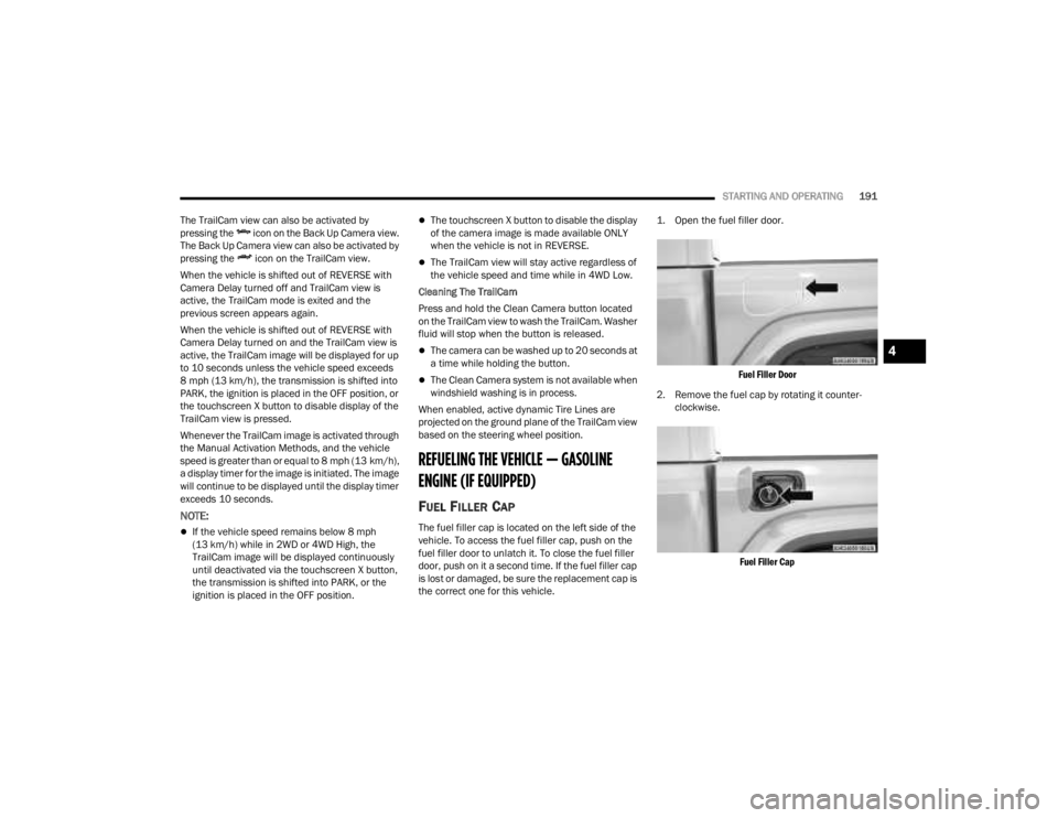
FUEL FILLER CAP
The fuel filler cap is located on the left side of the
vehicle. To access the fuel filler cap, push on the
fuel filler door to unlatch it. To close the fuel filler
door, push on it a second time. If the fuel filler cap
is lost or damaged, be sure the replacement cap is
the correct one for this vehicle.
1. Open the fuel filler door.
Fuel Filler Door
2. Remove the fuel cap by rotating it counter -
clockwise.
Fuel Filler Cap
4
23_JT_OM_EN_USC_t.book Page 191
Page 194 of 448
192STARTING AND OPERATING
3. Fully insert the gasoline nozzle into the filler pipe. Fill the vehicle with fuel.
4. When the fuel nozzle “clicks” or shuts off, the fuel tank is full. Wait five seconds before
removing the fuel nozzle to allow excess fuel to
drain from nozzle.
5. Remove gasoline nozzle, reinstall fuel cap and close the fuel filler door.
NOTE:
When the fuel nozzle “clicks” or shuts off, the
fuel tank is full.
Tighten the fuel filler cap about a quarter turn
until you hear one click. This is an indication that
the cap is properly tightened.
If the fuel filler cap is not tightened properly, the
MIL will come on. Be sure the cap is tightened
every time the vehicle is refueled.
LOOSE FUEL FILLER CAP MESSAGE
After fuel has been added, the vehicle diagnostic
system can determine if the fuel filler cap is
possibly loose, improperly installed, or damaged. If
the system detects a malfunction, the “gASCAP”
message will display in the odometer display.
Tighten the gas cap until a "clicking" sound is heard. This is an indication that the gas cap is
properly tightened. Push the odometer reset
button to turn the message off. If the problem
persists, the message will appear the next time the
vehicle is started. This might indicate a damaged
cap. If the problem is detected twice in a row, the
system will turn on the MIL. Resolving the problem
will turn the MIL off.
REFUELING THE VEHICLE — DIESEL ENGINE
(IF EQUIPPED)
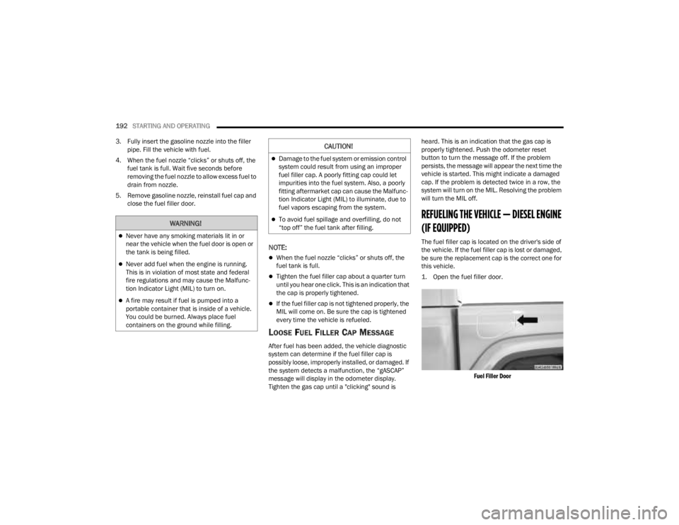
The fuel filler cap is located on the driver's side of
the vehicle. If the fuel filler cap is lost or damaged,
be sure the replacement cap is the correct one for
this vehicle.
1. Open the fuel filler door.
Fuel Filler Door
WARNING!
Never have any smoking materials lit in or
near the vehicle when the fuel door is open or
the tank is being filled.
Never add fuel when the engine is running.
This is in violation of most state and federal
fire regulations and may cause the Malfunc -
tion Indicator Light (MIL) to turn on.
A fire may result if fuel is pumped into a
portable container that is inside of a vehicle.
You could be burned. Always place fuel
containers on the ground while filling.
CAUTION!
Damage to the fuel system or emission control
system could result from using an improper
fuel filler cap. A poorly fitting cap could let
impurities into the fuel system. Also, a poorly
fitting aftermarket cap can cause the Malfunc -
tion Indicator Light (MIL) to illuminate, due to
fuel vapors escaping from the system.
To avoid fuel spillage and overfilling, do not
“top off” the fuel tank after filling.
23_JT_OM_EN_USC_t.book Page 192
Page 195 of 448
STARTING AND OPERATING193
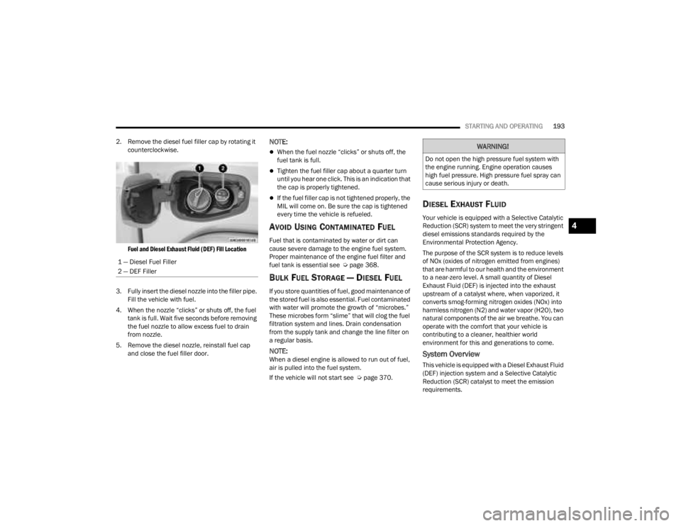
2. Remove the diesel fuel filler cap by rotating it counterclockwise.
Fuel and Diesel Exhaust Fluid (DEF) Fill Location
3. Fully insert the diesel nozzle into the filler pipe. Fill the vehicle with fuel.
4. When the nozzle “clicks” or shuts off, the fuel tank is full. Wait five seconds before removing
the fuel nozzle to allow excess fuel to drain
from nozzle.
5. Remove the diesel nozzle, reinstall fuel cap and close the fuel filler door.
NOTE:
When the fuel nozzle “clicks” or shuts off, the
fuel tank is full.
Tighten the fuel filler cap about a quarter turn
until you hear one click. This is an indication that
the cap is properly tightened.
If the fuel filler cap is not tightened properly, the
MIL will come on. Be sure the cap is tightened
every time the vehicle is refueled.
AVOID USING CONTAMINATED FUEL
Fuel that is contaminated by water or dirt can
cause severe damage to the engine fuel system.
Proper maintenance of the engine fuel filter and
fuel tank is essential see Ú page 368.
BULK FUEL STORAGE — DIESEL FUEL
If you store quantities of fuel, good maintenance of
the stored fuel is also essential. Fuel contaminated
with water will promote the growth of “microbes.”
These microbes form “slime” that will clog the fuel
filtration system and lines. Drain condensation
from the supply tank and change the line filter on
a regular basis.
NOTE:When a diesel engine is allowed to run out of fuel,
air is pulled into the fuel system.
If the vehicle will not start see Ú page 370.
DIESEL EXHAUST FLUID
Your vehicle is equipped with a Selective Catalytic
Reduction (SCR) system to meet the very stringent
diesel emissions standards required by the
Environmental Protection Agency.
The purpose of the SCR system is to reduce levels
of NOx (oxides of nitrogen emitted from engines)
that are harmful to our health and the environment
to a near-zero level. A small quantity of Diesel
Exhaust Fluid (DEF) is injected into the exhaust
upstream of a catalyst where, when vaporized, it
converts smog-forming nitrogen oxides (NOx) into
harmless nitrogen (N2) and water vapor (H2O), two
natural components of the air we breathe. You can
operate with the comfort that your vehicle is
contributing to a cleaner, healthier world
environment for this and generations to come.
System Overview
This vehicle is equipped with a Diesel Exhaust Fluid
(DEF) injection system and a Selective Catalytic
Reduction (SCR) catalyst to meet the emission
requirements.
1 — Diesel Fuel Filler
2 — DEF Filler
WARNING!
Do not open the high pressure fuel system with
the engine running. Engine operation causes
high fuel pressure. High pressure fuel spray can
cause serious injury or death.
4
23_JT_OM_EN_USC_t.book Page 193
Page 196 of 448
194STARTING AND OPERATING
The DEF injection system consists of the following
components:
DEF tank
DEF pump
DEF injector
Electronically-heated DEF Lines
NOx sensors
Temperature sensors
SCR catalyst
The DEF injection system and SCR catalyst enable
the achievement of diesel emissions
requirements; while maintaining outstanding fuel
economy, drivability, torque and power ratings.
For system messages and warnings see
Ú page 121.
NOTE:
Your vehicle is equipped with a DEF injection
system. You may occasionally hear an audible
clicking noise from under the vehicle at a stop.
This is normal operation.
The DEF pump will run for a period of time after
engine shutdown to purge the DEF system. This
is normal operation and may be audible from
the rear of the vehicle.
Diesel Exhaust Fluid Storage
Diesel Exhaust Fluid (DEF) is considered a very
stable product with a long shelf life. If DEF is kept
in temperatures between 10° and 90°F (-12° and
32°C), it will last a minimum of one year.
DEF is subject to freezing at the lowest
temperatures. For example, DEF may freeze at
temperatures at or below 12°F (-11°C). The
system has been designed to operate in this
environment.
NOTE:When working with DEF, it is important to know
that:
Any containers or parts that come into contact
with DEF must be DEF compatible (plastic or
stainless steel). Copper, brass, aluminum, iron
or non-stainless steel should be avoided as they
are subject to corrosion by DEF.
If DEF is spilled, it should be wiped up
completely.
Adding Diesel Exhaust Fluid
The DEF gauge (located on the instrument cluster
display) will display the level of DEF remaining in
the tank Ú page 121.
NOTE:Driving conditions (altitude, vehicle speed, load,
etc.) will affect the amount of DEF that is used in
your vehicle.
DEF FILL PROCEDURE
NOTE:
For the correct DEF fluid type see Ú page 424.
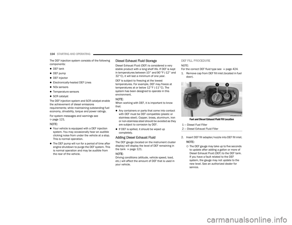
1. Remove cap from DEF fill inlet (located in fuel door).
Fuel and Diesel Exhaust Fluid Fill Location
2. Insert DEF fill adapter/nozzle into DEF fill inlet.
NOTE:
The DEF gauge may take up to five seconds
to update after adding a gallon or more of
Diesel Exhaust Fluid (DEF) to the DEF tank.
If you have a fault related to the DEF
system, the gauge may not update to the
new level. See an authorized dealer for
service.
1 — Diesel Fuel Filler
2 — Diesel Exhaust Fluid Filler
23_JT_OM_EN_USC_t.book Page 194
Page 197 of 448
STARTING AND OPERATING195
(Continued)
The DEF gauge may also not immediately
update after a refill if the temperature of the
DEF fluid is below 12°F (-11°C). The DEF
line heater will possibly warm up the DEF
fluid and allow the gauge to update after a
period of run time. Under very cold condi -
tions, it is possible that the gauge may not
reflect the new fill level for several drives.
Excessive overfilling of the DEF tank can
result in a MIL lamp/fault code and inaccu-
rate level readings.
Refilling With Nozzles
You can fill up at any DEF distributor.
Proceed as follows:
Insert the DEF nozzle in the filler, start
refilling and stop refilling at the first shut-off
(the shut-off indicates that the DEF tank is
full). Do not proceed with the refilling, to
prevent spillage of DEF.
Extract the nozzle.
Refilling With Containers
Proceed as follows:
Check the expiration date.
Read the advice for use on the label before
pouring the content of the bottle into the
DEF tank.
If systems which cannot be screwed in
(e.g. tanks) are used for refilling, after the
indication appears on the instrument panel
display Úpage 121 fill the DEF tank with no
more than 2 gal (8 L).
If containers which can be screwed to the
filler are used, the reservoir is full when the
DEF level in the container stops pouring out.
Do not proceed further.
3. Stop filling the DEF tank immediately when any of the following happen: DEF stops flowing
from the fill bottle into the DEF fill inlet, DEF
splashes out the fill inlet, or a DEF pump
nozzle automatically shuts off.
4. Reinstall cap onto DEF fill inlet.
VEHICLE LOADING
CERTIFICATION LABEL
As required by National Highway Traffic Safety
Administration regulations, your vehicle has a
certification label affixed to the driver's side door or
pillar.
CAUTION!
To avoid DEF spillage, and possible damage to
the DEF tank from overfilling, do not “top off”
the DEF tank after filling.
DO NOT OVERFILL. DEF will freeze below 12ºF
(-11ºC). The DEF system is designed to work in
temperatures below the DEF freezing point,
however, if the tank is overfilled and freezes,
the system could be damaged.
When DEF is spilled, clean the area immedi -
ately with water and use an absorbent mate -
rial to soak up the spills on the ground.
Do not attempt to start your engine if DEF is
accidentally added to the diesel fuel tank as it
can result in severe damage to your engine,
including but not limited to failure of the fuel
pump and injectors.
Never add anything other than DEF to the tank
– especially any form of hydrocarbon such as
diesel fuel, fuel system additives, gasoline, or
any other petroleum-based product. Even a
very small amount of these, less than
100 parts per million or less than 1 oz. per
78 gal (295 L) will contaminate the entire DEF
system and will require replacement. If
owners use a container, funnel or nozzle when
refilling the tank, it should either be new or
one that is has only been used for adding DEF.
Mopar® provides an attachable nozzle with its
DEF for this purpose.
CAUTION!
4
23_JT_OM_EN_USC_t.book Page 195
Page 198 of 448
196STARTING AND OPERATING
This label contains the month and year of
manufacture, Gross Vehicle Weight Rating
(GVWR), front and rear Gross Axle Weight Rating
(GAWR), and Vehicle Identification Number (VIN). A
Month-Day-Hour (MDH) number is included on this
label and indicates the Month, Day and Hour of
manufacture. The bar code that appears on the
bottom of the label is your VIN.
Gross Vehicle Weight Rating (GVWR)
The GVWR is the total permissible weight of your
vehicle including driver, passengers, vehicle,
options and cargo. The label also specifies
maximum capacities of front and rear Gross Axle
Weight Rating (GAWR). Total load must be limited
so GVWR on front and rear GAWR are not
exceeded.
Payload
The payload of a vehicle is defined as the allowable
load weight a truck can carry, including the weight
of the driver, all passengers, options and cargo.
Gross Axle Weight Rating (GAWR)
The GAWR is the maximum permissible load on the
front and rear axles. The load must be distributed
in the cargo area so that the GAWR of each axle is
not exceeded.
Each axle GAWR is determined by the components
in the system with the lowest load carrying capacity
(axle, springs, tires or wheels). Heavier axles or
suspension components sometimes specified by purchasers for increased durability does not
necessarily increase the vehicle's GVWR.
Tire Size
The tire size on the Vehicle Certification Label
represents the actual tire size on your vehicle.
Replacement tires must be equal to the load
capacity of this tire size.
Rim Size
This is the rim size that is appropriate for the tire
size listed.
Inflation Pressure
This is the cold tire inflation pressure for your
vehicle for all loading conditions up to full GAWR.
Curb Weight
The curb weight of a vehicle is defined as the total
weight of the vehicle with all fluids, including
vehicle fuel, at full capacity conditions, and with no
occupants or cargo loaded into the vehicle. The
front and rear curb weight values are determined
by weighing your vehicle on a commercial scale
before any occupants or cargo are added.
Loading
The actual total weight and the weight of the front
and rear of your vehicle at the ground can best be
determined by weighing it when it is loaded and
ready for operation.
The entire vehicle should first be weighed on a
commercial scale to ensure that the GVWR has not
been exceeded. The weight on the front and rear of
the vehicle should then be determined separately
to be sure that the load is properly distributed over
the front and rear axle. Weighing the vehicle may
show that the GAWR of either the front or rear axles
has been exceeded but the total load is within the
specified GVWR. If so, weight must be shifted from
front to rear or rear to front as appropriate until the
specified weight limitations are met. Store the
heavier items down low and be sure that the
weight is distributed equally. Stow all loose items
securely before driving.
Improper weight distributions can have an adverse
effect on the way your vehicle steers and handles
and the way the brakes operate.
WARNING!
Do not load your vehicle any heavier than the
GVWR or the maximum front and rear GAWR. If
you do, parts on your vehicle can break, or it can
change the way your vehicle handles. This could
cause you to lose control. Overloading can
shorten the life of your vehicle.
23_JT_OM_EN_USC_t.book Page 196