torque specifications JEEP GRAND CHEROKEE 2002 WJ / 2.G Workshop Manual
[x] Cancel search | Manufacturer: JEEP, Model Year: 2002, Model line: GRAND CHEROKEE, Model: JEEP GRAND CHEROKEE 2002 WJ / 2.GPages: 2199, PDF Size: 76.01 MB
Page 5 of 2199
FASTENER USAGE
DESCRIPTION - FASTENER USAGE
WARNING: USE OF AN INCORRECT FASTENER
MAY RESULT IN COMPONENT DAMAGE OR PER-
SONAL INJURY.
Fasteners and torque specifications references in
this Service Manual are identified in metric and SAE
format.
During any maintenance or repair procedures, it is
important to salvage all fasteners (nuts, bolts, etc.)
for reassembly. If the fastener is not salvageable, a
fastener of equivalent specification must be used.
THREADED HOLE REPAIR
DESCRIPTION - THREADED HOLE REPAIR
Most stripped threaded holes can be repaired using
a Helicoilt. Follow the vehicle or Helicoiltrecommen-
dations for application and repair procedures.
INTERNATIONAL SYMBOLS
DESCRIPTION - INTERNATIONAL SYMBOLS
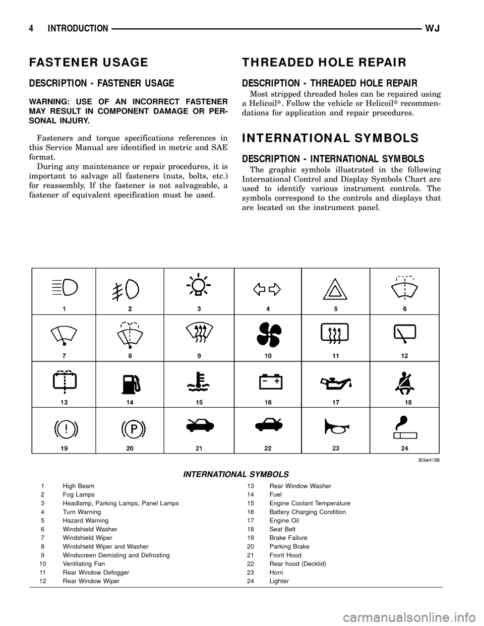
The graphic symbols illustrated in the following
International Control and Display Symbols Chart are
used to identify various instrument controls. The
symbols correspond to the controls and displays that
are located on the instrument panel.
INTERNATIONAL SYMBOLS
1 High Beam 13 Rear Window Washer
2 Fog Lamps 14 Fuel
3 Headlamp, Parking Lamps, Panel Lamps 15 Engine Coolant Temperature
4 Turn Warning 16 Battery Charging Condition
5 Hazard Warning 17 Engine Oil
6 Windshield Washer 18 Seat Belt
7 Windshield Wiper 19 Brake Failure
8 Windshield Wiper and Washer 20 Parking Brake
9 Windscreen Demisting and Defrosting 21 Front Hood
10 Ventilating Fan 22 Rear hood (Decklid)
11 Rear Window Defogger 23 Horn
12 Rear Window Wiper 24 Lighter
4 INTRODUCTIONWJ
Page 8 of 2199
TORQUE REFERENCES
DESCRIPTION
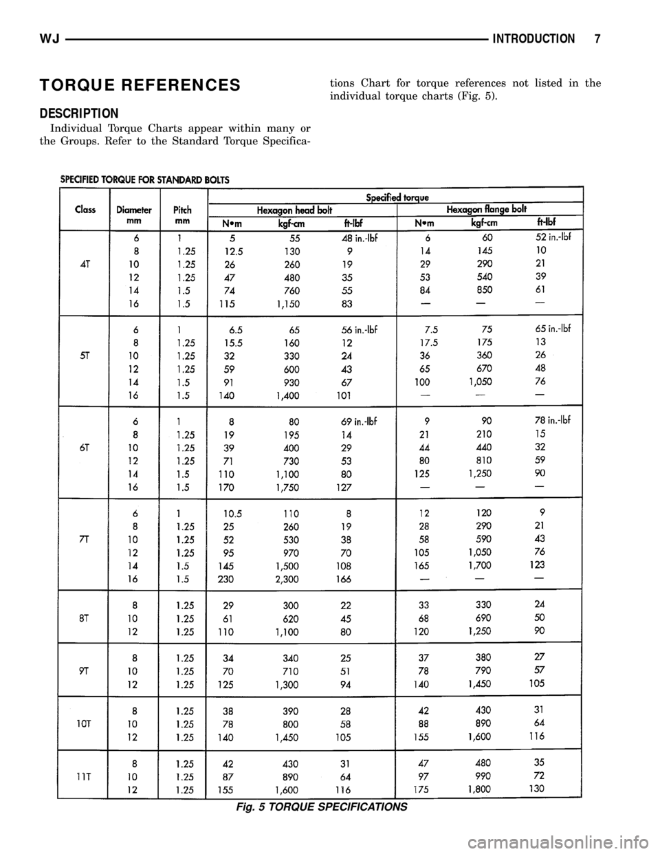
Individual Torque Charts appear within many or
the Groups. Refer to the Standard Torque Specifica-tions Chart for torque references not listed in the
individual torque charts (Fig. 5).
Fig. 5 TORQUE SPECIFICATIONS
WJINTRODUCTION 7
Page 24 of 2199
WHEEL ALIGNMENT
TABLE OF CONTENTS
page page
WHEEL ALIGNMENT
DESCRIPTION..........................3
OPERATION............................3
STANDARD PROCEDURE
STANDARD PROCEDURE - CAMBER.......3STANDARD PROCEDURE - CASTER.......4
STANDARD PROCEDURE - TOE POSITION . . 4
SPECIFICATIONS
ALIGNMENT..........................5
WHEEL ALIGNMENT
DESCRIPTION
Wheel alignment involves the correct positioning of
the wheels in relation to the vehicle. The positioning
is accomplished through suspension and steering
linkage adjustments. An alignment is considered
essential for efficient steering, good directional stabil-
ity and to minimize tire wear. The most important
measurements of an alignment are caster, camber
and toe position (Fig. 1).
CAUTION: Never attempt to modify suspension or
steering components by heating or bending.
CAUTION: Components attached with a nut and cot-
ter pin must be torqued to specification. Then if the
slot in the nut does not line up with the cotter pin
hole, tighten nut until it is aligned. Never loosen the
nut to align the cotter pin hole.
NOTE: Periodic lubrication of the front suspension/
steering system components may be required. Rub-
ber bushings must never be lubricated, Refer to
Lubrication And Maintenance for the recommended
maintenance schedule.
OPERATION
²CASTERis the forward or rearward tilt of the
steering knuckle from vertical. Tilting the top of the
knuckle rearward provides positive caster. Tilting the
top of the knuckle forward provides negative caster.
Caster is a directional stability angle. This angle
enables the front wheels to return to a straight
ahead position after turns (Fig. 1).
²CAMBERis the inward or outward tilt of the
wheel relative to the center of the vehicle. Tilting the
top of the wheel inward provides negative camber.
Tilting the top of the wheel outward provides positive
camber. Incorrect camber will cause wear on theinside or outside edge of the tire. The angle is not
adjustable, damaged component(s) must be replaced
to correct the camber angle (Fig. 1).
²WHEEL TOE POSITIONis the difference
between the leading inside edges and trailing inside
edges of the front tires. Incorrect wheel toe position
is the most common cause of unstable steering and
uneven tire wear. The wheel toe position is thefinal
front wheel alignment adjustment (Fig. 1).
²STEERING AXIS INCLINATION ANGLEis
measured in degrees and is the angle that the steer-
ing knuckles are tilted. The inclination angle has a
fixed relationship with the camber angle. It will not
change except when a spindle or ball stud is dam-
aged or bent. The angle is not adjustable, damaged
component(s) must be replaced to correct the steering
axis inclination angle.
²THRUST ANGLEis the angle of the rear axle
relative to the centerline of the vehicle. Incorrect
thrust angle can cause off-center steering and exces-
sive tire wear. This angle is not adjustable, damaged
component(s) must be replaced to correct the thrust
angle (Fig. 1).
STANDARD PROCEDURE
STANDARD PROCEDURE - CAMBER
Before each alignment reading the vehicle should
be jounced (rear first, then front). Grasp each
bumper at the center and jounce the vehicle up and
down three times. Always release the bumper in the
down position.
To obtain an accurate alignment, a 4 wheel align-
ment machine must be used and the equipment cali-
bration verified.
The wheel camber angle is preset. This angle is not
adjustable and cannot be altered.
WJWHEEL ALIGNMENT 2 - 3
Page 27 of 2199
FRONT
TABLE OF CONTENTS
page page
FRONT
DESCRIPTION..........................6
STANDARD PROCEDURE - SERVICE
WARNINGS AND CAUTIONS..............6
SPECIFICATIONS
TORQUE CHART......................7
SPECIAL TOOLS
FRONT SUSPENSION...................8
BUSHINGS
REMOVAL.............................9
INSTALLATION..........................9
HUB / BEARING
DESCRIPTION..........................9
OPERATION............................9
REMOVAL.............................9
INSTALLATION.........................10
KNUCKLE
DESCRIPTION.........................10
OPERATION...........................10
REMOVAL - STEERING KNUCKLE..........10
INSTALLATION.........................10
LOWER BALL JOINT
REMOVAL.............................11
LOWER CONTROL ARM
DESCRIPTION.........................11
OPERATION...........................11
REMOVAL.............................11
INSTALLATION.........................11SHOCK
DESCRIPTION.........................12
OPERATION...........................12
REMOVAL.............................12
INSTALLATION.........................12
SPRING
DESCRIPTION.........................12
OPERATION...........................13
REMOVAL.............................13
INSTALLATION.........................13
STABILIZER BAR
DESCRIPTION.........................14
OPERATION...........................14
REMOVAL.............................14
INSTALLATION.........................14
TRACK BAR
DESCRIPTION.........................14
OPERATION...........................14
REMOVAL.............................14
INSTALLATION.........................14
UPPER BALL JOINT
REMOVAL.............................15
UPPER CONTROL ARM
DESCRIPTION.........................16
OPERATION...........................16
REMOVAL.............................16
INSTALLATION.........................16
FRONT
DESCRIPTION
The front suspension (Fig. 1) is a link/coil design
comprised of :
²Drive axle
²Shock absorbers
²Coil springs
²Upper and lower suspension arms
²Stabilizer bar
²Track bar
²Jounce bumpers
CAUTION: Components attached with a nut and cot-
ter pin must be torqued to specification. Then if the
slot in the nut does not line up with the cotter pin
hole, tighten nut until it is aligned. Never loosen the
nut to align the cotter pin hole.CAUTION: Suspension components with rubber
bushings must be tightened with the vehicle at nor-
mal ride height. It is important to have the springs
supporting the weight of the vehicle when the fas-
teners are torqued. If springs are not at their normal
ride position, vehicle ride comfort will be affected
and cause premature bushing wear.
STANDARD PROCEDURE - SERVICE
WARNINGS AND CAUTIONS
CAUTION: Suspension components with rubber
bushings must be tightened with the vehicle at nor-
mal ride height. It is important to have the springs
supporting the weight of the vehicle when the fas-
teners are torqued. If springs are not at their normal
ride position, vehicle ride comfort will be affected
and cause premature bushing wear.
2 - 6 FRONTWJ
Page 28 of 2199
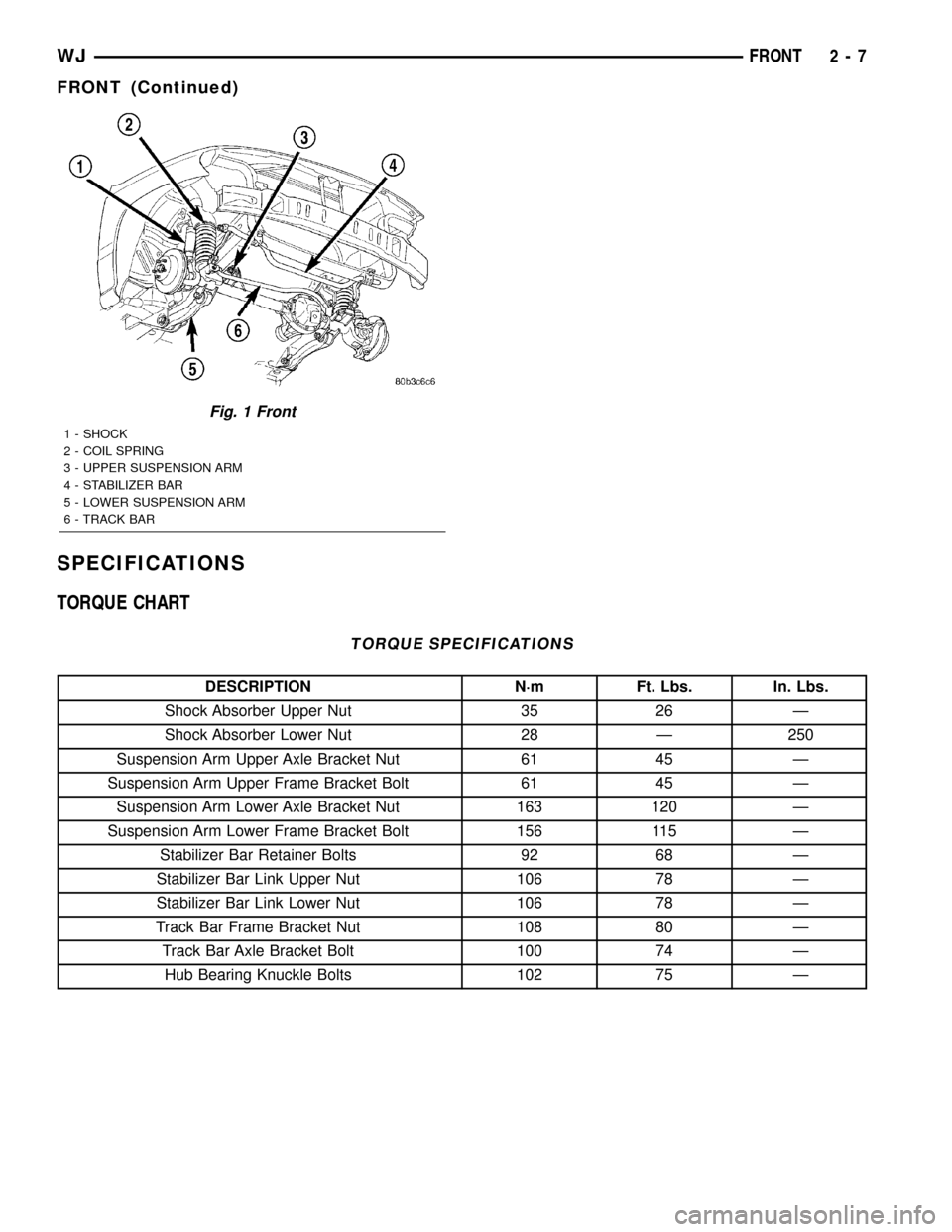
SPECIFICATIONS
TORQUE CHART
TORQUE SPECIFICATIONS
DESCRIPTION N´m Ft. Lbs. In. Lbs.
Shock Absorber Upper Nut 35 26 Ð
Shock Absorber Lower Nut 28 Ð 250
Suspension Arm Upper Axle Bracket Nut 61 45 Ð
Suspension Arm Upper Frame Bracket Bolt 61 45 Ð
Suspension Arm Lower Axle Bracket Nut 163 120 Ð
Suspension Arm Lower Frame Bracket Bolt 156 115 Ð
Stabilizer Bar Retainer Bolts 92 68 Ð
Stabilizer Bar Link Upper Nut 106 78 Ð
Stabilizer Bar Link Lower Nut 106 78 Ð
Track Bar Frame Bracket Nut 108 80 Ð
Track Bar Axle Bracket Bolt 100 74 Ð
Hub Bearing Knuckle Bolts 102 75 Ð
Fig. 1 Front
1 - SHOCK
2 - COIL SPRING
3 - UPPER SUSPENSION ARM
4 - STABILIZER BAR
5 - LOWER SUSPENSION ARM
6 - TRACK BAR
WJFRONT 2 - 7
FRONT (Continued)
Page 38 of 2199
REAR
TABLE OF CONTENTS
page page
REAR
DESCRIPTION.........................17
WARNING.............................17
DIAGNOSIS AND TESTING - REAR
SUSPENSION........................18
SPECIFICATIONS
TORQUE CHART......................18
SPECIAL TOOLS
REAR SUSPENSION...................19
LOWER CONTROL ARM
DESCRIPTION.........................19
OPERATION...........................19
REMOVAL.............................19
INSTALLATION.........................19
SHOCK
DESCRIPTION.........................19
OPERATION...........................19
REMOVAL.............................19
INSTALLATION.........................19
SPRING
DESCRIPTION.........................20OPERATION...........................20
REMOVAL.............................20
INSTALLATION.........................20
STABILIZER BAR
DESCRIPTION.........................21
OPERATION...........................21
REMOVAL.............................21
INSTALLATION.........................21
UPPER BALL JOINT
DESCRIPTION - UPPER SUSPENSION ARM,
BUSHINGS, AND BALL JOINT............21
OPERATION - UPPER SUSPENSION ARM,
BUSHINGS, AND BALL JOINT............21
REMOVAL.............................21
INSTALLATION.........................22
UPPER CONTROL ARM
DESCRIPTION.........................22
OPERATION...........................22
REMOVAL.............................22
INSTALLATION.........................23
REAR
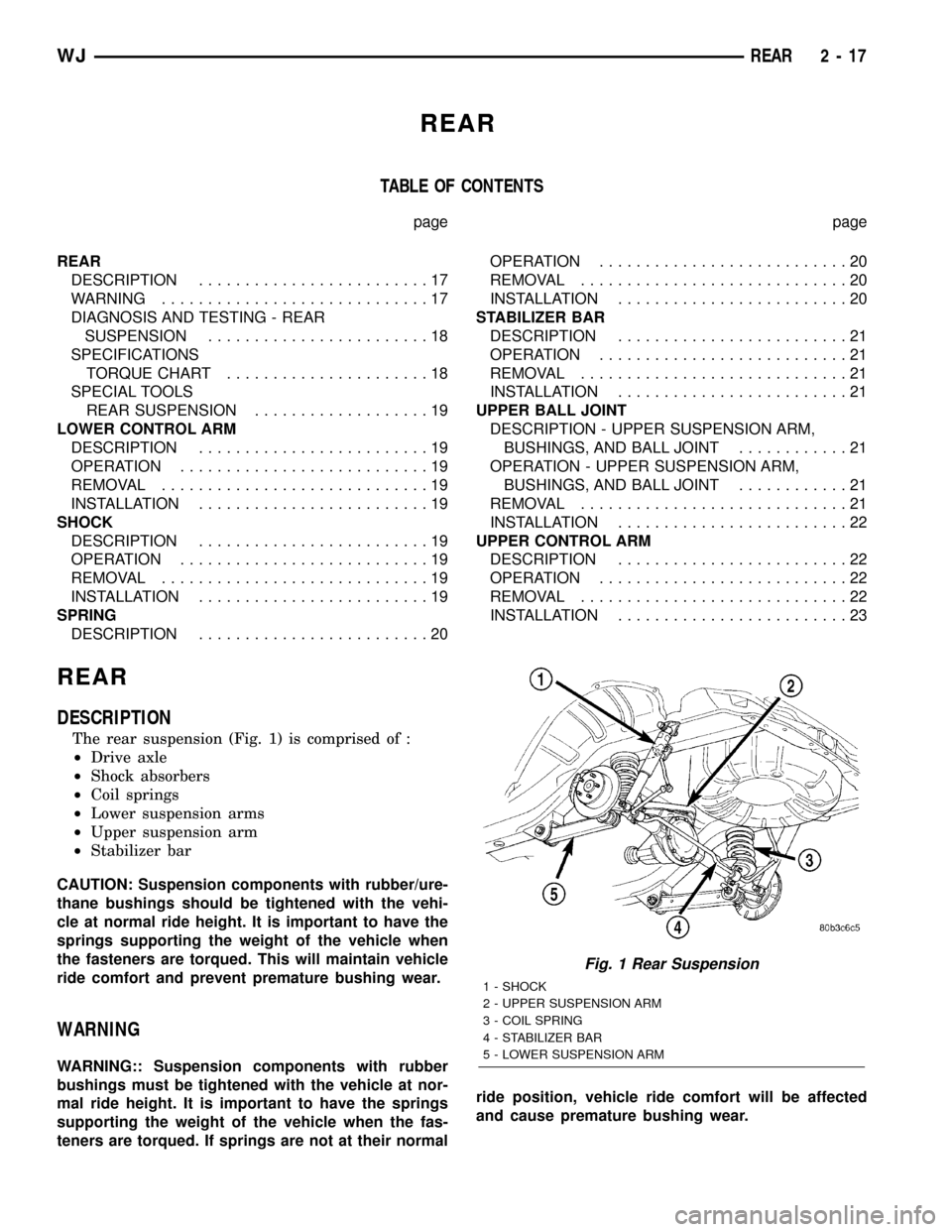
DESCRIPTION
The rear suspension (Fig. 1) is comprised of :
²Drive axle
²Shock absorbers
²Coil springs
²Lower suspension arms
²Upper suspension arm
²Stabilizer bar
CAUTION: Suspension components with rubber/ure-
thane bushings should be tightened with the vehi-
cle at normal ride height. It is important to have the
springs supporting the weight of the vehicle when
the fasteners are torqued. This will maintain vehicle
ride comfort and prevent premature bushing wear.
WARNING
WARNING:: Suspension components with rubber
bushings must be tightened with the vehicle at nor-
mal ride height. It is important to have the springs
supporting the weight of the vehicle when the fas-
teners are torqued. If springs are not at their normalride position, vehicle ride comfort will be affected
and cause premature bushing wear.
Fig. 1 Rear Suspension
1 - SHOCK
2 - UPPER SUSPENSION ARM
3 - COIL SPRING
4 - STABILIZER BAR
5 - LOWER SUSPENSION ARM
WJREAR 2 - 17
Page 39 of 2199
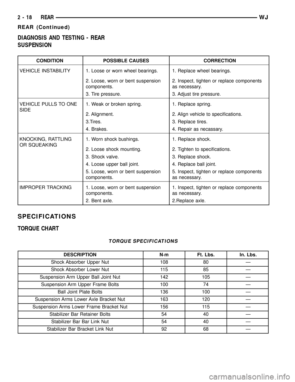
DIAGNOSIS AND TESTING - REAR
SUSPENSION
CONDITION POSSIBLE CAUSES CORRECTION
VEHICLE INSTABILITY 1. Loose or worn wheel bearings. 1. Replace wheel bearings.
2. Loose, worn or bent suspension
components.2. Inspect, tighten or replace components
as necessary.
3. Tire pressure. 3. Adjust tire pressure.
VEHICLE PULLS TO ONE
SIDE1. Weak or broken spring. 1. Replace spring.
2. Alignment. 2. Align vehicle to specifications.
3.Tires. 3. Replace tires.
4. Brakes. 4. Repair as necassary.
KNOCKING, RATTLING
OR SQUEAKING1. Worn shock bushings. 1. Replace shock.
2. Loose shock mounting. 2. Tighten to specifications.
3. Shock valve. 3. Replace shock.
4. Loose upper ball joint. 4. Replace ball joint.
5. Loose, worn or bent suspension
components.5. Inspect, tighten or replace components
as necessary.
IMPROPER TRACKING 1. Loose, worn or bent suspension
components.1. Inspect, tighten or replace components
as necessary.
2. Bent axle. 2.Replace axle.
SPECIFICATIONS
TORQUE CHART
TORQUE SPECIFICATIONS
DESCRIPTION N´m Ft. Lbs. In. Lbs.
Shock Absorber Upper Nut 108 80 Ð
Shock Absorber Lower Nut 115 85 Ð
Suspension Arm Upper Ball Joint Nut 142 105 Ð
Suspension Arm Upper Frame Bolts 100 74 Ð
Ball Joint Plate Bolts 136 100 Ð
Suspension Arms Lower Axle Bracket Nut 163 120 Ð
Suspension Arms Lower Frame Bracket Nut 156 115 Ð
Stabilizer Bar Retainer Bolts 54 40 Ð
Stabilizer Bar Bar Link Nut 54 40 Ð
Stabilizer Bar Bracket Link Nut 92 68 Ð
2 - 18 REARWJ
REAR (Continued)
Page 50 of 2199
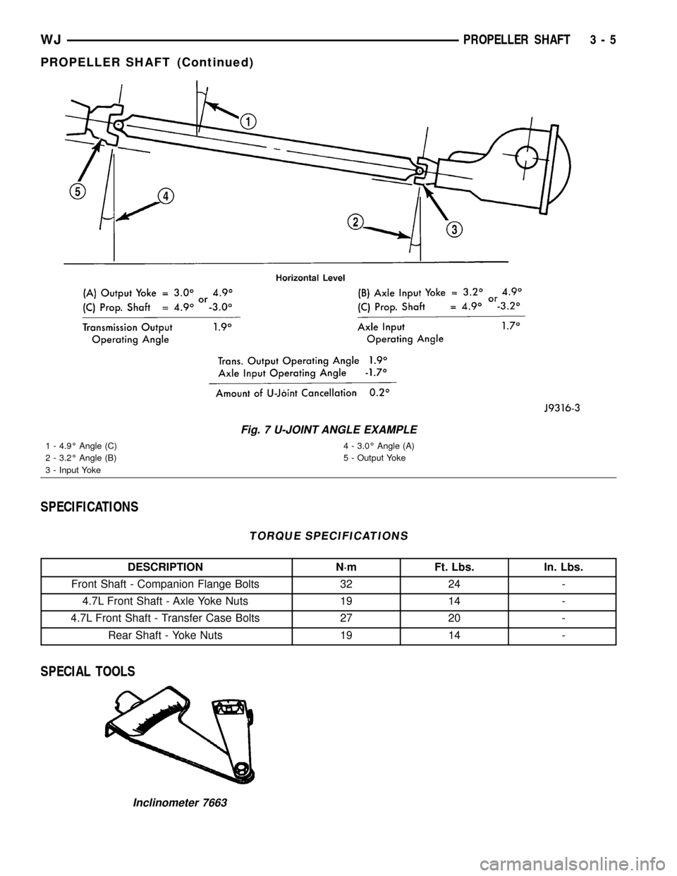
SPECIFICATIONS
TORQUE SPECIFICATIONS
DESCRIPTION N´m Ft. Lbs. In. Lbs.
Front Shaft - Companion Flange Bolts 32 24 -
4.7L Front Shaft - Axle Yoke Nuts 19 14 -
4.7L Front Shaft - Transfer Case Bolts 27 20 -
Rear Shaft - Yoke Nuts 19 14 -
SPECIAL TOOLS
Fig. 7 U-JOINT ANGLE EXAMPLE
1 - 4.9É Angle (C)
2 - 3.2É Angle (B)
3 - Input Yoke4 - 3.0É Angle (A)
5 - Output Yoke
Inclinometer 7663
WJPROPELLER SHAFT 3 - 5
PROPELLER SHAFT (Continued)
Page 60 of 2199
FRONT AXLE - 186FBI
TABLE OF CONTENTS
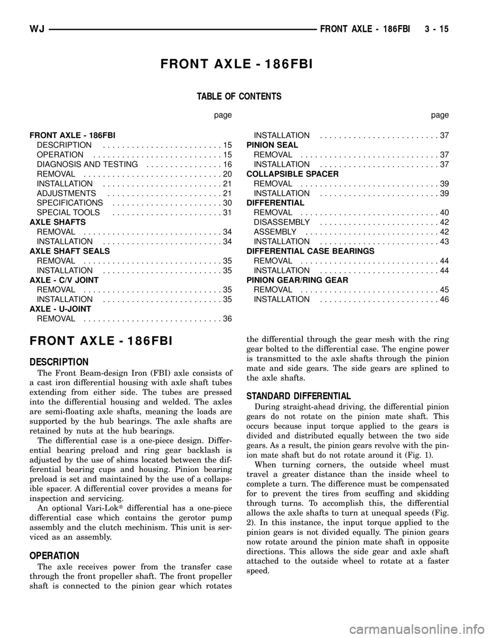
page page
FRONT AXLE - 186FBI
DESCRIPTION.........................15
OPERATION...........................15
DIAGNOSIS AND TESTING................16
REMOVAL.............................20
INSTALLATION.........................21
ADJUSTMENTS........................21
SPECIFICATIONS.......................30
SPECIAL TOOLS.......................31
AXLE SHAFTS
REMOVAL.............................34
INSTALLATION.........................34
AXLE SHAFT SEALS
REMOVAL.............................35
INSTALLATION.........................35
AXLE - C/V JOINT
REMOVAL.............................35
INSTALLATION.........................35
AXLE - U-JOINT
REMOVAL.............................36INSTALLATION.........................37
PINION SEAL
REMOVAL.............................37
INSTALLATION.........................37
COLLAPSIBLE SPACER
REMOVAL.............................39
INSTALLATION.........................39
DIFFERENTIAL
REMOVAL.............................40
DISASSEMBLY.........................42
ASSEMBLY............................42
INSTALLATION.........................43
DIFFERENTIAL CASE BEARINGS
REMOVAL.............................44
INSTALLATION.........................44
PINION GEAR/RING GEAR
REMOVAL.............................45
INSTALLATION.........................46
FRONT AXLE - 186FBI
DESCRIPTION
The Front Beam-design Iron (FBI) axle consists of
a cast iron differential housing with axle shaft tubes
extending from either side. The tubes are pressed
into the differential housing and welded. The axles
are semi-floating axle shafts, meaning the loads are
supported by the hub bearings. The axle shafts are
retained by nuts at the hub bearings.
The differential case is a one-piece design. Differ-
ential bearing preload and ring gear backlash is
adjusted by the use of shims located between the dif-
ferential bearing cups and housing. Pinion bearing
preload is set and maintained by the use of a collaps-
ible spacer. A differential cover provides a means for
inspection and servicing.
An optional Vari-Loktdifferential has a one-piece
differential case which contains the gerotor pump
assembly and the clutch mechinism. This unit is ser-
viced as an assembly.
OPERATION
The axle receives power from the transfer case
through the front propeller shaft. The front propeller
shaft is connected to the pinion gear which rotatesthe differential through the gear mesh with the ring
gear bolted to the differential case. The engine power
is transmitted to the axle shafts through the pinion
mate and side gears. The side gears are splined to
the axle shafts.
STANDARD DIFFERENTIAL
During straight-ahead driving, the differential pinion
gears do not rotate on the pinion mate shaft. This
occurs because input torque applied to the gears is
divided and distributed equally between the two side
gears. As a result, the pinion gears revolve with the pin-
ion mate shaft but do not rotate around it (Fig. 1).
When turning corners, the outside wheel must
travel a greater distance than the inside wheel to
complete a turn. The difference must be compensated
for to prevent the tires from scuffing and skidding
through turns. To accomplish this, the differential
allows the axle shafts to turn at unequal speeds (Fig.
2). In this instance, the input torque applied to the
pinion gears is not divided equally. The pinion gears
now rotate around the pinion mate shaft in opposite
directions. This allows the side gear and axle shaft
attached to the outside wheel to rotate at a faster
speed.
WJFRONT AXLE - 186FBI 3 - 15
Page 75 of 2199
DIFFERENTIAL BEARING PRELOAD CHECK
The final check on the differential assembly before
installing the axles is torque to rotate pinion and dif-
ferential combined. This will verify the correct differ-
ential bearing preload.Torque to rotate the differential and pinion should
be the torque to rotate the pinion plus 0.79-1.24 N´m
(7-11 in. lbs.).
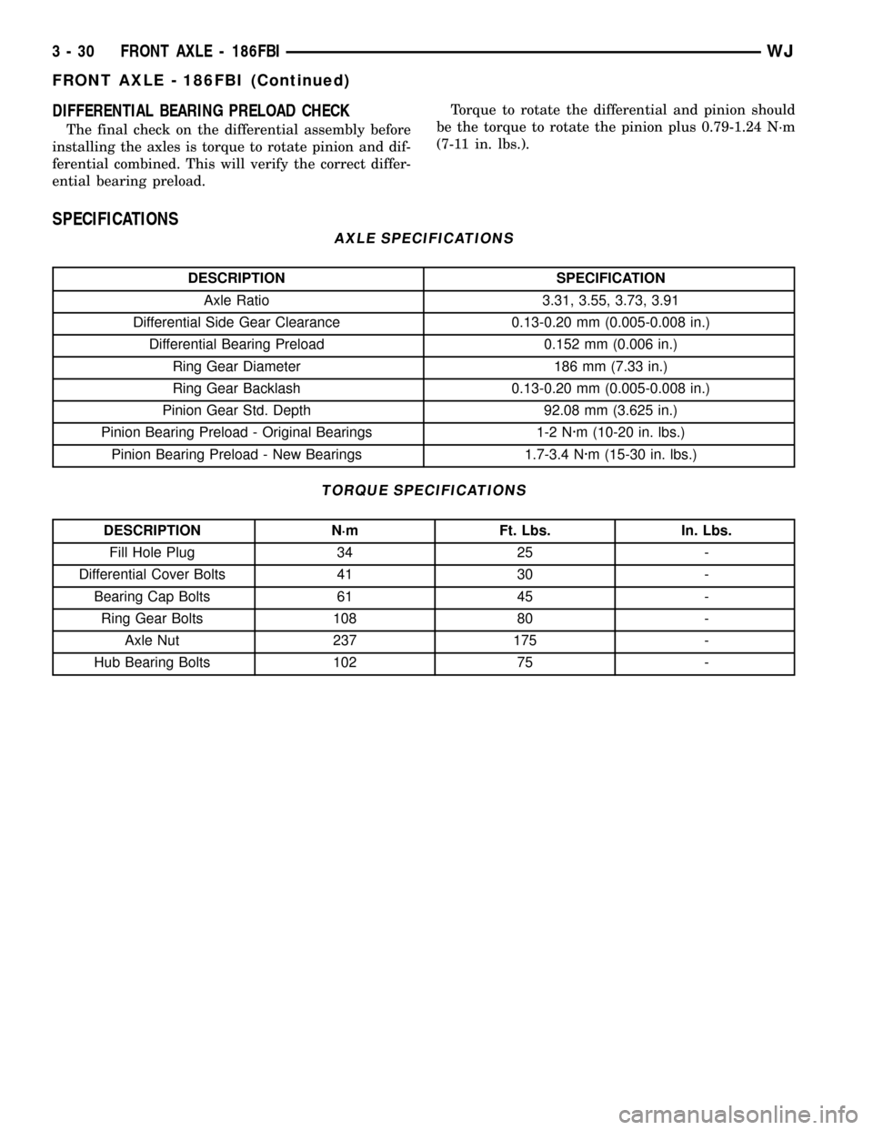
SPECIFICATIONS
AXLE SPECIFICATIONS
DESCRIPTION SPECIFICATION
Axle Ratio 3.31, 3.55, 3.73, 3.91
Differential Side Gear Clearance 0.13-0.20 mm (0.005-0.008 in.)
Differential Bearing Preload 0.152 mm (0.006 in.)
Ring Gear Diameter 186 mm (7.33 in.)
Ring Gear Backlash 0.13-0.20 mm (0.005-0.008 in.)
Pinion Gear Std. Depth 92.08 mm (3.625 in.)
Pinion Bearing Preload - Original Bearings 1-2 N´m (10-20 in. lbs.)
Pinion Bearing Preload - New Bearings 1.7-3.4 N´m (15-30 in. lbs.)
TORQUE SPECIFICATIONS
DESCRIPTION N´m Ft. Lbs. In. Lbs.
Fill Hole Plug 34 25 -
Differential Cover Bolts 41 30 -
Bearing Cap Bolts 61 45 -
Ring Gear Bolts 108 80 -
Axle Nut 237 175 -
Hub Bearing Bolts 102 75 -
3 - 30 FRONT AXLE - 186FBIWJ
FRONT AXLE - 186FBI (Continued)