torque specifications JEEP GRAND CHEROKEE 2002 WJ / 2.G User Guide
[x] Cancel search | Manufacturer: JEEP, Model Year: 2002, Model line: GRAND CHEROKEE, Model: JEEP GRAND CHEROKEE 2002 WJ / 2.GPages: 2199, PDF Size: 76.01 MB
Page 95 of 2199

REAR AXLE - 198RBI
TABLE OF CONTENTS
page page
REAR AXLE - 198RBI
DESCRIPTION.........................50
OPERATION...........................50
DIAGNOSIS AND TESTING................51
REMOVAL.............................55
INSTALLATION.........................56
ADJUSTMENTS........................56
SPECIFICATIONS.......................65
SPECIAL TOOLS.......................66
AXLE SHAFTS
REMOVAL.............................69
INSTALLATION.........................69
AXLE BEARINGS/SEALS
REMOVAL.............................69
INSTALLATION.........................70
PINION SEAL
REMOVAL.............................71
INSTALLATION.........................71
COLLAPSIBLE SPACER
REMOVAL.............................73INSTALLATION.........................73
DIFFERENTIAL
REMOVAL.............................75
DISASSEMBLY.........................77
ASSEMBLY............................77
INSTALLATION.........................77
DIFFERENTIAL-TRAC-LOC
DIAGNOSIS AND TESTING................79
DISASSEMBLY.........................79
CLEANING............................82
INSPECTION..........................82
ASSEMBLY............................82
DIFFERENTIAL CASE BEARINGS
REMOVAL.............................83
INSTALLATION.........................84
PINION GEAR/RING GEAR
REMOVAL.............................84
INSTALLATION.........................86
REAR AXLE - 198RBI
DESCRIPTION
The Rear Beam-design Iron (RBI) axle housing has
an iron center casting with axle shaft tubes extend-
ing from either side. The tubes are pressed into and
welded to the differential housing to form a one-piece
axle housing. The axles has semi-floating axle shafts,
meaning that loads are supported by the axle shaft
and bearings. The axle shafts are retained by bearing
retainer plates on the axles which are bolted to
flanges at the outboard end of the axle tubes.
The differential case is a one-piece design. Differ-
ential bearing preload and ring gear backlash is
adjusted by the use of selective spacer shims. Pinion
bearing preload is set and maintained by the use of a
collapsible spacer. A differential cover provides a
means for inspection and service.
Axles with optional Trac-Loktdifferential have a
one-piece differential case, and the same internal
components as a standard differential, plus two
clutch disc packs.
OPERATION
The axle receives power from the transmission/
transfer case through the rear propeller shaft. Therear propeller shaft is connected to the pinion gear
which rotates the differential through the gear mesh
with the ring gear bolted to the differential case. The
engine power is transmitted to the axle shafts
through the pinion mate and side gears. The side
gears are splined to the axle shafts.
STANDARD DIFFERENTIAL
During straight-ahead driving, the differential pin-
ion gears do not rotate on the pinion mate shaft. This
occurs because input torque applied to the gears is
divided and distributed equally between the two side
gears. As a result, the pinion gears revolve with the
pinion mate shaft but do not rotate around it (Fig. 1).
When turning corners, the outside wheel must
travel a greater distance than the inside wheel to
complete a turn. The difference must be compensated
for to prevent the tires from scuffing and skidding
through turns. To accomplish this, the differential
allows the axle shafts to turn at unequal speeds (Fig.
2). In this instance, the input torque applied to the
pinion gears is not divided equally. The pinion gears
now rotate around the pinion mate shaft in opposite
directions. This allows the side gear and axle shaft
attached to the outside wheel to rotate at a faster
speed.
3 - 50 REAR AXLE - 198RBIWJ
Page 110 of 2199
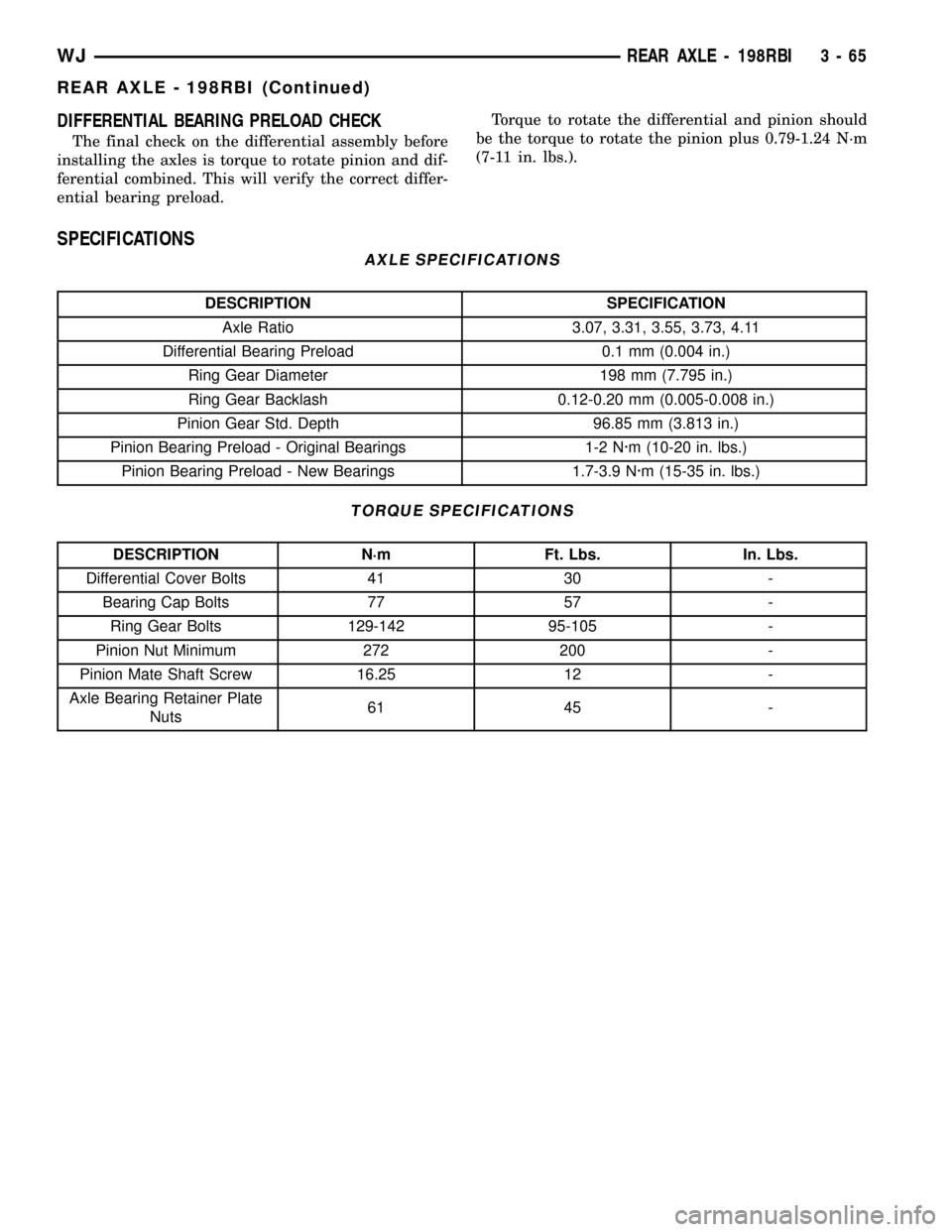
DIFFERENTIAL BEARING PRELOAD CHECK
The final check on the differential assembly before
installing the axles is torque to rotate pinion and dif-
ferential combined. This will verify the correct differ-
ential bearing preload.Torque to rotate the differential and pinion should
be the torque to rotate the pinion plus 0.79-1.24 N´m
(7-11 in. lbs.).
SPECIFICATIONS
AXLE SPECIFICATIONS
DESCRIPTION SPECIFICATION
Axle Ratio 3.07, 3.31, 3.55, 3.73, 4.11
Differential Bearing Preload 0.1 mm (0.004 in.)
Ring Gear Diameter 198 mm (7.795 in.)
Ring Gear Backlash 0.12-0.20 mm (0.005-0.008 in.)
Pinion Gear Std. Depth 96.85 mm (3.813 in.)
Pinion Bearing Preload - Original Bearings 1-2 N´m (10-20 in. lbs.)
Pinion Bearing Preload - New Bearings 1.7-3.9 N´m (15-35 in. lbs.)
TORQUE SPECIFICATIONS
DESCRIPTION N´m Ft. Lbs. In. Lbs.
Differential Cover Bolts 41 30 -
Bearing Cap Bolts 77 57 -
Ring Gear Bolts 129-142 95-105 -
Pinion Nut Minimum 272 200 -
Pinion Mate Shaft Screw 16.25 12 -
Axle Bearing Retainer Plate
Nuts61 45 -
WJREAR AXLE - 198RBI 3 - 65
REAR AXLE - 198RBI (Continued)
Page 135 of 2199

REAR AXLE - 226RBA
TABLE OF CONTENTS
page page
REAR AXLE - 226RBA
DESCRIPTION.........................90
OPERATION...........................90
DIAGNOSIS AND TESTING................92
REMOVAL.............................95
INSTALLATION.........................96
ADJUSTMENTS........................97
SPECIFICATIONS......................105
SPECIAL TOOLS.......................106
AXLE SHAFTS
REMOVAL............................109
INSTALLATION........................109
AXLE BEARINGS/SEALS
REMOVAL............................109
INSTALLATION........................110
PINION SEAL
REMOVAL............................111
INSTALLATION........................112
COLLAPSIBLE SPACER
REMOVAL............................113INSTALLATION........................114
DIFFERENTIAL
REMOVAL............................115
DISASSEMBLY........................117
ASSEMBLY...........................117
INSTALLATION........................117
DIFFERENTIAL - TRAC-LOK
DIAGNOSIS AND TESTING...............119
DISASSEMBLY........................119
CLEANING...........................121
INSPECTION.........................121
ASSEMBLY...........................121
DIFFERENTIAL CASE BEARINGS
REMOVAL............................123
INSTALLATION........................123
PINION GEAR/RING GEAR
REMOVAL............................124
INSTALLATION........................126
REAR AXLE - 226RBA
DESCRIPTION
The Rear Beam-design Aluminum (RBA) axle hous-
ing has an aluminum center casting (differential
housing) with axle shaft tubes extending from either
side. The tubes are pressed into the differential hous-
ing to form a one-piece axle housing. The axle has
semi-floating axle shafts, meaning that vehicle load
is supported by the axle shaft and bearings.
The differential case is a one-piece design. Differen-
tial bearing preload and ring gear backlash is adjusted
with selective shims. Pinion bearing preload is set and
maintained by the use of a collapsible spacer. The cover
provides a means for inspection and service.
Optional Trac-Loktdifferential differential has a
one-piece differential case, and the same internal
components as a standard differential, plus two
clutch disc packs.
Optional Vari-Loktdifferential has a one-piece dif-
ferential case which contains the gerotor pump
assembly and the clutch mechinism. The unit is ser-
viced only as an assembly.
OPERATION
The axle receives power from the transfer case
through the front propeller shaft. The front propellershaft is connected to the pinion gear which rotates
the differential through the gear mesh with the ring
gear bolted to the differential case. The engine power
is transmitted to the axle shafts through the pinion
mate and side gears. The side gears are splined to
the axle shafts.
STANDARD DIFFERENTIAL
During straight-ahead driving the differential pin-
ion gears do not rotate on the pinion mate shaft. This
occurs because input torque applied to the gears is
divided and distributed equally between the two side
gears. As a result, the pinion gears revolve with the
pinion mate shaft but do not rotate around it (Fig. 1).
When turning corners, the outside wheel must travel
a greater distance than the inside wheel to complete a
turn. The difference must be compensated for to prevent
the tires from scuffing and skidding through turns. To
accomplish this, the differential allows the axle shafts
to turn at unequal speeds (Fig. 2). In this instance, the
input torque applied to the pinion gears is not divided
equally. The pinion gears now rotate around the pinion
mate shaft in opposite directions. This allows the side
gear and axle shaft attached to the outside wheel to
rotate at a faster speed.
3 - 90 REAR AXLE - 226RBAWJ
Page 150 of 2199
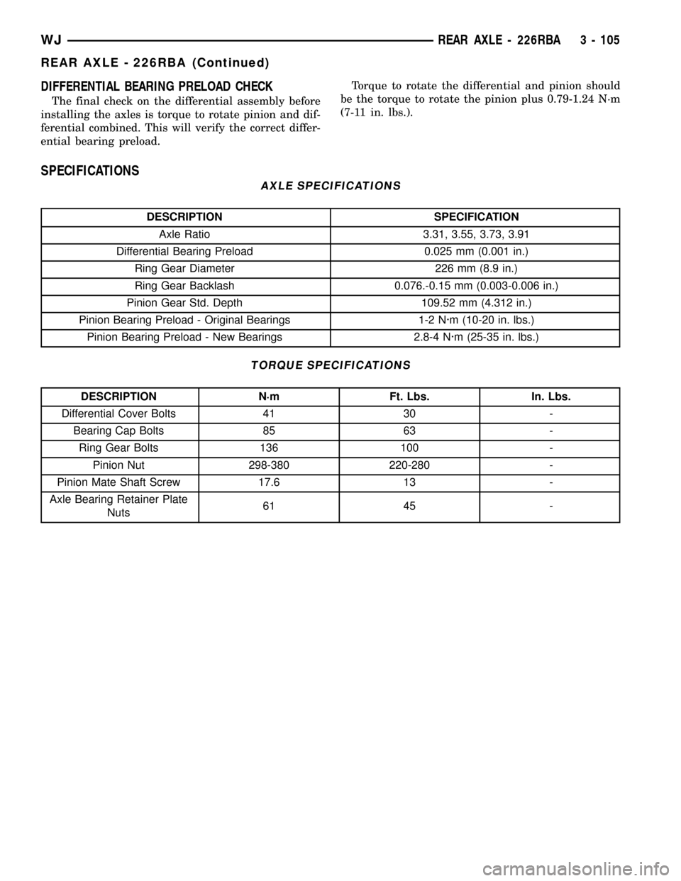
DIFFERENTIAL BEARING PRELOAD CHECK
The final check on the differential assembly before
installing the axles is torque to rotate pinion and dif-
ferential combined. This will verify the correct differ-
ential bearing preload.Torque to rotate the differential and pinion should
be the torque to rotate the pinion plus 0.79-1.24 N´m
(7-11 in. lbs.).
SPECIFICATIONS
AXLE SPECIFICATIONS
DESCRIPTION SPECIFICATION
Axle Ratio 3.31, 3.55, 3.73, 3.91
Differential Bearing Preload 0.025 mm (0.001 in.)
Ring Gear Diameter 226 mm (8.9 in.)
Ring Gear Backlash 0.076.-0.15 mm (0.003-0.006 in.)
Pinion Gear Std. Depth 109.52 mm (4.312 in.)
Pinion Bearing Preload - Original Bearings 1-2 N´m (10-20 in. lbs.)
Pinion Bearing Preload - New Bearings 2.8-4 N´m (25-35 in. lbs.)
TORQUE SPECIFICATIONS
DESCRIPTION N´m Ft. Lbs. In. Lbs.
Differential Cover Bolts 41 30 -
Bearing Cap Bolts 85 63 -
Ring Gear Bolts 136 100 -
Pinion Nut 298-380 220-280 -
Pinion Mate Shaft Screw 17.6 13 -
Axle Bearing Retainer Plate
Nuts61 45 -
WJREAR AXLE - 226RBA 3 - 105
REAR AXLE - 226RBA (Continued)
Page 176 of 2199
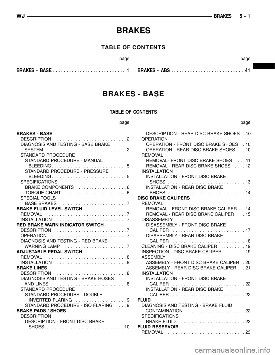
BRAKES
TABLE OF CONTENTS
page page
BRAKES - BASE........................... 1BRAKES - ABS........................... 41
BRAKES - BASE
TABLE OF CONTENTS
page page
BRAKES - BASE
DESCRIPTION..........................2
DIAGNOSIS AND TESTING - BASE BRAKE
SYSTEM.............................2
STANDARD PROCEDURE
STANDARD PROCEDURE - MANUAL
BLEEDING............................5
STANDARD PROCEDURE - PRESSURE
BLEEDING............................5
SPECIFICATIONS
BRAKE COMPONENTS..................6
TORQUE CHART......................6
SPECIAL TOOLS
BASE BRAKES........................7
BRAKE FLUID LEVEL SWITCH
REMOVAL.............................7
INSTALLATION..........................7
RED BRAKE WARN INDICATOR SWITCH
DESCRIPTION..........................7
OPERATION............................7
DIAGNOSIS AND TESTING - RED BRAKE
WARNING LAMP.......................7
ADJUSTABLE PEDAL SWITCH
REMOVAL.............................8
INSTALLATION..........................8
BRAKE LINES
DESCRIPTION..........................8
DIAGNOSIS AND TESTING - BRAKE HOSES
AND LINES...........................8
STANDARD PROCEDURE
STANDARD PROCEDURE - DOUBLE
INVERTED FLARING....................9
STANDARD PROCEDURE - ISO FLARING . . . 9
BRAKE PADS / SHOES
DESCRIPTION
DESCRIPTION - FRONT DISC BRAKE
SHOES.............................10DESCRIPTION - REAR DISC BRAKE SHOES . 10
OPERATION
OPERATION - FRONT DISC BRAKE SHOES . 10
OPERATION - REAR DISC BRAKE SHOES . . 10
REMOVAL
REMOVAL- FRONT DISC BRAKE SHOES . . . 11
REMOVAL - REAR DISC BRAKE SHOES....12
INSTALLATION
INSTALLATION - FRONT DISC BRAKE
SHOES.............................13
INSTALLATION - REAR DISC BRAKE
SHOES.............................14
DISC BRAKE CALIPERS
REMOVAL
REMOVAL - FRONT DISC BRAKE CALIPER . 14
REMOVAL - REAR DISC BRAKE CALIPER . . 15
DISASSEMBLY
DISASSEMBLY - FRONT DISC BRAKE
CALIPER............................17
DISASSEMBLY - REAR DISC BRAKE
CALIPER............................18
CLEANING - DISC BRAKE CALIPER.........19
INSPECTION - DISC BRAKE CALIPER.......19
ASSEMBLY
ASSEMBLY - FRONT DISC BRAKE CALIPER . 20
ASSEMBLY - REAR DISC BRAKE CALIPER . 21
INSTALLATION
INSTALLATION - FRONT DISC BRAKE
CALIPER............................22
INSTALLATION - REAR DISC BRAKE
CALIPER............................22
FLUID
DIAGNOSIS AND TESTING - BRAKE FLUID
CONTAMINATION.....................22
SPECIFICATIONS
BRAKE FLUID........................23
FLUID RESERVOIR
REMOVAL.............................23
WJBRAKES 5 - 1
Page 181 of 2199
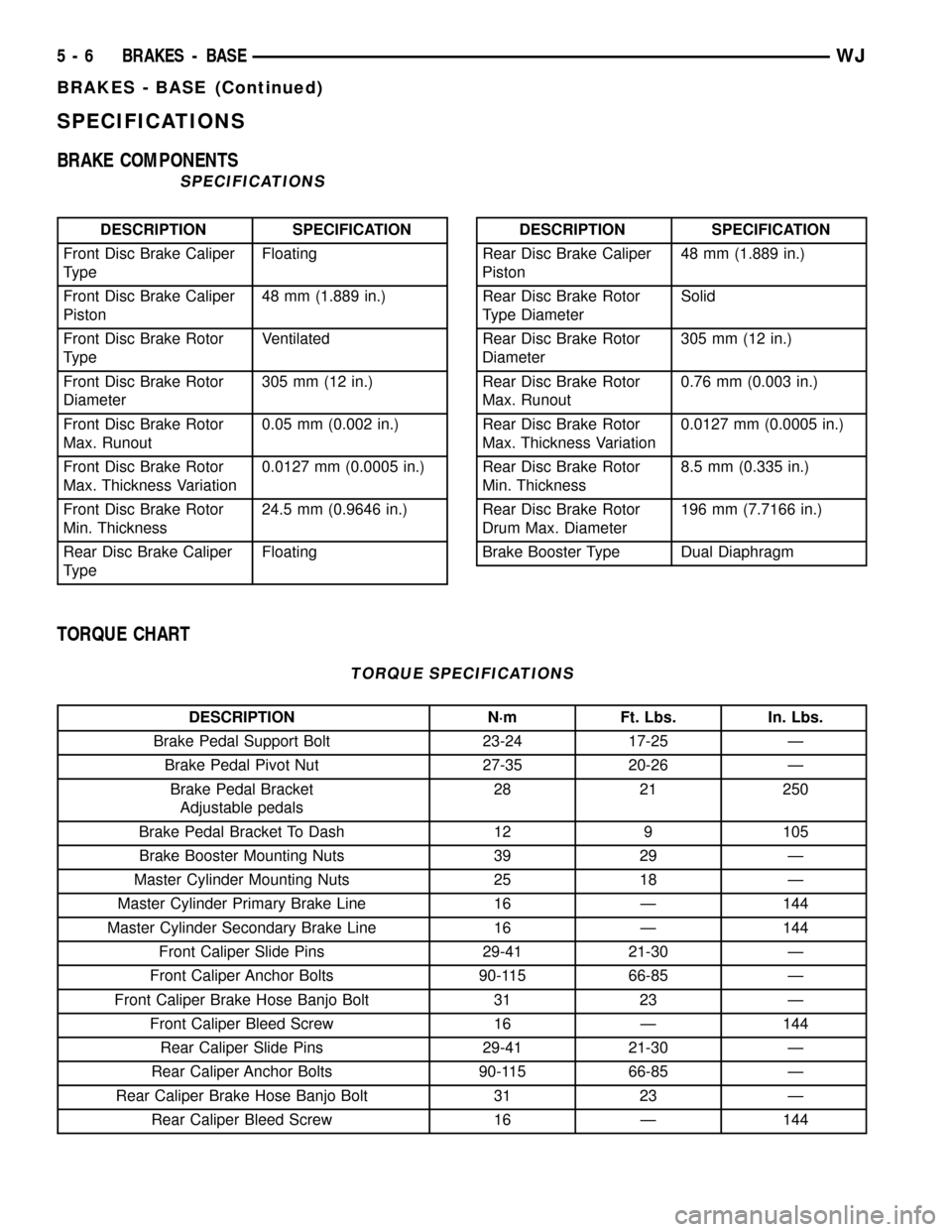
SPECIFICATIONS
BRAKE COMPONENTS
SPECIFICATIONS
DESCRIPTION SPECIFICATION
Front Disc Brake Caliper
TypeFloating
Front Disc Brake Caliper
Piston48 mm (1.889 in.)
Front Disc Brake Rotor
TypeVentilated
Front Disc Brake Rotor
Diameter305 mm (12 in.)
Front Disc Brake Rotor
Max. Runout0.05 mm (0.002 in.)
Front Disc Brake Rotor
Max. Thickness Variation0.0127 mm (0.0005 in.)
Front Disc Brake Rotor
Min. Thickness24.5 mm (0.9646 in.)
Rear Disc Brake Caliper
TypeFloatingDESCRIPTION SPECIFICATION
Rear Disc Brake Caliper
Piston48 mm (1.889 in.)
Rear Disc Brake Rotor
Type DiameterSolid
Rear Disc Brake Rotor
Diameter305 mm (12 in.)
Rear Disc Brake Rotor
Max. Runout0.76 mm (0.003 in.)
Rear Disc Brake Rotor
Max. Thickness Variation0.0127 mm (0.0005 in.)
Rear Disc Brake Rotor
Min. Thickness8.5 mm (0.335 in.)
Rear Disc Brake Rotor
Drum Max. Diameter196 mm (7.7166 in.)
Brake Booster Type Dual Diaphragm
TORQUE CHART
TORQUE SPECIFICATIONS
DESCRIPTION N´m Ft. Lbs. In. Lbs.
Brake Pedal Support Bolt 23-24 17-25 Ð
Brake Pedal Pivot Nut 27-35 20-26 Ð
Brake Pedal Bracket
Adjustable pedals28 21 250
Brake Pedal Bracket To Dash 12 9 105
Brake Booster Mounting Nuts 39 29 Ð
Master Cylinder Mounting Nuts 25 18 Ð
Master Cylinder Primary Brake Line 16 Ð 144
Master Cylinder Secondary Brake Line 16 Ð 144
Front Caliper Slide Pins 29-41 21-30 Ð
Front Caliper Anchor Bolts 90-115 66-85 Ð
Front Caliper Brake Hose Banjo Bolt 31 23 Ð
Front Caliper Bleed Screw 16 Ð 144
Rear Caliper Slide Pins 29-41 21-30 Ð
Rear Caliper Anchor Bolts 90-115 66-85 Ð
Rear Caliper Brake Hose Banjo Bolt 31 23 Ð
Rear Caliper Bleed Screw 16 Ð 144
5 - 6 BRAKES - BASEWJ
BRAKES - BASE (Continued)
Page 216 of 2199
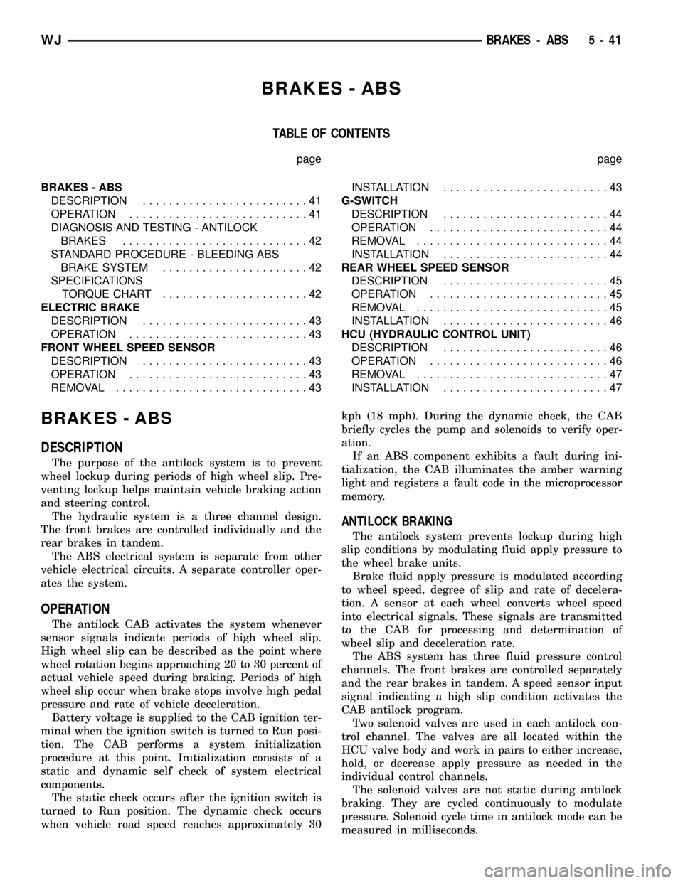
BRAKES - ABS
TABLE OF CONTENTS
page page
BRAKES - ABS
DESCRIPTION.........................41
OPERATION...........................41
DIAGNOSIS AND TESTING - ANTILOCK
BRAKES............................42
STANDARD PROCEDURE - BLEEDING ABS
BRAKE SYSTEM......................42
SPECIFICATIONS
TORQUE CHART......................42
ELECTRIC BRAKE
DESCRIPTION.........................43
OPERATION...........................43
FRONT WHEEL SPEED SENSOR
DESCRIPTION.........................43
OPERATION...........................43
REMOVAL.............................43INSTALLATION.........................43
G-SWITCH
DESCRIPTION.........................44
OPERATION...........................44
REMOVAL.............................44
INSTALLATION.........................44
REAR WHEEL SPEED SENSOR
DESCRIPTION.........................45
OPERATION...........................45
REMOVAL.............................45
INSTALLATION.........................46
HCU (HYDRAULIC CONTROL UNIT)
DESCRIPTION.........................46
OPERATION...........................46
REMOVAL.............................47
INSTALLATION.........................47
BRAKES - ABS
DESCRIPTION
The purpose of the antilock system is to prevent
wheel lockup during periods of high wheel slip. Pre-
venting lockup helps maintain vehicle braking action
and steering control.
The hydraulic system is a three channel design.
The front brakes are controlled individually and the
rear brakes in tandem.
The ABS electrical system is separate from other
vehicle electrical circuits. A separate controller oper-
ates the system.
OPERATION
The antilock CAB activates the system whenever
sensor signals indicate periods of high wheel slip.
High wheel slip can be described as the point where
wheel rotation begins approaching 20 to 30 percent of
actual vehicle speed during braking. Periods of high
wheel slip occur when brake stops involve high pedal
pressure and rate of vehicle deceleration.
Battery voltage is supplied to the CAB ignition ter-
minal when the ignition switch is turned to Run posi-
tion. The CAB performs a system initialization
procedure at this point. Initialization consists of a
static and dynamic self check of system electrical
components.
The static check occurs after the ignition switch is
turned to Run position. The dynamic check occurs
when vehicle road speed reaches approximately 30kph (18 mph). During the dynamic check, the CAB
briefly cycles the pump and solenoids to verify oper-
ation.
If an ABS component exhibits a fault during ini-
tialization, the CAB illuminates the amber warning
light and registers a fault code in the microprocessor
memory.
ANTILOCK BRAKING
The antilock system prevents lockup during high
slip conditions by modulating fluid apply pressure to
the wheel brake units.
Brake fluid apply pressure is modulated according
to wheel speed, degree of slip and rate of decelera-
tion. A sensor at each wheel converts wheel speed
into electrical signals. These signals are transmitted
to the CAB for processing and determination of
wheel slip and deceleration rate.
The ABS system has three fluid pressure control
channels. The front brakes are controlled separately
and the rear brakes in tandem. A speed sensor input
signal indicating a high slip condition activates the
CAB antilock program.
Two solenoid valves are used in each antilock con-
trol channel. The valves are all located within the
HCU valve body and work in pairs to either increase,
hold, or decrease apply pressure as needed in the
individual control channels.
The solenoid valves are not static during antilock
braking. They are cycled continuously to modulate
pressure. Solenoid cycle time in antilock mode can be
measured in milliseconds.
WJBRAKES - ABS 5 - 41
Page 217 of 2199
DIAGNOSIS AND TESTING - ANTILOCK
BRAKES
The ABS brake system performs several self-tests
every time the ignition switch is turned on and the
vehicle is driven. The CAB monitors the systems
input and output circuits to verify the system is oper-
ating correctly. If the on board diagnostic system
senses that a circuit is malfunctioning the system
will set a trouble code in its memory.
NOTE: An audible noise may be heard during the
self-test. This noise should be considered normal.
NOTE: The MDS or DRB III scan tool is used to
diagnose the ABS system. For additional informa-
tion refer to the Electrical section. For test proce-
dures refer to the Chassis Diagnostic Manual.
STANDARD PROCEDURE - BLEEDING ABS
BRAKE SYSTEM
ABS system bleeding requires conventional bleed-
ing methods plus use of the DRB scan tool. The pro-cedure involves performing a base brake bleeding,
followed by use of the scan tool to cycle and bleed the
HCU pump and solenoids. A second base brake bleed-
ing procedure is then required to remove any air
remaining in the system.
(1) Perform base brake bleeding. (Refer to 5 -
BRAKES - STANDARD PROCEDURE) OR (Refer to
5 - BRAKES - STANDARD PROCEDURE).
(2) Connect scan tool to the Data Link Connector.
(3) Select ANTILOCK BRAKES, followed by MIS-
CELLANEOUS, then ABS BRAKES. Follow the
instructions displayed. When scan tool displays TEST
COMPLETE, disconnect scan tool and proceed.
(4) Perform base brake bleeding a second time.
(Refer to 5 - BRAKES - STANDARD PROCEDURE)
OR (Refer to 5 - BRAKES - STANDARD PROCE-
DURE).
(5) Top off master cylinder fluid level and verify
proper brake operation before moving vehicle.
SPECIFICATIONS
TORQUE CHART
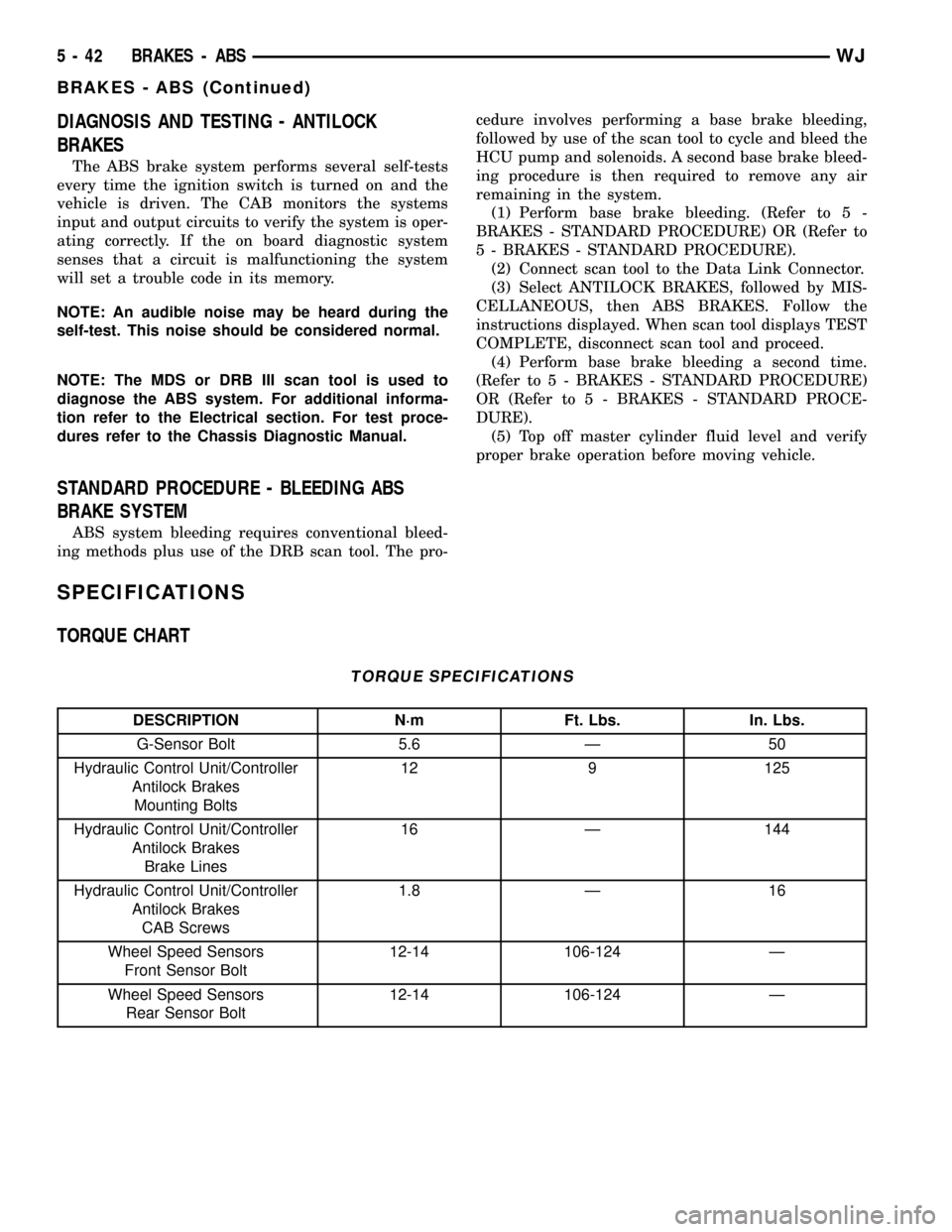
TORQUE SPECIFICATIONS
DESCRIPTION N´m Ft. Lbs. In. Lbs.
G-Sensor Bolt 5.6 Ð 50
Hydraulic Control Unit/Controller
Antilock Brakes
Mounting Bolts12 9 125
Hydraulic Control Unit/Controller
Antilock Brakes
Brake Lines16 Ð 144
Hydraulic Control Unit/Controller
Antilock Brakes
CAB Screws1.8 Ð 16
Wheel Speed Sensors
Front Sensor Bolt12-14 106-124 Ð
Wheel Speed Sensors
Rear Sensor Bolt12-14 106-124 Ð
5 - 42 BRAKES - ABSWJ
BRAKES - ABS (Continued)
Page 224 of 2199
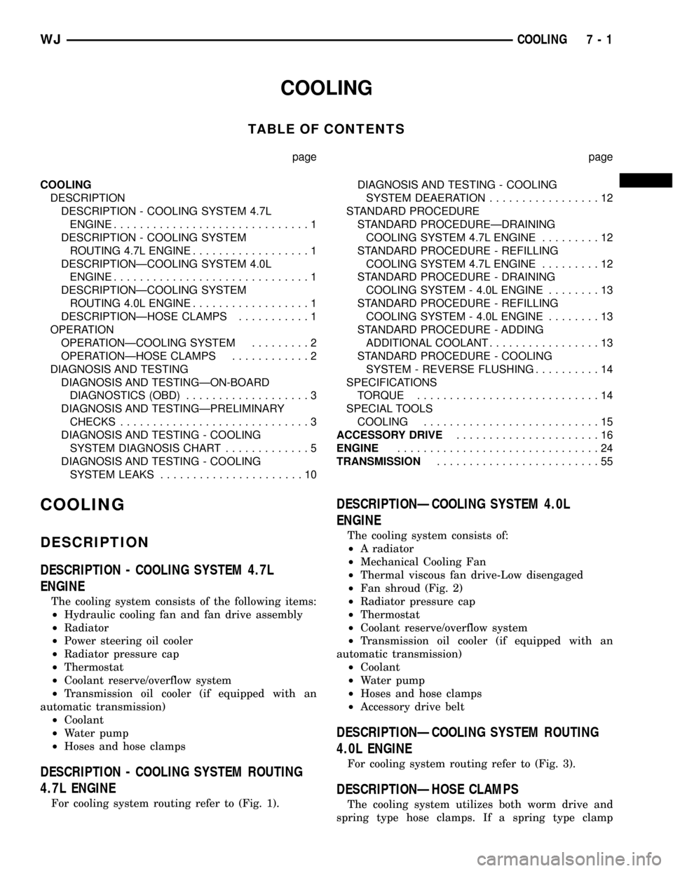
COOLING
TABLE OF CONTENTS
page page
COOLING
DESCRIPTION
DESCRIPTION - COOLING SYSTEM 4.7L
ENGINE..............................1
DESCRIPTION - COOLING SYSTEM
ROUTING 4.7L ENGINE..................1
DESCRIPTIONÐCOOLING SYSTEM 4.0L
ENGINE..............................1
DESCRIPTIONÐCOOLING SYSTEM
ROUTING 4.0L ENGINE..................1
DESCRIPTIONÐHOSE CLAMPS...........1
OPERATION
OPERATIONÐCOOLING SYSTEM.........2
OPERATIONÐHOSE CLAMPS............2
DIAGNOSIS AND TESTING
DIAGNOSIS AND TESTINGÐON-BOARD
DIAGNOSTICS (OBD)...................3
DIAGNOSIS AND TESTINGÐPRELIMINARY
CHECKS.............................3
DIAGNOSIS AND TESTING - COOLING
SYSTEM DIAGNOSIS CHART.............5
DIAGNOSIS AND TESTING - COOLING
SYSTEM LEAKS......................10DIAGNOSIS AND TESTING - COOLING
SYSTEM DEAERATION.................12
STANDARD PROCEDURE
STANDARD PROCEDUREÐDRAINING
COOLING SYSTEM 4.7L ENGINE.........12
STANDARD PROCEDURE - REFILLING
COOLING SYSTEM 4.7L ENGINE.........12
STANDARD PROCEDURE - DRAINING
COOLING SYSTEM - 4.0L ENGINE........13
STANDARD PROCEDURE - REFILLING
COOLING SYSTEM - 4.0L ENGINE........13
STANDARD PROCEDURE - ADDING
ADDITIONAL COOLANT.................13
STANDARD PROCEDURE - COOLING
SYSTEM - REVERSE FLUSHING..........14
SPECIFICATIONS
TORQUE............................14
SPECIAL TOOLS
COOLING...........................15
ACCESSORY DRIVE......................16
ENGINE...............................24
TRANSMISSION.........................55
COOLING
DESCRIPTION
DESCRIPTION - COOLING SYSTEM 4.7L
ENGINE
The cooling system consists of the following items:
²Hydraulic cooling fan and fan drive assembly
²Radiator
²Power steering oil cooler
²Radiator pressure cap
²Thermostat
²Coolant reserve/overflow system
²Transmission oil cooler (if equipped with an
automatic transmission)
²Coolant
²Water pump
²Hoses and hose clamps
DESCRIPTION - COOLING SYSTEM ROUTING
4.7L ENGINE
For cooling system routing refer to (Fig. 1).
DESCRIPTIONÐCOOLING SYSTEM 4.0L
ENGINE
The cooling system consists of:
²A radiator
²Mechanical Cooling Fan
²Thermal viscous fan drive-Low disengaged
²Fan shroud (Fig. 2)
²Radiator pressure cap
²Thermostat
²Coolant reserve/overflow system
²Transmission oil cooler (if equipped with an
automatic transmission)
²Coolant
²Water pump
²Hoses and hose clamps
²Accessory drive belt
DESCRIPTIONÐCOOLING SYSTEM ROUTING
4.0L ENGINE
For cooling system routing refer to (Fig. 3).
DESCRIPTIONÐHOSE CLAMPS
The cooling system utilizes both worm drive and
spring type hose clamps. If a spring type clamp
WJCOOLING 7 - 1
Page 237 of 2199
corrosion inhibitors called HOAT, for Hybrid Organic
Additive Technology) is recommended. This coolant
offers the best engine cooling without corrosion when
mixed with 50% distilled water to obtain to obtain a
freeze point of -37ÉC (-35ÉF). If it loses color or
becomes contaminated, drain, flush, and replace with
fresh properly mixed coolant solution.
CAUTION: Do not use coolant additives that are
claimed to improve engine cooling.
STANDARD PROCEDURE - COOLING SYSTEM -
REVERSE FLUSHING
CAUTION: The cooling system normally operates at
97-to-124 kPa (14-to -18 psi) pressure. Exceeding
this pressure may damage the radiator or hoses.
Reverse flushing of the cooling system is the forc-
ing of water through the cooling system. This is done
using air pressure in the opposite direction of normal
coolant flow. It is usually only necessary with very
dirty systems with evidence of partial plugging.
CHEMICAL CLEANING
If visual inspection indicates the formation of
sludge or scaly deposits, use a radiator cleaner
(Mopar Radiator Kleen or equivalent) before flushing.
This will soften scale and other deposits and aid the
flushing operation.
CAUTION: Be sure instructions on the container are
followed.
REVERSE FLUSHING RADIATOR
Disconnect the radiator hoses from the radiator fit-
tings. Attach a section of radiator hose to the radia-
tor bottom outlet fitting and insert the flushing gun.
Connect a water supply hose and air supply hose to
the flushing gun.
CAUTION: The cooling system normally operates at
97-to-124 kPa (14- to-18 psi) pressure. Exceeding
this pressure may damage the radiator or hoses.
Allow the radiator to fill with water. When radiator
is filled, apply air in short blasts allowing radiator to
refill between blasts. Continue this reverse flushing
until clean water flows out through rear of radiator
cooling tube passages. For more information, refer to
operating instructions supplied with flushing equip-
ment. Have radiator cleaned more extensively by a
radiator repair shop.
REVERSE FLUSHING ENGINE
Drain the cooling system (Refer to 7 - COOLING -
STANDARD PROCEDURE). Remove the thermostat
housing and thermostat. Install the thermostat hous-
ing. Disconnect the radiator upper hose from the
radiator and attach the flushing gun to the hose. Dis-
connect the radiator lower hose from the water
pump. Attach a lead away hose to the water pump
inlet fitting.
CAUTION: Be sure that the heater control valve is
closed (heat off). This is done to prevent coolant
flow with scale and other deposits from entering
the heater core.
Connect the water supply hose and air supply hose
to the flushing gun. Allow the engine to fill with
water. When the engine is filled, apply air in short
blasts, allowing the system to fill between air blasts.
Continue until clean water flows through the lead
away hose. For more information, refer to operating
instructions supplied with flushing equipment.
Remove the lead away hose, flushing gun, water
supply hose and air supply hose. Remove the thermo-
stat housing (Refer to 7 - COOLING/ENGINE/EN-
GINE COOLANT THERMOSTAT - REMOVAL).
Install the thermostat and housing with a replace-
ment gasket (Refer to 7 - COOLING/ENGINE/EN-
GINE COOLANT THERMOSTAT -
INSTALLATION). Connect the radiator hoses. Refill
the cooling system with the correct antifreeze/water
mixture (Refer to 7 - COOLING - STANDARD PRO-
CEDURE).
SPECIFICATIONS
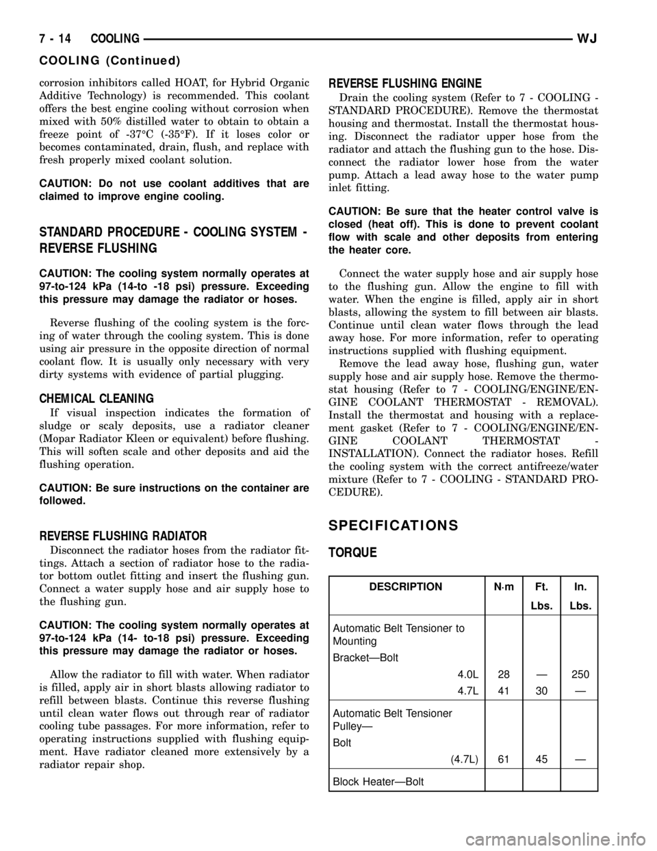
TORQUE
DESCRIPTION N´m Ft. In.
Lbs. Lbs.
Automatic Belt Tensioner to
Mounting
BracketÐBolt
4.0L 28 Ð 250
4.7L 41 30 Ð
Automatic Belt Tensioner
PulleyÐ
Bolt
(4.7L) 61 45 Ð
Block HeaterÐBolt
7 - 14 COOLINGWJ
COOLING (Continued)