Trim JEEP GRAND CHEROKEE 2002 WJ / 2.G Workshop Manual
[x] Cancel search | Manufacturer: JEEP, Model Year: 2002, Model line: GRAND CHEROKEE, Model: JEEP GRAND CHEROKEE 2002 WJ / 2.GPages: 2199, PDF Size: 76.01 MB
Page 1882 of 2199

LIFTGATE
REMOVAL
CAUTION: DO NOT DISCONNECT THE SUPPORT ROD
CYLINDERS WITH THE LIFTGATE CLOSED. THE SUP-
PORT ROD PISTONS ARE OPERATED BY HIGH PRES-
SURE GAS. THIS PRESSURE COULD CAUSE DAMAGE
AND /OR PERSONAL INJURY IF THEY ARE REMOVED
WHILE THE PISTONS ARE COMPRESSED.
(1) Open the liftgate. Support the liftgate for ease
of repair.
(2) Remove the liftgate trim panel.
(3) Remove the prop rods from the liftgate.
(4) Unplug the wire harnesses and disconnect the
washer hose.
(5) Mark the hinge location with a wax pencil or
other suitable device (Fig. 5).
(6) Remove the hinge screws and remove liftgate
from vehicle.
INSTALLATION
(1) Position the liftgate on the vehicle and align
the witness marks.
(2) Install the hinge screws at liftgate. Tighten
hinge screws to 28N´m (21ft. lbs.).
(3) Connect the wire harnesses and the washer
hose.
(4) Install the trim panel.
(5) Install the prop rods.
(6) Close the liftgate and check for proper latching
and alignment.
ADJUSTMENTS
LIFTGATE ADJUSTMENT
The position of the liftgate can be adjusted upward
or downward by the use of slots in the hinge. An
inward or outward adjustment is achieved by use of
slots in the body. If an inward or outward adjustment
is needed, use 3MŸ Fast and Firm or equivalent on
the hinge to body mating surface as a sealant.
TRIM PANEL
REMOVAL
REMOVAL - LIFTGATE TRIM PANEL
NOTE: The liftgate trim panel is attached with
screws and spring clips.
(1) Raise the liftgate.
(2) Remove the screws securing the liftgate trim
panel to the liftgate (Fig. 6).
(3) Disconnect the rear window defroster wires.
(4) Using a trim stick, or other suitable tool, pry
the liftgate trim panel off the liftgate.
Fig. 5 Liftgate
1 - HINGE
2 - LIFTGATE
Fig. 6 Liftgate Trim Panel
1 - LIFTGATE
2 - LIFTGATE TRIM PANEL
WJDECKLID/HATCH/LIFTGATE/TAILGATE 23 - 9
Page 1883 of 2199

REMOVAL - LOWER LIFTGATE OPENING TRIM
PANEL
(1) Remove screws at outboard end of lower lift-
gate trim panel.
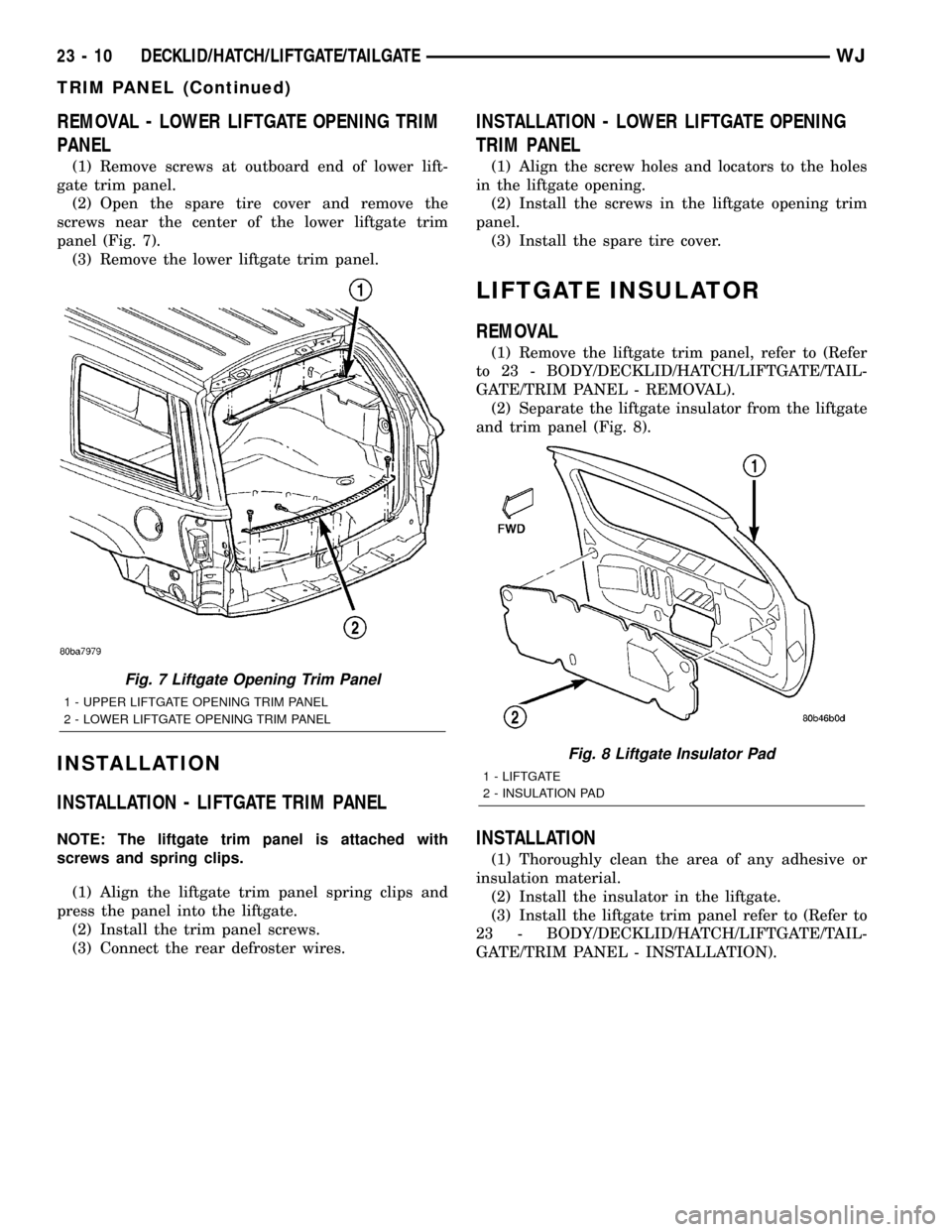
(2) Open the spare tire cover and remove the
screws near the center of the lower liftgate trim
panel (Fig. 7).
(3) Remove the lower liftgate trim panel.
INSTALLATION
INSTALLATION - LIFTGATE TRIM PANEL
NOTE: The liftgate trim panel is attached with
screws and spring clips.
(1) Align the liftgate trim panel spring clips and
press the panel into the liftgate.
(2) Install the trim panel screws.
(3) Connect the rear defroster wires.
INSTALLATION - LOWER LIFTGATE OPENING
TRIM PANEL
(1) Align the screw holes and locators to the holes
in the liftgate opening.
(2) Install the screws in the liftgate opening trim
panel.
(3) Install the spare tire cover.
LIFTGATE INSULATOR
REMOVAL
(1) Remove the liftgate trim panel, refer to (Refer
to 23 - BODY/DECKLID/HATCH/LIFTGATE/TAIL-
GATE/TRIM PANEL - REMOVAL).
(2) Separate the liftgate insulator from the liftgate
and trim panel (Fig. 8).
INSTALLATION
(1) Thoroughly clean the area of any adhesive or
insulation material.
(2) Install the insulator in the liftgate.
(3) Install the liftgate trim panel refer to (Refer to
23 - BODY/DECKLID/HATCH/LIFTGATE/TAIL-
GATE/TRIM PANEL - INSTALLATION).
Fig. 7 Liftgate Opening Trim Panel
1 - UPPER LIFTGATE OPENING TRIM PANEL
2 - LOWER LIFTGATE OPENING TRIM PANEL
Fig. 8 Liftgate Insulator Pad
1 - LIFTGATE
2 - INSULATION PAD
23 - 10 DECKLID/HATCH/LIFTGATE/TAILGATEWJ
TRIM PANEL (Continued)
Page 1884 of 2199

DOOR - FRONT
TABLE OF CONTENTS
page page
CHECK STRAP
REMOVAL.............................11
INSTALLATION.........................11
DOOR
REMOVAL.............................12
INSTALLATION.........................12
ADJUSTMENTS
DOOR ADJUSTMENT..................12
DOOR GLASS
REMOVAL.............................12
INSTALLATION.........................12
EXTERIOR HANDLE
REMOVAL.............................13
INSTALLATION.........................13
GLASS RUN CHANNEL
REMOVAL.............................13
INSTALLATION.........................14
HINGE
REMOVAL.............................14
INSTALLATION.........................15
INSIDE HANDLE ACTUATOR
REMOVAL.............................15INSTALLATION.........................15
LATCH
REMOVAL.............................15
INSTALLATION.........................15
ADJUSTMENTS
DOOR LATCH........................16
LATCH STRIKER
REMOVAL.............................16
INSTALLATION.........................16
LOCK CYLINDER
REMOVAL.............................16
INSTALLATION.........................17
TRIM PANEL
REMOVAL.............................17
INSTALLATION.........................17
WATERDAM
REMOVAL.............................17
INSTALLATION.........................17
WINDOW REGULATOR
REMOVAL.............................18
INSTALLATION.........................18
CHECK STRAP
REMOVAL
(1) Remove the waterdam, refer to (Refer to 23 -
BODY/DOOR - FRONT/WATERDAM - REMOVAL).
(2) Remove speaker.
(3) Remove screws attaching door check to A-pillar.
(4) Remove nuts attaching door check to door (Fig.
1).
(5) Remove door check through speaker location
hole.
INSTALLATION
(1) Position door check on door through speaker
location hole (Fig. 1).
(2) Install nuts attaching door check to door.
(3) Install screws attaching door check to A-pillar.
(4) Install speaker.
(5) Install the waterdam, refer to (Refer to 23 -
BODY/DOOR - FRONT/WATERDAM - INSTALLA-
TION).
Fig. 1 Door Check
1 - DOOR CHECK
2 - FRONT DOOR
WJDOOR - FRONT 23 - 11
Page 1888 of 2199

INSTALLATION
(1) Position hinge on ªAº pillar. (Use 3MtFast and
Firm or equivalent on the hinge to body mating sur-
face as a sealant.)
(2) Install hinge to body bolts, but do not tighten.
(3) Align the hinge to the reference marks and
torque the bolts to 35N´m (26 ft. lbs.).
(4) Install the door on the hinge and align with the
reference marks.
(5) Tighten the door to hinge fasteners.
(6) For adjustment see door adjustment procedure.
INSIDE HANDLE ACTUATOR
REMOVAL
(1) Remove door trim panel, refer to (Refer to 23 -
BODY/DOOR - FRONT/TRIM PANEL - REMOVAL).
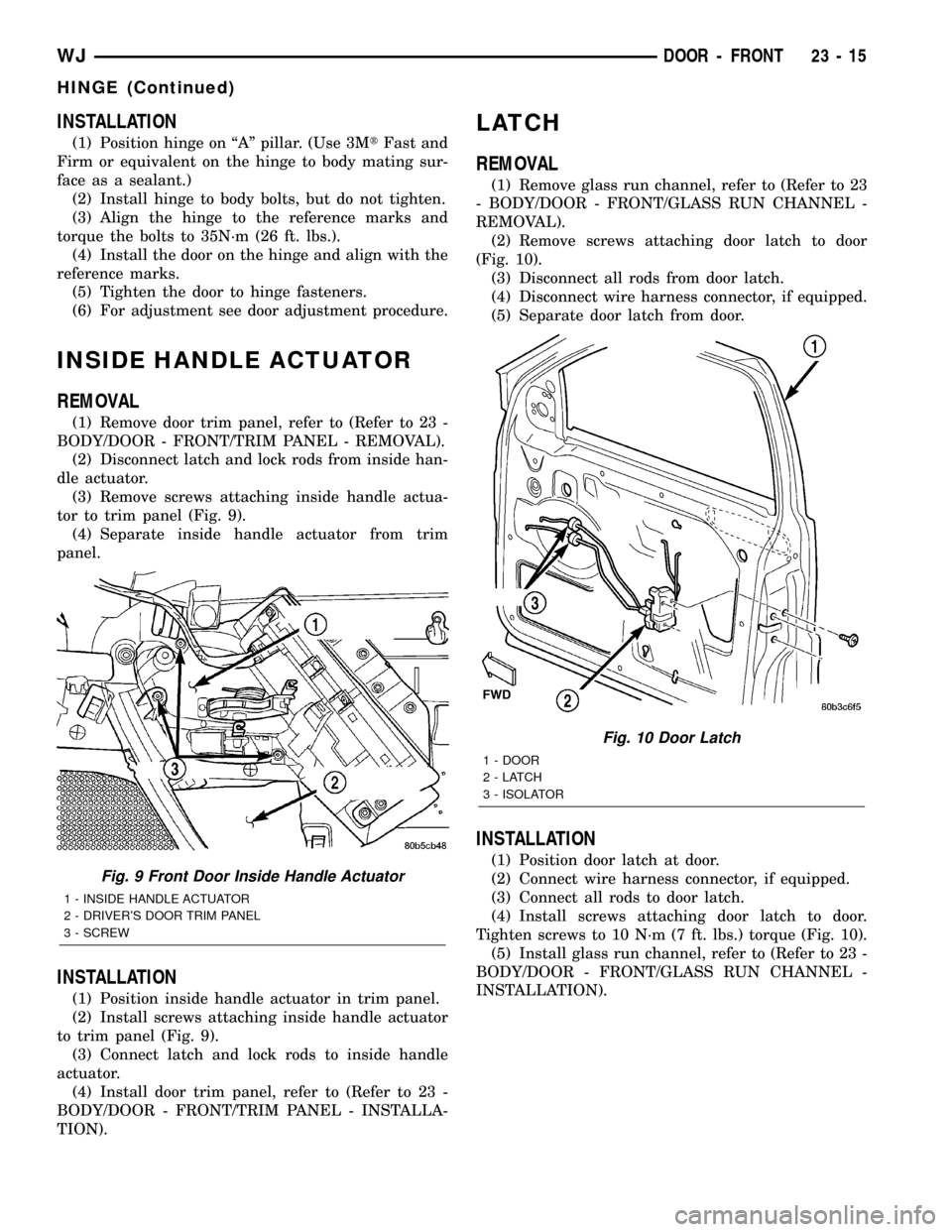
(2) Disconnect latch and lock rods from inside han-
dle actuator.
(3) Remove screws attaching inside handle actua-
tor to trim panel (Fig. 9).
(4) Separate inside handle actuator from trim
panel.
INSTALLATION
(1) Position inside handle actuator in trim panel.
(2) Install screws attaching inside handle actuator
to trim panel (Fig. 9).
(3) Connect latch and lock rods to inside handle
actuator.
(4) Install door trim panel, refer to (Refer to 23 -
BODY/DOOR - FRONT/TRIM PANEL - INSTALLA-
TION).
LATCH
REMOVAL
(1) Remove glass run channel, refer to (Refer to 23
- BODY/DOOR - FRONT/GLASS RUN CHANNEL -
REMOVAL).
(2) Remove screws attaching door latch to door
(Fig. 10).
(3) Disconnect all rods from door latch.
(4) Disconnect wire harness connector, if equipped.
(5) Separate door latch from door.
INSTALLATION
(1) Position door latch at door.
(2) Connect wire harness connector, if equipped.
(3) Connect all rods to door latch.
(4) Install screws attaching door latch to door.
Tighten screws to 10 N´m (7 ft. lbs.) torque (Fig. 10).
(5) Install glass run channel, refer to (Refer to 23 -
BODY/DOOR - FRONT/GLASS RUN CHANNEL -
INSTALLATION).
Fig. 9 Front Door Inside Handle Actuator
1 - INSIDE HANDLE ACTUATOR
2 - DRIVER'S DOOR TRIM PANEL
3 - SCREW
Fig. 10 Door Latch
1 - DOOR
2-LATCH
3 - ISOLATOR
WJDOOR - FRONT 23 - 15
HINGE (Continued)
Page 1890 of 2199

INSTALLATION
(1) Connect lock cylinder switch, if equipped.
(2) Position lock cylinder in door handle.
(3) Position lock cylinder retainer and install
screw (Fig. 13).
(4) Install outside door handle, refer to (Refer to
23 - BODY/DOOR - FRONT/EXTERIOR HANDLE -
INSTALLATION).
TRIM PANEL
REMOVAL
(1) Remove trim plug from mirror flag bezel.
(2) Remove screws attaching trim panel to door
(Fig. 14).
(3) Using trim remover (C-4829 or equivalent),
detach trim panel perimeter push-in fasteners from
door inner panel.
(4) Lift trim panel upward and separate from door.
(5) If equipped, disconnect harness connectors for
power accessories.
(6) Disconnect latch rods from inside handle actua-
tor.
(7) Separate trim panel from vehicle.
INSTALLATION
(1) Connect latch rods to inside handle actuator.
(2) If equipped, connect harness connectors to
power accessories.
(3) Position trim panel on door inner panel.
(4) Press trim panel push-in fasteners inward
around perimeter of door.
(5) Install screws attaching trim panel to door
(Fig. 14).
(6) Install trim plug in mirror flag bezel.
WATERDAM
REMOVAL
(1) Remove door trim panel, refer to (Refer to 23 -
BODY/DOOR - FRONT/TRIM PANEL - REMOVAL).
(2) Peel the waterdam from door.
(3) Route all harnesses and linkage rods through
waterdam as necessary.
(4) Separate waterdam from door (Fig. 15).
INSTALLATION
(1) Waterdam contact surface must be free of con-
taminants. Clean as necessary.
(2) Route all harnesses and linkage rods through
waterdam as necessary.
(3) Position waterdam on door and align all holes.
(4) Press waterdam on door (Fig. 15).
(5) Install door trim panel, refer to (Refer to 23 -
BODY/DOOR - FRONT/TRIM PANEL - INSTALLA-
TION).Fig. 14 Front Door Trim Panel
1 - HARNESS CONNECTOR
2 - NUTSERT
3 - TRIM PLUG
4 - TRIM PANEL
5 - PUSH-IN FASTENER
6 - HARNESS CONNECTOR
7 - LATCH RODS
Fig. 15 Front Door Waterdam
1 - INSULATOR PAD
WJDOOR - FRONT 23 - 17
LOCK CYLINDER (Continued)
Page 1892 of 2199

DOORS - REAR
TABLE OF CONTENTS
page page
CHECK STRAP
REMOVAL.............................19
INSTALLATION.........................19
DOOR
REMOVAL.............................20
INSTALLATION.........................20
DOOR GLASS
REMOVAL.............................20
INSTALLATION.........................20
EXTERIOR HANDLE
REMOVAL.............................20
INSTALLATION.........................21
HINGE
REMOVAL.............................21
INSTALLATION.........................21
INSIDE HANDLE ACTUATOR
REMOVAL.............................22INSTALLATION.........................22
LATCH
REMOVAL.............................22
INSTALLATION.........................22
LATCH STRIKER
REMOVAL.............................23
INSTALLATION.........................23
TRIM PANEL
REMOVAL.............................23
INSTALLATION.........................23
WATERDAM
REMOVAL.............................23
INSTALLATION.........................24
WINDOW REGULATOR
REMOVAL.............................24
INSTALLATION.........................24
CHECK STRAP
REMOVAL
(1) Remove waterdam, refer to (Refer to 23 -
BODY/DOORS - REAR/WATERDAM - REMOVAL).
(2) Remove speaker.
(3) Remove screws attaching door check to B-pillar.
(4) Remove nuts attaching door check to door (Fig.
1).
(5) Remove door check through speaker location
hole.
INSTALLATION
(1) Position door check on door through speaker
location hole.
(2) Install nuts attaching door check to door (Fig.
1).
(3) Install screws attaching door check to B-pillar.
(4) Install speaker.
(5) Install waterdam, refer to (Refer to 23 - BODY/
DOORS - REAR/WATERDAM - INSTALLATION).
Fig. 1 Door Check
1 - DOOR CHECK
2 - REAR DOOR
WJDOORS - REAR 23 - 19
Page 1894 of 2199

INSTALLATION
(1) Position outside handle in door.
(2) Install fasteners attaching outside handle to
door (Fig. 4).
(3) Connect outside handle to latch rod.
(4) Connect lock knob to latch rod.
(5) Locate glass to full down position.
(6) Install waterdam, refer to (Refer to 23 - BODY/
DOORS - REAR/WATERDAM - INSTALLATION).
HINGE
REMOVAL
(1) Open front door and rear door.
(2) Reference mark hinges for installation (Fig. 5).
(3) Support rear door for removal of hinges.
(4) Remove B pillar trim.
(5) Remove nuts holding door to hinge.
(6) Remove door.
(7) Remove bolts holding hinge to B pillar.
INSTALLATION
(1) Install hinge on B pillar and align reference
marks (Fig. 5).
(2) Install bolts holding hinge to B pillar. Tighten
bolts to 35N´m (23 ft. lbs.).
(3) Install door on hinge and align reference
marks. Install bolts and tighten to 35N´m (26 ft.
lbs.).
(4) Check door for fit and ease of operation. Adjust
as necessary, refer to (Refer to 23 - BODY/DOOR -
FRONT/DOOR - ADJUSTMENTS).
(5) Install B pillar trim.
Fig. 4 Front
1 - DOOR
2 - OUTSIDE HANDLE
Fig. 5 Rear Door Hinge
1 - UPPER HINGE
2 - WASHER
3 - WASHER
4 - LOWER HINGE
5 - REAR DOOR
WJDOORS - REAR 23 - 21
EXTERIOR HANDLE (Continued)
Page 1895 of 2199

INSIDE HANDLE ACTUATOR
REMOVAL
(1) Remove door trim panel, refer to (Refer to 23 -
BODY/DOORS - REAR/TRIM PANEL - REMOVAL).
(2) Disconnect latch and lock rods from inside han-
dle actuator.
(3) Remove screws attaching inside handle actua-
tor to trim panel (Fig. 6).
(4) Separate inside handle actuator from trim
panel.
INSTALLATION
(1) Position inside handle actuator in trim panel.
(2) Install screws attaching inside handle actuator
to trim panel (Fig. 6).
(3) Connect latch and lock rods to inside handle
actuator.
(4) Install door trim panel, refer to (Refer to 23 -
BODY/DOORS - REAR/TRIM PANEL - INSTALLA-
TION).
LATCH
REMOVAL
(1) Remove waterdam, refer to (Refer to 23 -
BODY/DOORS - REAR/WATERDAM - REMOVAL).
(2) Remove screws attaching latch to door (Fig. 7).
(3) Disconnect rods from door latch.
(4) Separate door latch from door.
INSTALLATION
(1) position latch in door.
(2) Connect rods to door latch.
(3) Install screws attaching latch to door. Tighten
screws to 10 N´m (95 in. lbs.) torque (Fig. 7).
(4) Install waterdam, refer to (Refer to 23 - BODY/
DOORS - REAR/WATERDAM - INSTALLATION).
Fig. 6 Rear Door Inside Handle Actuator
1 - REAR DOOR TRIM PANEL
2 - SCREW
3 - INSIDE HANDLE ACTUATOR
Fig. 7 Rear Door Latch
1 - DOOR
2-LATCH
3 - OUTSIDE HANDLE
23 - 22 DOORS - REARWJ
Page 1896 of 2199

LATCH STRIKER
REMOVAL
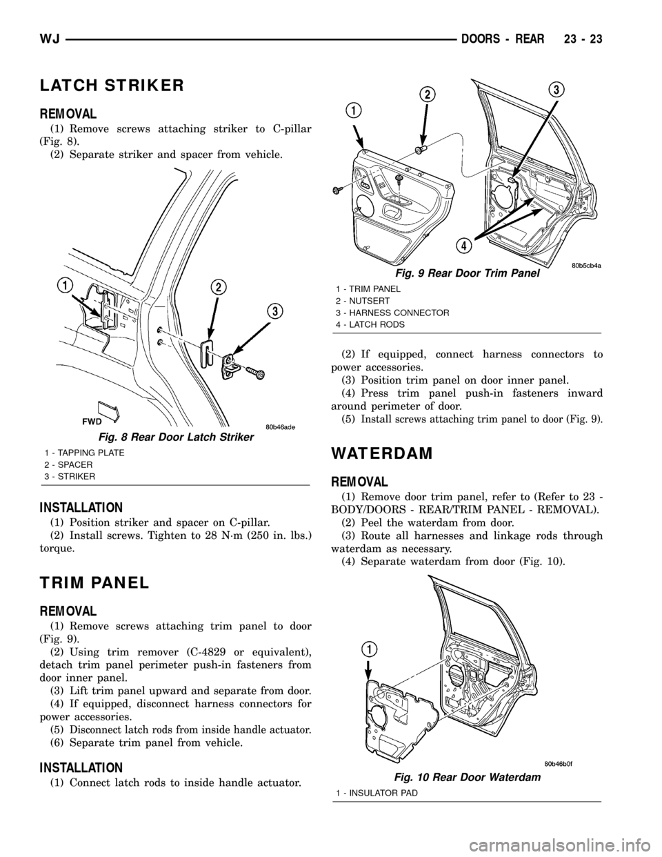
(1) Remove screws attaching striker to C-pillar
(Fig. 8).
(2) Separate striker and spacer from vehicle.
INSTALLATION
(1) Position striker and spacer on C-pillar.
(2) Install screws. Tighten to 28 N´m (250 in. lbs.)
torque.
TRIM PANEL
REMOVAL
(1) Remove screws attaching trim panel to door
(Fig. 9).
(2) Using trim remover (C-4829 or equivalent),
detach trim panel perimeter push-in fasteners from
door inner panel.
(3) Lift trim panel upward and separate from door.
(4) If equipped, disconnect harness connectors for
power accessories.
(5)
Disconnect latch rods from inside handle actuator.
(6) Separate trim panel from vehicle.
INSTALLATION
(1) Connect latch rods to inside handle actuator.(2) If equipped, connect harness connectors to
power accessories.
(3) Position trim panel on door inner panel.
(4) Press trim panel push-in fasteners inward
around perimeter of door.
(5)
Install screws attaching trim panel to door (Fig. 9).
WATERDAM
REMOVAL
(1) Remove door trim panel, refer to (Refer to 23 -
BODY/DOORS - REAR/TRIM PANEL - REMOVAL).
(2) Peel the waterdam from door.
(3) Route all harnesses and linkage rods through
waterdam as necessary.
(4) Separate waterdam from door (Fig. 10).
Fig. 8 Rear Door Latch Striker
1 - TAPPING PLATE
2 - SPACER
3 - STRIKER
Fig. 9 Rear Door Trim Panel
1 - TRIM PANEL
2 - NUTSERT
3 - HARNESS CONNECTOR
4 - LATCH RODS
Fig. 10 Rear Door Waterdam
1 - INSULATOR PAD
WJDOORS - REAR 23 - 23
Page 1897 of 2199

INSTALLATION
(1) Waterdam contact surface must be free of con-
taminants. Clean as necessary.
(2) Route all harnesses and linkage rods through
waterdam as necessary.
(3) Position waterdam on door and align all holes
(Fig. 10).
(4) Press waterdam on door.
(5) Install door trim panel, refer to (Refer to 23 -
BODY/DOORS - REAR/TRIM PANEL - INSTALLA-
TION).
WINDOW REGULATOR
REMOVAL
(1) Remove waterdam, refer to (Refer to 23 -
BODY/DOORS - REAR/WATERDAM - REMOVAL).
(2) Remove the stationary glass, refer to (Refer to
23 - BODY/STATIONARY GLASS/DOOR GLASS -
REMOVAL).
(3) Raise the door glass and support.
(4) Disconnect the speaker harness and power win-
dow harness, if equipped.
(5) Remove the window clips retaining regulator
(Fig. 11).
(6) Remove the door glass.
(7) Remove the fasteners retaining the regulator
(Fig. 12).
(8) Remove the regulator.
INSTALLATION
(1) Position the window regulator in the door.
(2) Install the fasteners retaining the regulator
(Fig. 12).
(3) Install the door glass.
(4) Install the window clips retaining regulator
(Fig. 11).
(5) Lower the door glass.
(6) Install the stationary glass, refer to (Refer to
23 - BODY/STATIONARY GLASS/DOOR GLASS -
INSTALLATION).
(7) Connect the power window and speaker har-
ness if equipped.
(8) Install the waterdam, refer to (Refer to 23 -
BODY/DOORS - REAR/WATERDAM - INSTALLA-
TION).
(9) Cycle the glass and check for proper operation.
Fig. 11 Window Regulator Retainer Clips
1 - GLASS
2 - RETAINER
3 - CLIP
4 - LIFT PLATE
5 - REGULATOR
6 - CLIP
Fig. 12 Rear Door Window Regulator
1 - DOOR
2 - REGULATOR
23 - 24 DOORS - REARWJ
WATERDAM (Continued)