Lamps JEEP GRAND CHEROKEE 2002 WJ / 2.G Workshop Manual
[x] Cancel search | Manufacturer: JEEP, Model Year: 2002, Model line: GRAND CHEROKEE, Model: JEEP GRAND CHEROKEE 2002 WJ / 2.GPages: 2199, PDF Size: 76.01 MB
Page 606 of 2199

cluster circuitry that controls the lamp, (Refer to 8 -
ELECTRICAL/INSTRUMENT CLUSTER - DIAGNO-
SIS AND TESTING). If the instrument cluster turns
on the SKIS indicator lamp after the bulb test, either
solid or flashing, it indicates that a SKIS malfunction
has occurred or that the SKIS is inoperative. For
proper diagnosis of the SKIS, the PCI data bus, or
the message inputs to the instrument cluster that
control the SKIS indicator lamp, a DRBIIItscan tool
and the appropriate diagnostic information are
required.
TRANSPONDER KEY
DESCRIPTION
Each ignition key used in the Sentry Key Immobi-
lizer System (SKIS) has an integral transponder chip
(Fig. 10). Ignition keys with this feature can be
readily identified by a gray rubber cap molded onto
the head of the key, while conventional ignition keys
have a black molded rubber cap. The transponder
chip is concealed beneath the molded rubber cap,
where it is molded into the head of the metal key.
Each new Sentry Key has a unique transponder iden-
tification code permanently programmed into it by
the manufacturer. The Sentry Key transponder if
faulty or damaged, must be replaced.
OPERATION
When the ignition switch is turned to the On posi-
tion, the Sentry Key Immobilizer Module (SKIM)communicates through its antenna with the Sentry
Key transponder using a Radio Frequency (RF) sig-
nal. The SKIM then waits for a RF response from the
transponder through the same antenna. The Sentry
Key transponder chip is within the range of the
SKIM transceiver antenna ring when it is inserted
into the ignition lock cylinder. The SKIM determines
whether a valid key is present in the ignition lock
cylinder based upon the response from the transpon-
der. If a valid key is detected, that fact is communi-
cated by the SKIM to the Powertrain Control Module
(PCM) over the Programmable Communications
Interface (PCI) data bus, and the PCM allows the
engine to continue running. If the PCM receives an
invalid key message, or receives no message from the
SKIM over the PCI data bus, the engine will be dis-
abled after about two seconds of operation. The Elec-
troMechanical Instrument Cluster (EMIC) will also
respond to the invalid key message on the PCI data
bus by flashing the SKIS indicator on and off.
Each Sentry Key has a unique transponder identi-
fication code permanently programmed into it by the
manufacturer. Likewise, the SKIM has a unique
Secret Key code programmed into it by the manufac-
turer. When a Sentry Key is programmed into the
memory of the SKIM, the SKIM stores the transpon-
der identification code from the Sentry Key, and the
Sentry Key learns the Secret Key code from the
SKIM. Once the Sentry Key learns the Secret Key
code of the SKIM, it is permanently stored in the
memory of the transponder. Therefore, once a Sentry
Key has been programmed to a particular vehicle, it
cannot be used on any other vehicle. (Refer to 8 -
ELECTRICAL/VEHICLE THEFT SECURITY -
STANDARD PROCEDURE - TRANSPONDER PRO-
GRAMMING).
VTSS INDICATOR
DESCRIPTION
The Vehicle Theft Security System (VTSS) indica-
tor consists of a red Light-Emitting Diode that is
mounted and integral to the automatic headlamp
light sensor photo diode unit, which is located on the
top of the instrument panel. The remainder of the
housing including the mount and the electrical con-
nection are concealed beneath the instrument panel
top cover.
The VTSS indicator cannot be adjusted or repaired
the entire automatic headlamp light sensor/VTSS
indicator must be replaced. (Refer to 8 - ELECTRI-
CAL/LAMPS/LIGHTING - EXTERIOR/AUTO HEAD-
LAMP SENSOR - REMOVAL).
Fig. 10 Sentry Key Immobilizer Transponder
1 - MOLDED CAP
2 - TRANSPONDER CHIP
3 - MOLDED CAP REMOVED
4 - TRANSPONDER KEY
WJVEHICLE THEFT SECURITY 8Q - 15
SKIS INDICATOR LAMP (Continued)
Page 611 of 2199

operates the front wipers at the programmed speed
and intervals requested by the RSM to maintain vis-
ibility through the windshield.
²Continuous Wipe Mode- The control knob on
the control stalk of the right (wiper) multi-function
switch has two continuous wipe positions, Low and
High. When selected, these switch positions will
cause the two-speed front wiper motor to operate in a
continuous low or high speed cycle.
²Headlamps On With Wipers- The BCM pro-
vides an automatic headlamps on with wipers feature
for models equipped with the optional automatic
headlamps. This is a customer programmable fea-
ture. If this feature is enabled, the headlamps will
turn on automatically when the windshield wipers
are turned on; and, if the headlamps were turned on
automatically when the wipers were turned on, they
will turn off automatically when the wipers are
turned off. In models equipped with the optional
automatic wiper feature, when the automatic wiper
mode is selected the headlamps will turn on auto-
matically only after the wipers complete three auto-
matic wipe cycles within about thirty seconds, and
they will turn off automatically after three minutes
elapse without any automatic wipe cycles. (Refer to 8
- ELECTRICAL/OVERHEAD CONSOLE - STAN-
DARD PROCEDURE - ELECTRONIC VEHICLE
INFORMATION CENTER PROGRAMMING).
²Mist Wipe Mode- The control stalk of the right
(wiper) multi-function switch has a momentary Mist
position. When selected, this switch position will
operate the front wipers in a low speed continuous
cycle for as long as the switch is held closed, then
will complete the current wipe cycle and park the
front wiper blades near the base of the windshield
when the switch is released.
²Speed Sensitive Intermittent Wipe Mode-
Except on models equipped with the optional auto-
matic wiper system, the internal circuitry of both the
right (wiper) multi-function switch and the BCM
work in concert to provide an intermittent wipe mode
with five delay interval selections. The BCM auto-
matically adjusts each manually selected delay inter-
val to compensate for vehicle speed.
²Washer Mode- When the momentary front
wash position of the control stalk for the right
(wiper) multi-function switch is selected with the
front wiper system operating in a continuous wipe
mode, washer fluid will be dispensed onto the wind-
shield glass through the washer nozzles for as long
as the washer switch is held closed. When the front
washer switch is actuated with the front wiper sys-
tem operating in an intermittent wipe mode, washer
fluid is still dispensed until the switch is released;
however, the front wipers will operate in a low speed
continuous cycle from the time the washer switch isclosed until several wipe cycles after the switch is
released, before returning to the selected intermit-
tent wipe mode.
²Wipe-After-Wash Mode- When the momentary
front wash position of the control stalk for the right
(wiper) multi-function switch is selected with the
front wiper system turned Off, the internal circuitry
of the BCM provides a wipe-after-wash feature.
When selected, this feature will operate the front
washer pump/motor and the front wipers for as long
as the front washer switch is held closed, then pro-
vide several additional wipe cycles after the switch is
released before parking the front wiper blades near
the base of the windshield.
OPERATION
The front wiper and washer system is designed to
provide the vehicle operator with a convenient, safe,
and reliable means of maintaining visibility through
the windshield glass. The various components of this
system are designed to convert electrical energy pro-
duced by the vehicle electrical system into the
mechanical action of the wiper blades to wipe the
outside surface of the glass, as well as into the
hydraulic action of the washer system to apply
washer fluid stored in an on-board reservoir to the
area of the glass to be wiped. When combined, these
components provide the means to effectively main-
tain clear visibility for the vehicle operator by remov-
ing excess accumulations of rain, snow, bugs, mud, or
other minor debris that might be encountered while
driving the vehicle under numerous types of inclem-
ent operating conditions from the outside windshield
glass surface.
The vehicle operator initiates all front wiper and
washer system functions with the control stalk of the
right (wiper) multi-function switch that extends from
the right side of the steering column, just below the
steering wheel. Rotating the control knob on the end
of the right (wiper) multi-function switch control
stalk selects the Off, Delay (on models not equipped
with the optional automatic wiper system), Auto (on
models equipped with the optional automatic wiper
system), Low, or High front wiper system operating
modes. In the Delay mode, the control knob also
allows the vehicle operator to select from one of five
intermittent wipe Delay intervals. In the Auto mode,
the control knob also allows the vehicle operator to
select from one of five automatic wiper sensitivity
levels. Pulling the right control stalk downwards
actuates the momentary front wiper system Mist
mode switch, while pulling the right control stalk
towards the steering wheel actuates the front washer
system switch. The multi-function switch provides
hard wired resistor multiplexed inputs to the Body
Control Module (BCM) for all of the front wiper sys-
8R - 4 FRONT WIPERS/WASHERSWJ
FRONT WIPERS/WASHERS (Continued)
Page 642 of 2199

stalk is moved to the rear Wash position, the Wash
position circuitry within the switch directs battery
current to the rear washer pump/motor unit, and to
both the rear wiper motor control and rear washer
switch output signal inputs of the rear wiper module
electronic circuitry, which causes the wiper motor to
run at a fixed cycle for as long as the Wash mode is
selected plus about three additional fixed wipe cycles.
The rear wiper module electronic circuitry controls
the switching of battery current to the rear wiper
motor brush, which controls wiper motor operation.
The intermittent wipe and wipe-after-wash features
of the rear wiper and washer system are both pro-
vided by the rear wiper module electronic circuitry.
The rear wiper module electronic circuitry also mon-
itors the liftgate flip-up glass ajar switch and will
park the rear wiper blade off of the glass any time it
senses that the liftgate flip-up glass is ajar, the igni-
tion switch is turned to the Off position, or the right
multi-function switch control sleeve is moved to the
Off position. This feature ensures that the rear wiper
blade will not interfere with or be damaged by the
operation of the liftgate flip-up glass. However, if the
ignition switch is turned to the Off position or the
liftgate flip-up glass is opened while the rear wiper is
operating, the right multi-function switch control
sleeve must be cycled to the Off position and back to
the On or Delay position after the ignition switch is
turned back On or the liftgate flip-up glass is closed
before the rear wiper will operate again.
Refer to the owner's manual in the vehicle glove
box for more information on the features and opera-
tion of the rear wiper and washer system.
DIAGNOSIS AND TESTING - REAR WIPER &
WASHER SYSTEM
WIPER SYSTEM
The diagnosis found here addresses an electrically
inoperative rear wiper system. If the rear wiper
motor operates, but the wiper does not move on the
liftgate glass, replace the faulty rear wiper module. If
the wiper operates, but chatters, lifts, or does not
clear the glass, clean and inspect the wiper system
components as required. (Refer to 8 - ELECTRICAL/
REAR WIPERS/WASHERS - INSPECTION) and
(Refer to 8 - ELECTRICAL/REAR WIPERS/WASH-
ERS - CLEANING). Refer to the appropriate wiring
information. The wiring information includes wiring
diagrams, proper wire and connector repair proce-
dures, details of wire harness routing and retention,
connector pin-out information and location views for
the various wire harness connectors, splices and
grounds.WARNING: ON VEHICLES EQUIPPED WITH AIR-
BAGS, DISABLE THE AIRBAG SYSTEM BEFORE
ATTEMPTING ANY STEERING WHEEL, STEERING
COLUMN, OR INSTRUMENT PANEL COMPONENT
DIAGNOSIS OR SERVICE. DISCONNECT AND ISO-
LATE THE BATTERY NEGATIVE (GROUND) CABLE,
THEN WAIT TWO MINUTES FOR THE AIRBAG SYS-
TEM CAPACITOR TO DISCHARGE BEFORE PER-
FORMING FURTHER DIAGNOSIS OR SERVICE. THIS
IS THE ONLY SURE WAY TO DISABLE THE AIRBAG
SYSTEM. FAILURE TO TAKE THE PROPER PRE-
CAUTIONS COULD RESULT IN ACCIDENTAL AIR-
BAG DEPLOYMENT AND POSSIBLE PERSONAL
INJURY.
(1) Check that the interior lighting switch on the
control stalk of the left multi-function switch is not
in the dome lamp disable position. With all four
doors and the liftgate closed, open the liftgate flip-up
glass. The interior lamps should light. If not, depress
the cargo lamp lens to actuate the cargo lamp defeat
switch and the interior lamps should light. Close all
four doors, the liftgate and the liftgate flip-up glass.
Note whether the interior lamps remain lighted.
They should turn off after about thirty seconds. If
OK, go to Step 2. If not OK, go to Step 9.
(2) Check the fused B(+) fuse (Fuse8-15ampere)
in the Junction Block (JB). If OK, go to Step 3. If not
OK, repair the shorted circuit or component as
required and replace the faulty fuse.
(3) Check for battery voltage at the fused B(+) fuse
(Fuse8-15ampere) in the JB. If OK, go to Step 4. If
not OK, repair the open fused B(+) circuit between
the JB and the Power Distribution Center (PDC) as
required.
(4) Check the fused ignition switch output (run-
acc) fuse (Fuse 29 - 10 ampere) in the JB. If OK, go
to Step 5. If not OK, repair the shorted circuit or
component as required and replace the faulty fuse.
(5) Turn the ignition switch to the On position.
Check for battery voltage at the fused ignition switch
output (run-acc) fuse (Fuse 29 - 10 ampere) in the
JB. If OK, turn the ignition switch to the Off position
and go to Step 6. If not OK, repair the open fused
ignition switch output (run-acc) circuit between the
JB and the ignition switch as required.
(6) Disconnect and isolate the battery negative
cable. Disconnect the instrument panel wire harness
connector for the right multi-function switch from the
switch connector receptacle. Reconnect the battery
negative cable. Turn the ignition switch to the On
position. Check for battery voltage at the fused igni-
tion switch output (run-acc) circuit cavity of the
instrument panel wire harness connector for the
right multi-function switch. If OK, go to Step 7. If
not OK, repair the open fused ignition switch output
WJREAR WIPERS/WASHERS 8R - 35
REAR WIPERS/WASHERS (Continued)
Page 672 of 2199

8W-02 COMPONENT INDEX
Component Page
A/C Compressor Clutch................. 8W-42
A/C Pressure Transducer................ 8W-42
Accelerator Pedal Position Sensor......... 8W-30
Accessory Delay Relay.................. 8W-64
Adjustable Pedals..................... 8W-30
Airbags............................. 8W-43
Ambient Temperature Sensor............ 8W-45
Antennas............................ 8W-47
Ash Receiver Lamp.................... 8W-44
Auto Shut Down Relay................. 8W-30
Automatic Day/Night Mirror............. 8W-49
Automatic Headlamp Light Sensor/VTSS
LED.............................. 8W-39
Automatic Zone Control Module.......... 8W-42
Back-Up Lamp Relay................... 8W-51
Battery Temperature Sensor............. 8W-30
Battery............................. 8W-20
Blend Door Motor/Actuator.............. 8W-42
Blower Motor......................... 8W-42
Body Control Module................... 8W-45
Boost Pressure Sensor.................. 8W-30
Brake Lamp Switch.................... 8W-33
Camshaft Position Sensor............... 8W-30
Capacitors........................... 8W-30
Cargo Lamp.......................... 8W-44
Center High Mounted Stop Lamp......... 8W-51
Cigar Lighter......................... 8W-41
Circuit Breakers...................... 8W-12
Clockspring.................. 8W-33, 41, 43, 47
Coil On Plugs......................... 8W-30
Coil Rail............................. 8W-30
Combination Flasher................... 8W-52
Compact Disc Changer.................. 8W-47
Controller Antilock Brake............... 8W-35
Coolant Level Sensor................... 8W-45
Courtesy Lamps....................... 8W-44
Crankcase Heater..................... 8W-30
Crankshaft Position Sensor.............. 8W-30
Cylinder Lock Switches................. 8W-61
Data Link Connector................... 8W-18
Diagnostic Junction Port................ 8W-18
EGR Solenoid......................... 8W-30
Electric Brake........................ 8W-54
Electronic Speed Control Servo........... 8W-33
Engine Control Module................. 8W-30
Engine Coolant Temperature Sensor...... 8W-30
Engine Oil Pressure Sensor.............. 8W-30
Engine Starter Motor................... 8W-21
EVAP/Purge Solenoid................... 8W-30
Fog Lamps........................ 8W-50, 51
Fuel Injectors......................... 8W-30
Fuel Pressure Sensor................... 8W-30Component Page
Fuel Pressure Solenoid................. 8W-30
Fuel Pump........................... 8W-30
Fuel Tank Module..................... 8W-30
Fuses............................ 8W-10, 12
Fusible Link....................... 8W-10, 20
Grounds............................. 8W-15
Generator......................... 8W-20, 30
Glove Box Lamp...................... 8W-44
Glow Plugs........................... 8W-30
Headlamp Leveling Motor............... 8W-50
Heated Seats......................... 8W-63
High Beam Headlamps................. 8W-50
Hood Ajar Switch...................... 8W-39
Horns............................... 8W-41
Hydraulic Cooling Module............ 8W-30, 42
Idle Air Control Motor.................. 8W-30
Ignition Switch....................... 8W-10
Impact Sensors....................... 8W-43
Input Speed Sensor.................... 8W-31
Instrument Cluster.................... 8W-40
Intake Air Temperature Sensor........... 8W-30
Intake Port Swirl Actuator.............. 8W-30
Intrusion Transceiver Module............ 8W-49
Junction Block........................ 8W-12
Knock Sensor......................... 8W-30
Lamp Assemblies................... 8W-51, 52
Leak Detection Pump.................. 8W-30
License Lamps........................ 8W-51
Liftgate............................. 8W-61
Line Pressure Sensor................... 8W-31
Low Beam Headlamps.................. 8W-50
Low Beam Relay...................... 8W-50
Low Beam/Daytime Running Lamp Relay . . . 8W-50
Lumbar Motor........................ 8W-63
Lumbar Switch....................... 8W-63
Manifold Absolute Pressure Sensor........ 8W-30
Manual Temperature Control............. 8W-42
Mass Air Flow Sensor.................. 8W-30
Memory Set Switch................. 8W-62, 63
Mode Door Motor/Actuator............... 8W-42
Multi-Function Switch............... 8W-50, 53
Output Speed Sensor................... 8W-31
Overhead Map/Courtesy Lamp........... 8W-44
Oxygen Sensors....................... 8W-30
Park Brake Switch..................... 8W-40
Park Lamp........................... 8W-50
Park/Neutral Position Switch............ 8W-31
Park/Turn Signal Lamps................ 8W-50
Power Amplifier....................... 8W-47
Power Connector...................... 8W-41
Power Distribution Center............... 8W-10
Power Mirrors........................ 8W-62
WJ8W-02 COMPONENT INDEX 8W - 02 - 1
Page 673 of 2199

Component Page
Power Outlet......................... 8W-41
Power Seats.......................... 8W-63
Power Windows....................... 8W-60
Powertrain Control Module.............. 8W-30
Radio............................... 8W-47
Rain Sensor.......................... 8W-49
Recirculation Door Motor/Actuator........ 8W-42
Red Brake Warning Indicator Switch....... 8W-35
Remote Keyless Module................. 8W-39
Remote Radio Switches................. 8W-47
Splices.............................. 8W-10
Seat Belt Switch...................... 8W-43
Seat Module.......................... 8W-63
Sentry Key Immobilizer Module.......... 8W-39
Shifter Assembly...................... 8W-31
Side Impact Sensors................... 8W-43
Side Marker Lamps.................... 8W-50
Side Repeater Lamps................... 8W-52
Siren............................... 8W-49
Speakers............................ 8W-47Component Page
Speed Control Switches................. 8W-33
Sunroof............................. 8W-64
Temperature Valve Actuator............. 8W-42
Throttle Position Sensor................ 8W-30
Trailer Tow.......................... 8W-54
Transfer Case Position Sensor............ 8W-31
Transmission......................... 8W-31
Turn Signal Lamps.................... 8W-52
Underhood Lamp...................... 8W-44
Vehicle Information Center.............. 8W-49
Viscous/Cabin Heater................... 8W-30
Visor/Vanity Lamps.................... 8W-44
Washer Fluid Level Switch.............. 8W-53
Wastegate Solenoid.................... 8W-30
Water In Fuel Sensor................... 8W-30
Wheel Speed Sensors................... 8W-35
Window Defogger...................... 8W-48
Wiper High/Low Relay.................. 8W-53
Wiper Motor.......................... 8W-53
Washer Pump......................... 8W-5
8W - 02 - 2 8W-02 COMPONENT INDEXWJ
Page 1056 of 2199
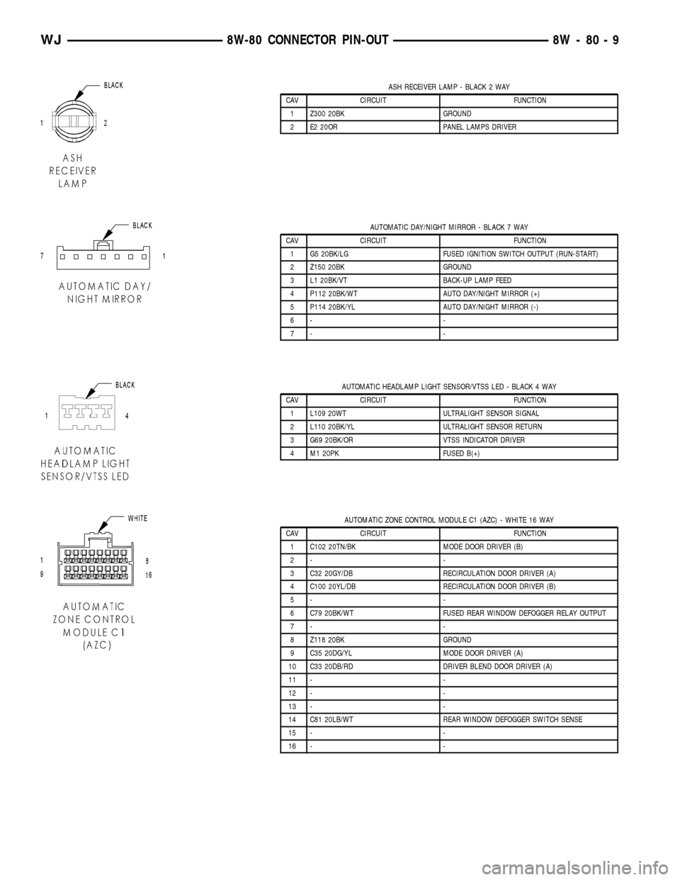
ASH RECEIVER LAMP - BLACK 2 WAY
CAV CIRCUIT FUNCTION
1 Z300 20BK GROUND
2 E2 20OR PANEL LAMPS DRIVER
AUTOMATIC DAY/NIGHT MIRROR - BLACK 7 WAY
CAV CIRCUIT FUNCTION
1 G5 20BK/LG FUSED IGNITION SWITCH OUTPUT (RUN-START)
2 Z150 20BK GROUND
3 L1 20BK/VT BACK-UP LAMP FEED
4 P112 20BK/WT AUTO DAY/NIGHT MIRROR (+)
5 P114 20BK/YL AUTO DAY/NIGHT MIRROR (-)
6- -
7- -
AUTOMATIC HEADLAMP LIGHT SENSOR/VTSS LED - BLACK 4 WAY
CAV CIRCUIT FUNCTION
1 L109 20WT ULTRALIGHT SENSOR SIGNAL
2 L110 20BK/YL ULTRALIGHT SENSOR RETURN
3 G69 20BK/OR VTSS INDICATOR DRIVER
4 M1 20PK FUSED B(+)
AUTOMATIC ZONE CONTROL MODULE C1 (AZC) - WHITE 16 WAY
CAV CIRCUIT FUNCTION
1 C102 20TN/BK MODE DOOR DRIVER (B)
2- -
3 C32 20GY/DB RECIRCULATION DOOR DRIVER (A)
4 C100 20YL/DB RECIRCULATION DOOR DRIVER (B)
5- -
6 C79 20BK/WT FUSED REAR WINDOW DEFOGGER RELAY OUTPUT
7- -
8 Z118 20BK GROUND
9 C35 20DG/YL MODE DOOR DRIVER (A)
10 C33 20DB/RD DRIVER BLEND DOOR DRIVER (A)
11 - -
12 - -
13 - -
14 C81 20LB/WT REAR WINDOW DEFOGGER SWITCH SENSE
15 - -
16 - -
WJ8W-80 CONNECTOR PIN-OUT 8W - 80 - 9
Page 1057 of 2199
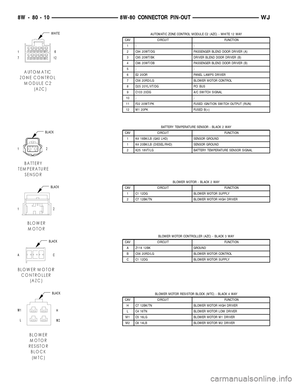
AUTOMATIC ZONE CONTROL MODULE C2 (AZC) - WHITE 12 WAY
CAV CIRCUIT FUNCTION
1- -
2 C94 20WT/DG PASSENGER BLEND DOOR DRIVER (A)
3 C95 20WT/BK DRIVER BLEND DOOR DRIVER (B)
4 C96 20WT/DB PASSENGER BLEND DOOR DRIVER (B)
5- -
6 E2 20OR PANEL LAMPS DRIVER
7 C56 20RD/LG BLOWER MOTOR CONTROL
8 D25 20YL/VT/DG PCI BUS
9 C103 20DG A/C SWITCH SIGNAL
10 - -
11 F22 20WT/PK FUSED IGNITION SWITCH OUTPUT (RUN)
12 M1 20PK FUSED B(+)
BATTERY TEMPERATURE SENSOR - BLACK 2 WAY
CAV CIRCUIT FUNCTION
1 K4 18BK/LB (GAS LHD) SENSOR GROUND
1 K4 20BK/LB (DIESEL/RHD) SENSOR GROUND
2 K25 18VT/LG BATTERY TEMPERATURE SENSOR SIGNAL
BLOWER MOTOR - BLACK 2 WAY
CAV CIRCUIT FUNCTION
1 C1 12DG BLOWER MOTOR SUPPLY
2 C7 12BK/TN BLOWER MOTOR HIGH DRIVER
BLOWER MOTOR CONTROLLER (AZC) - BLACK 3 WAY
CAV CIRCUIT FUNCTION
A Z118 12BK GROUND
B C56 20RD/LG BLOWER MOTOR CONTROL
C C1 12DG BLOWER MOTOR SUPPLY
BLOWER MOTOR RESISTOR BLOCK (MTC) - BLACK 4 WAY
CAV CIRCUIT FUNCTION
H C7 12BK/TN BLOWER MOTOR HIGH DRIVER
L C4 16TN BLOWER MOTOR LOW DRIVER
M1 C5 16LG BLOWER MOTOR M1 DRIVER
M2 C6 14LB BLOWER MOTOR M2 DRIVER
8W - 80 - 10 8W-80 CONNECTOR PIN-OUTWJ
Page 1058 of 2199
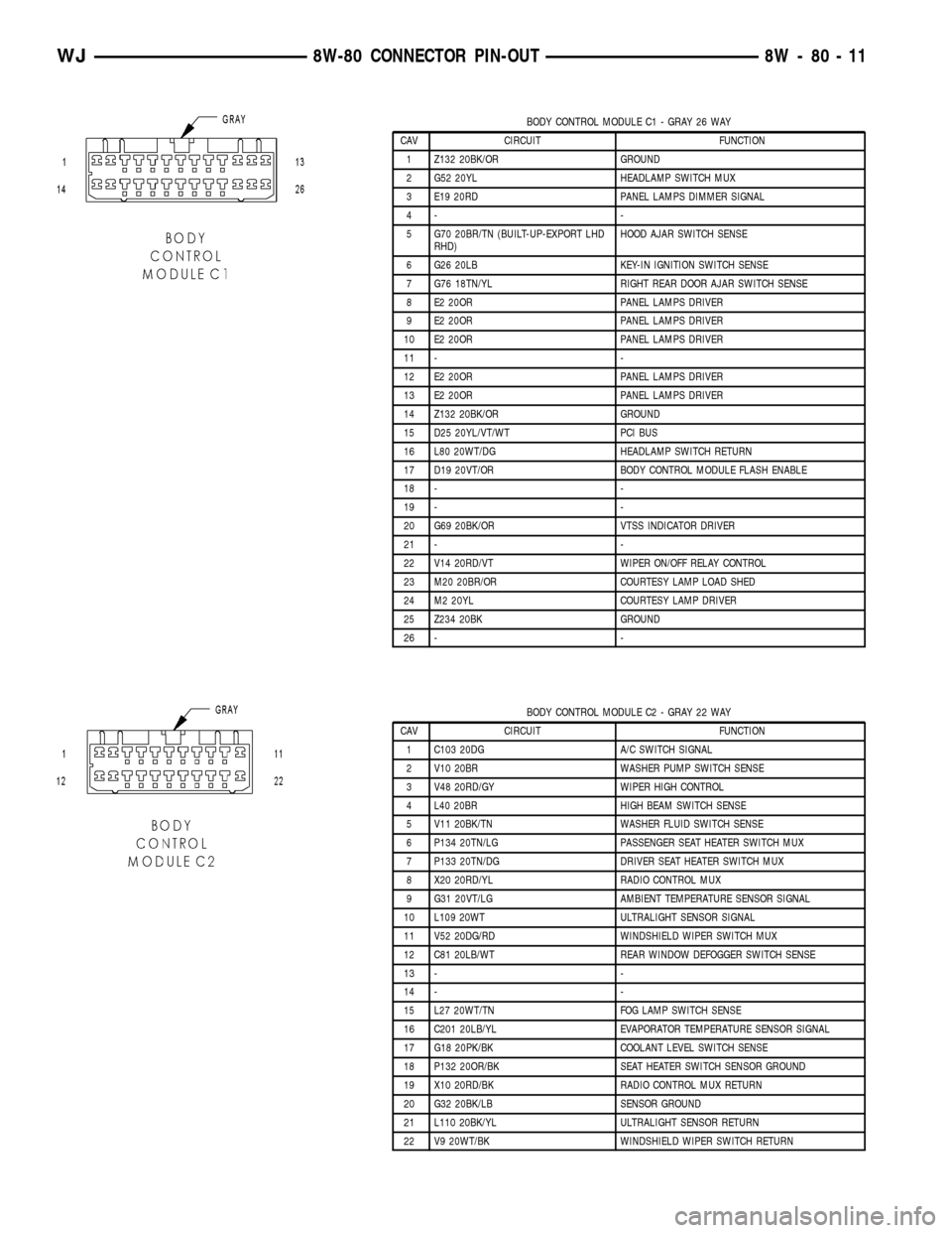
BODY CONTROL MODULE C1 - GRAY 26 WAY
CAV CIRCUIT FUNCTION
1 Z132 20BK/OR GROUND
2 G52 20YL HEADLAMP SWITCH MUX
3 E19 20RD PANEL LAMPS DIMMER SIGNAL
4- -
5 G70 20BR/TN (BUILT-UP-EXPORT LHD
RHD)HOOD AJAR SWITCH SENSE
6 G26 20LB KEY-IN IGNITION SWITCH SENSE
7 G76 18TN/YL RIGHT REAR DOOR AJAR SWITCH SENSE
8 E2 20OR PANEL LAMPS DRIVER
9 E2 20OR PANEL LAMPS DRIVER
10 E2 20OR PANEL LAMPS DRIVER
11 - -
12 E2 20OR PANEL LAMPS DRIVER
13 E2 20OR PANEL LAMPS DRIVER
14 Z132 20BK/OR GROUND
15 D25 20YL/VT/WT PCI BUS
16 L80 20WT/DG HEADLAMP SWITCH RETURN
17 D19 20VT/OR BODY CONTROL MODULE FLASH ENABLE
18 - -
19 - -
20 G69 20BK/OR VTSS INDICATOR DRIVER
21 - -
22 V14 20RD/VT WIPER ON/OFF RELAY CONTROL
23 M20 20BR/OR COURTESY LAMP LOAD SHED
24 M2 20YL COURTESY LAMP DRIVER
25 Z234 20BK GROUND
26 - -
BODY CONTROL MODULE C2 - GRAY 22 WAY
CAV CIRCUIT FUNCTION
1 C103 20DG A/C SWITCH SIGNAL
2 V10 20BR WASHER PUMP SWITCH SENSE
3 V48 20RD/GY WIPER HIGH CONTROL
4 L40 20BR HIGH BEAM SWITCH SENSE
5 V11 20BK/TN WASHER FLUID SWITCH SENSE
6 P134 20TN/LG PASSENGER SEAT HEATER SWITCH MUX
7 P133 20TN/DG DRIVER SEAT HEATER SWITCH MUX
8 X20 20RD/YL RADIO CONTROL MUX
9 G31 20VT/LG AMBIENT TEMPERATURE SENSOR SIGNAL
10 L109 20WT ULTRALIGHT SENSOR SIGNAL
11 V52 20DG/RD WINDSHIELD WIPER SWITCH MUX
12 C81 20LB/WT REAR WINDOW DEFOGGER SWITCH SENSE
13 - -
14 - -
15 L27 20WT/TN FOG LAMP SWITCH SENSE
16 C201 20LB/YL EVAPORATOR TEMPERATURE SENSOR SIGNAL
17 G18 20PK/BK COOLANT LEVEL SWITCH SENSE
18 P132 20OR/BK SEAT HEATER SWITCH SENSOR GROUND
19 X10 20RD/BK RADIO CONTROL MUX RETURN
20 G32 20BK/LB SENSOR GROUND
21 L110 20BK/YL ULTRALIGHT SENSOR RETURN
22 V9 20WT/BK WINDSHIELD WIPER SWITCH RETURN
WJ8W-80 CONNECTOR PIN-OUT 8W - 80 - 11
Page 1117 of 2199
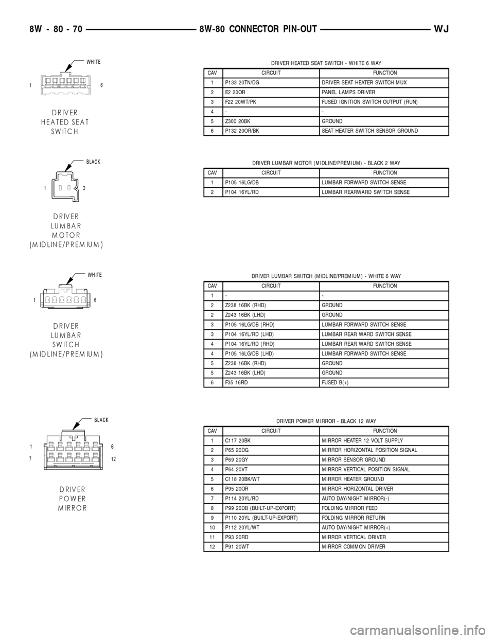
DRIVER HEATED SEAT SWITCH - WHITE 6 WAY
CAV CIRCUIT FUNCTION
1 P133 20TN/DG DRIVER SEAT HEATER SWITCH MUX
2 E2 20OR PANEL LAMPS DRIVER
3 F22 20WT/PK FUSED IGNITION SWITCH OUTPUT (RUN)
4- -
5 Z300 20BK GROUND
6 P132 20OR/BK SEAT HEATER SWITCH SENSOR GROUND
DRIVER LUMBAR MOTOR (MIDLINE/PREMIUM) - BLACK 2 WAY
CAV CIRCUIT FUNCTION
1 P105 16LG/DB LUMBAR FORWARD SWITCH SENSE
2 P104 16YL/RD LUMBAR REARWARD SWITCH SENSE
DRIVER LUMBAR SWITCH (MIDLINE/PREMIUM) - WHITE 6 WAY
CAV CIRCUIT FUNCTION
1- -
2 Z238 16BK (RHD) GROUND
2 Z243 16BK (LHD) GROUND
3 P105 16LG/DB (RHD) LUMBAR FORWARD SWITCH SENSE
3 P104 16YL/RD (LHD) LUMBAR REAR WARD SWITCH SENSE
4 P104 16YL/RD (RHD) LUMBAR REAR WARD SWITCH SENSE
4 P105 16LG/DB (LHD) LUMBAR FORWARD SWITCH SENSE
5 Z238 16BK (RHD) GROUND
5 Z243 16BK (LHD) GROUND
6 F35 16RD FUSED B(+)
DRIVER POWER MIRROR - BLACK 12 WAY
CAV CIRCUIT FUNCTION
1 C117 20BK MIRROR HEATER 12 VOLT SUPPLY
2 P65 20DG MIRROR HORIZONTAL POSITION SIGNAL
3 P69 20GY MIRROR SENSOR GROUND
4 P64 20VT MIRROR VERTICAL POSITION SIGNAL
5 C118 20BK/WT MIRROR HEATER GROUND
6 P95 20OR MIRROR HORIZONTAL DRIVER
7 P114 20YL/RD AUTO DAY/NIGHT MIRROR(-)
8 P99 20DB (BUILT-UP-EXPORT) FOLDING MIRROR FEED
9 P110 20YL (BUILT-UP-EXPORT) FOLDING MIRROR RETURN
10 P112 20YL/WT AUTO DAY/NIGHT MIRROR(+)
11 P93 20RD MIRROR VERTICAL DRIVER
12 P91 20WT MIRROR COMMON DRIVER
8W - 80 - 70 8W-80 CONNECTOR PIN-OUTWJ
Page 1142 of 2199
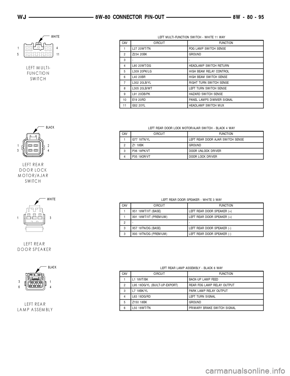
LEFT MULTI-FUNCTION SWITCH - WHITE 11 WAY
CAV CIRCUIT FUNCTION
1 L27 20WT/TN FOG LAMP SWITCH SENSE
2 Z234 20BK GROUND
3- -
4 L80 20WT/DG HEADLAMP SWITCH RETURN
5 L309 20PK/LG HIGH BEAM RELAY CONTROL
6 L40 20BR HIGH BEAM SWITCH SENSE
7 L302 20LB/YL RIGHT TURN SWITCH SENSE
8 L305 20LB/WT LEFT TURN SWITCH SENSE
9 L91 20DB/PK HAZARD SWITCH SENSE
10 E19 20RD PANEL LAMPS DIMMER SIGNAL
11 G52 20YL HEADLAMP SWITCH MUX
LEFT REAR DOOR LOCK MOTOR/AJAR SWITCH - BLACK 4 WAY
CAV CIRCUIT FUNCTION
1 G77 18TN/YL LEFT REAR DOOR AJAR SWITCH SENSE
2 Z1 18BK GROUND
3 P36 18PK/VT DOOR UNLOCK DRIVER
4 P35 18OR/VT DOOR LOCK DRIVER
LEFT REAR DOOR SPEAKER - WHITE 3 WAY
CAV CIRCUIT FUNCTION
1 X51 18WT/VT (BASE) LEFT REAR DOOR SPEAKER (+)
1 X91 18WT/VT (PREMIUM) LEFT REAR DOOR SPEAKER (+)
2- -
3 X57 18TN/DG (BASE) LEFT REAR DOOR SPEAKER (-)
3 X93 18TN/DG (PREMIUM) LEFT REAR DOOR SPEAKER (-)
LEFT REAR LAMP ASSEMBLY - BLACK 6 WAY
CAV CIRCUIT FUNCTION
1 L1 18VT/BK BACK-UP LAMP FEED
2 L95 18DG/YL (BUILT-UP-EXPORT) REAR FOG LAMP RELAY OUTPUT
3 L7 18BK/YL PARK LAMP RELAY OUTPUT
4 L63 18DG/RD LEFT TURN SIGNAL
5 Z150 18BK GROUND
6 L50 18WT/TN PRIMARY BRAKE SWITCH SIGNAL
WJ8W-80 CONNECTOR PIN-OUT 8W - 80 - 95