intake JEEP GRAND CHEROKEE 2002 WJ / 2.G Workshop Manual
[x] Cancel search | Manufacturer: JEEP, Model Year: 2002, Model line: GRAND CHEROKEE, Model: JEEP GRAND CHEROKEE 2002 WJ / 2.GPages: 2199, PDF Size: 76.01 MB
Page 2158 of 2199
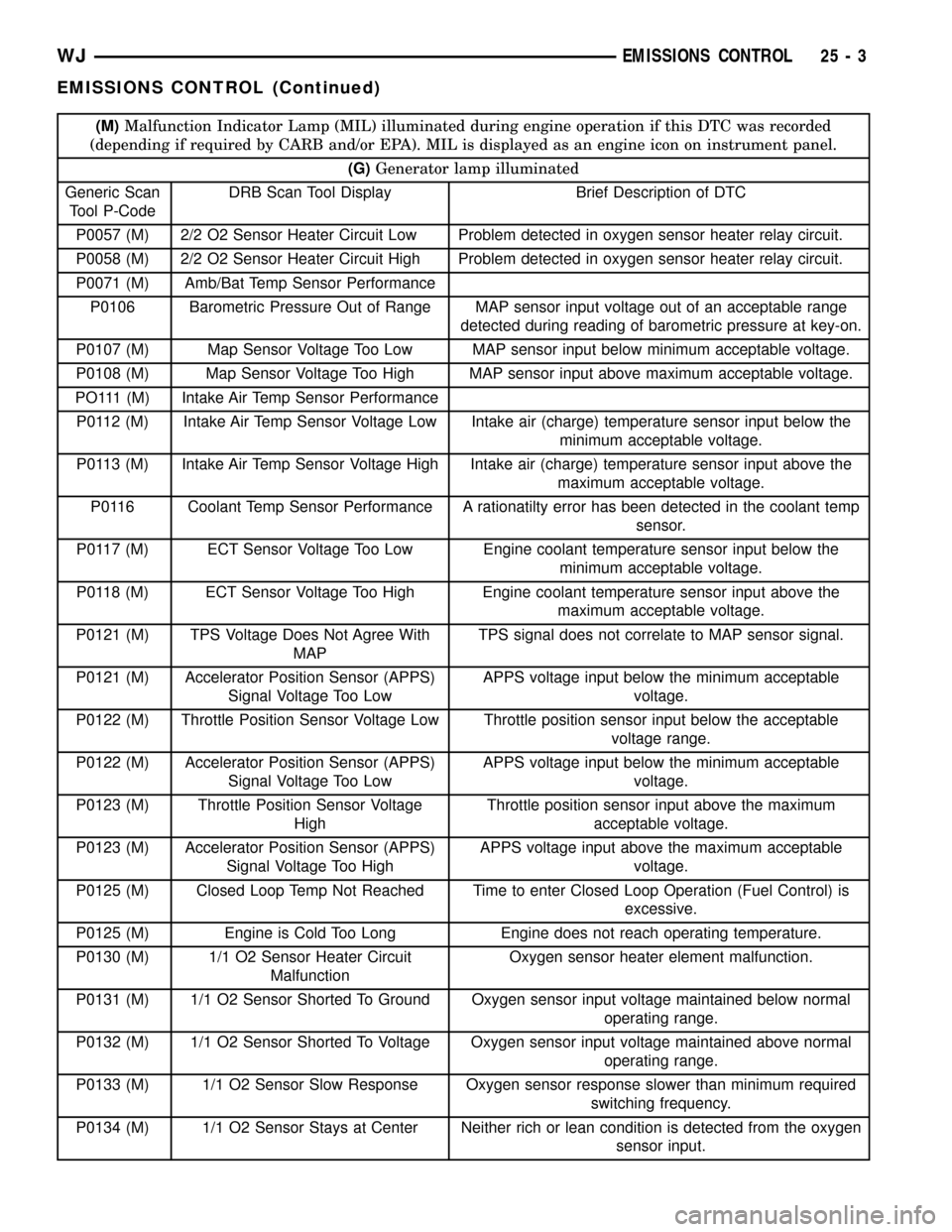
(M)Malfunction Indicator Lamp (MIL) illuminated during engine operation if this DTC was recorded
(depending if required by CARB and/or EPA). MIL is displayed as an engine icon on instrument panel.
(G)Generator lamp illuminated
Generic Scan
Tool P-CodeDRB Scan Tool Display Brief Description of DTC
P0057 (M) 2/2 O2 Sensor Heater Circuit Low Problem detected in oxygen sensor heater relay circuit.
P0058 (M) 2/2 O2 Sensor Heater Circuit High Problem detected in oxygen sensor heater relay circuit.
P0071 (M) Amb/Bat Temp Sensor Performance
P0106 Barometric Pressure Out of Range MAP sensor input voltage out of an acceptable range
detected during reading of barometric pressure at key-on.
P0107 (M) Map Sensor Voltage Too Low MAP sensor input below minimum acceptable voltage.
P0108 (M) Map Sensor Voltage Too High MAP sensor input above maximum acceptable voltage.
PO111 (M) Intake Air Temp Sensor Performance
P0112 (M) Intake Air Temp Sensor Voltage Low Intake air (charge) temperature sensor input below the
minimum acceptable voltage.
P0113 (M) Intake Air Temp Sensor Voltage High Intake air (charge) temperature sensor input above the
maximum acceptable voltage.
P0116 Coolant Temp Sensor Performance A rationatilty error has been detected in the coolant temp
sensor.
P0117 (M) ECT Sensor Voltage Too Low Engine coolant temperature sensor input below the
minimum acceptable voltage.
P0118 (M) ECT Sensor Voltage Too High Engine coolant temperature sensor input above the
maximum acceptable voltage.
P0121 (M) TPS Voltage Does Not Agree With
MAPTPS signal does not correlate to MAP sensor signal.
P0121 (M) Accelerator Position Sensor (APPS)
Signal Voltage Too LowAPPS voltage input below the minimum acceptable
voltage.
P0122 (M) Throttle Position Sensor Voltage Low Throttle position sensor input below the acceptable
voltage range.
P0122 (M) Accelerator Position Sensor (APPS)
Signal Voltage Too LowAPPS voltage input below the minimum acceptable
voltage.
P0123 (M) Throttle Position Sensor Voltage
HighThrottle position sensor input above the maximum
acceptable voltage.
P0123 (M) Accelerator Position Sensor (APPS)
Signal Voltage Too HighAPPS voltage input above the maximum acceptable
voltage.
P0125 (M) Closed Loop Temp Not Reached Time to enter Closed Loop Operation (Fuel Control) is
excessive.
P0125 (M) Engine is Cold Too Long Engine does not reach operating temperature.
P0130 (M) 1/1 O2 Sensor Heater Circuit
MalfunctionOxygen sensor heater element malfunction.
P0131 (M) 1/1 O2 Sensor Shorted To Ground Oxygen sensor input voltage maintained below normal
operating range.
P0132 (M) 1/1 O2 Sensor Shorted To Voltage Oxygen sensor input voltage maintained above normal
operating range.
P0133 (M) 1/1 O2 Sensor Slow Response Oxygen sensor response slower than minimum required
switching frequency.
P0134 (M) 1/1 O2 Sensor Stays at Center Neither rich or lean condition is detected from the oxygen
sensor input.
WJEMISSIONS CONTROL 25 - 3
EMISSIONS CONTROL (Continued)
Page 2162 of 2199
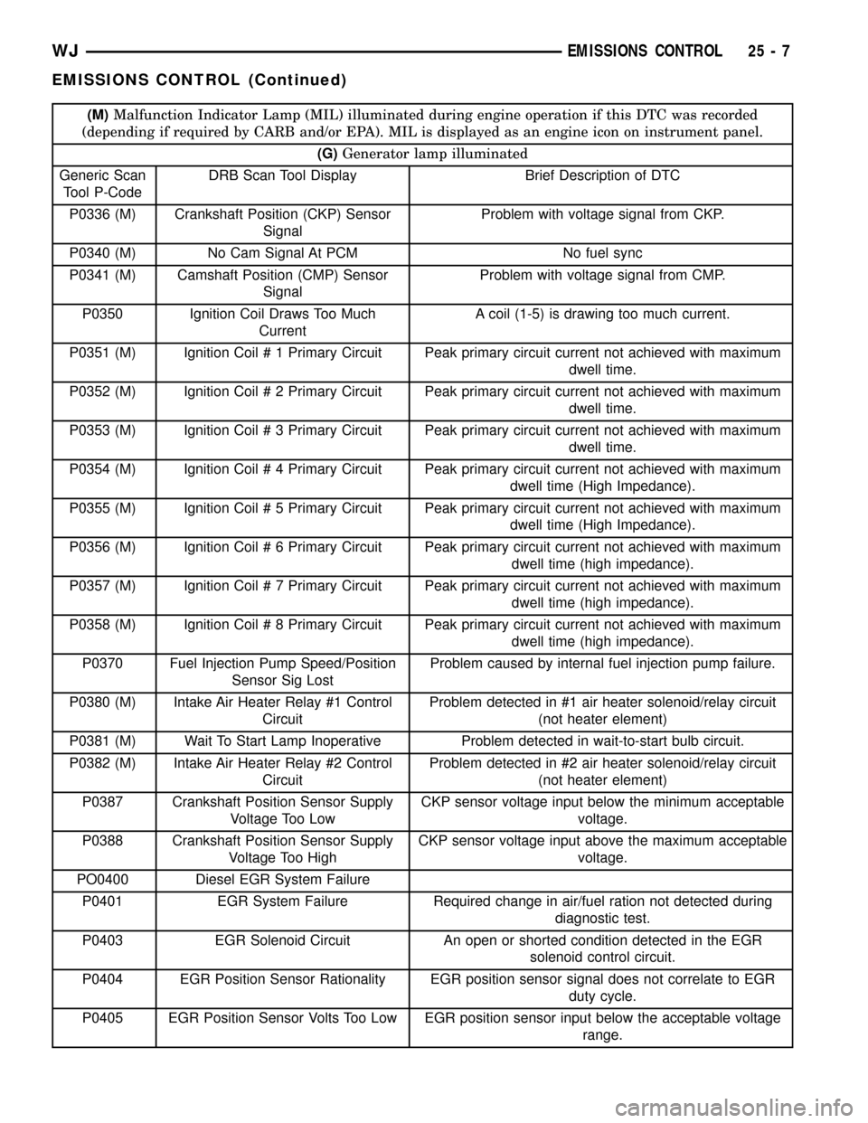
(M)Malfunction Indicator Lamp (MIL) illuminated during engine operation if this DTC was recorded
(depending if required by CARB and/or EPA). MIL is displayed as an engine icon on instrument panel.
(G)Generator lamp illuminated
Generic Scan
Tool P-CodeDRB Scan Tool Display Brief Description of DTC
P0336 (M) Crankshaft Position (CKP) Sensor
SignalProblem with voltage signal from CKP.
P0340 (M) No Cam Signal At PCM No fuel sync
P0341 (M) Camshaft Position (CMP) Sensor
SignalProblem with voltage signal from CMP.
P0350 Ignition Coil Draws Too Much
CurrentA coil (1-5) is drawing too much current.
P0351 (M) Ignition Coil # 1 Primary Circuit Peak primary circuit current not achieved with maximum
dwell time.
P0352 (M) Ignition Coil # 2 Primary Circuit Peak primary circuit current not achieved with maximum
dwell time.
P0353 (M) Ignition Coil # 3 Primary Circuit Peak primary circuit current not achieved with maximum
dwell time.
P0354 (M) Ignition Coil # 4 Primary Circuit Peak primary circuit current not achieved with maximum
dwell time (High Impedance).
P0355 (M) Ignition Coil # 5 Primary Circuit Peak primary circuit current not achieved with maximum
dwell time (High Impedance).
P0356 (M) Ignition Coil # 6 Primary Circuit Peak primary circuit current not achieved with maximum
dwell time (high impedance).
P0357 (M) Ignition Coil # 7 Primary Circuit Peak primary circuit current not achieved with maximum
dwell time (high impedance).
P0358 (M) Ignition Coil # 8 Primary Circuit Peak primary circuit current not achieved with maximum
dwell time (high impedance).
P0370 Fuel Injection Pump Speed/Position
Sensor Sig LostProblem caused by internal fuel injection pump failure.
P0380 (M) Intake Air Heater Relay #1 Control
CircuitProblem detected in #1 air heater solenoid/relay circuit
(not heater element)
P0381 (M) Wait To Start Lamp Inoperative Problem detected in wait-to-start bulb circuit.
P0382 (M) Intake Air Heater Relay #2 Control
CircuitProblem detected in #2 air heater solenoid/relay circuit
(not heater element)
P0387 Crankshaft Position Sensor Supply
Voltage Too LowCKP sensor voltage input below the minimum acceptable
voltage.
P0388 Crankshaft Position Sensor Supply
Voltage Too HighCKP sensor voltage input above the maximum acceptable
voltage.
PO0400 Diesel EGR System Failure
P0401 EGR System Failure Required change in air/fuel ration not detected during
diagnostic test.
P0403 EGR Solenoid Circuit An open or shorted condition detected in the EGR
solenoid control circuit.
P0404 EGR Position Sensor Rationality EGR position sensor signal does not correlate to EGR
duty cycle.
P0405 EGR Position Sensor Volts Too Low EGR position sensor input below the acceptable voltage
range.
WJEMISSIONS CONTROL 25 - 7
EMISSIONS CONTROL (Continued)
Page 2166 of 2199
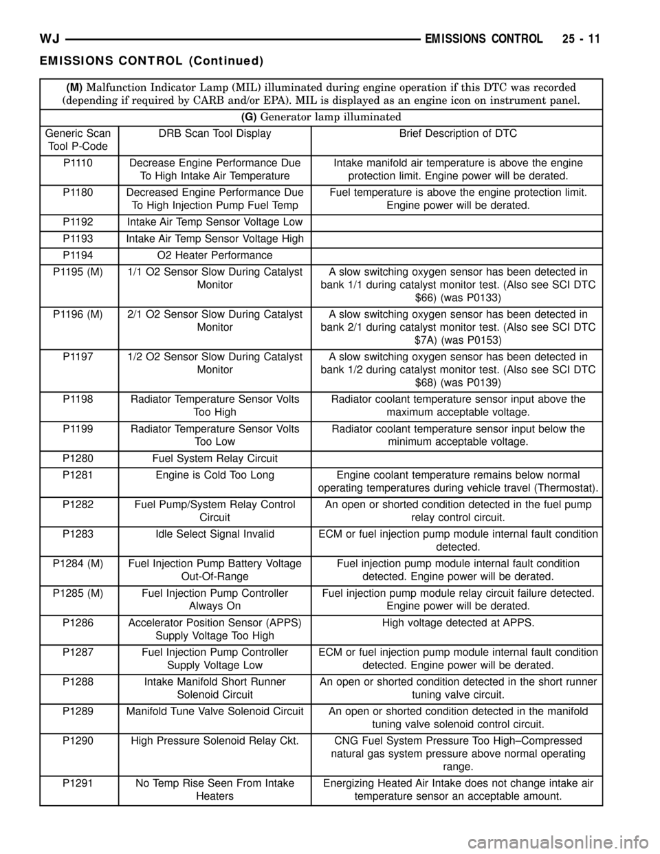
(M)Malfunction Indicator Lamp (MIL) illuminated during engine operation if this DTC was recorded
(depending if required by CARB and/or EPA). MIL is displayed as an engine icon on instrument panel.
(G)Generator lamp illuminated
Generic Scan
Tool P-CodeDRB Scan Tool Display Brief Description of DTC
P1110 Decrease Engine Performance Due
To High Intake Air TemperatureIntake manifold air temperature is above the engine
protection limit. Engine power will be derated.
P1180 Decreased Engine Performance Due
To High Injection Pump Fuel TempFuel temperature is above the engine protection limit.
Engine power will be derated.
P1192 Intake Air Temp Sensor Voltage Low
P1193 Intake Air Temp Sensor Voltage High
P1194 O2 Heater Performance
P1195 (M) 1/1 O2 Sensor Slow During Catalyst
MonitorA slow switching oxygen sensor has been detected in
bank 1/1 during catalyst monitor test. (Also see SCI DTC
$66) (was P0133)
P1196 (M) 2/1 O2 Sensor Slow During Catalyst
MonitorA slow switching oxygen sensor has been detected in
bank 2/1 during catalyst monitor test. (Also see SCI DTC
$7A) (was P0153)
P1197 1/2 O2 Sensor Slow During Catalyst
MonitorA slow switching oxygen sensor has been detected in
bank 1/2 during catalyst monitor test. (Also see SCI DTC
$68) (was P0139)
P1198 Radiator Temperature Sensor Volts
Too HighRadiator coolant temperature sensor input above the
maximum acceptable voltage.
P1199 Radiator Temperature Sensor Volts
Too LowRadiator coolant temperature sensor input below the
minimum acceptable voltage.
P1280 Fuel System Relay Circuit
P1281 Engine is Cold Too Long Engine coolant temperature remains below normal
operating temperatures during vehicle travel (Thermostat).
P1282 Fuel Pump/System Relay Control
CircuitAn open or shorted condition detected in the fuel pump
relay control circuit.
P1283 Idle Select Signal Invalid ECM or fuel injection pump module internal fault condition
detected.
P1284 (M) Fuel Injection Pump Battery Voltage
Out-Of-RangeFuel injection pump module internal fault condition
detected. Engine power will be derated.
P1285 (M) Fuel Injection Pump Controller
Always OnFuel injection pump module relay circuit failure detected.
Engine power will be derated.
P1286 Accelerator Position Sensor (APPS)
Supply Voltage Too HighHigh voltage detected at APPS.
P1287 Fuel Injection Pump Controller
Supply Voltage LowECM or fuel injection pump module internal fault condition
detected. Engine power will be derated.
P1288 Intake Manifold Short Runner
Solenoid CircuitAn open or shorted condition detected in the short runner
tuning valve circuit.
P1289 Manifold Tune Valve Solenoid Circuit An open or shorted condition detected in the manifold
tuning valve solenoid control circuit.
P1290 High Pressure Solenoid Relay Ckt. CNG Fuel System Pressure Too High±Compressed
natural gas system pressure above normal operating
range.
P1291 No Temp Rise Seen From Intake
HeatersEnergizing Heated Air Intake does not change intake air
temperature sensor an acceptable amount.
WJEMISSIONS CONTROL 25 - 11
EMISSIONS CONTROL (Continued)
Page 2167 of 2199
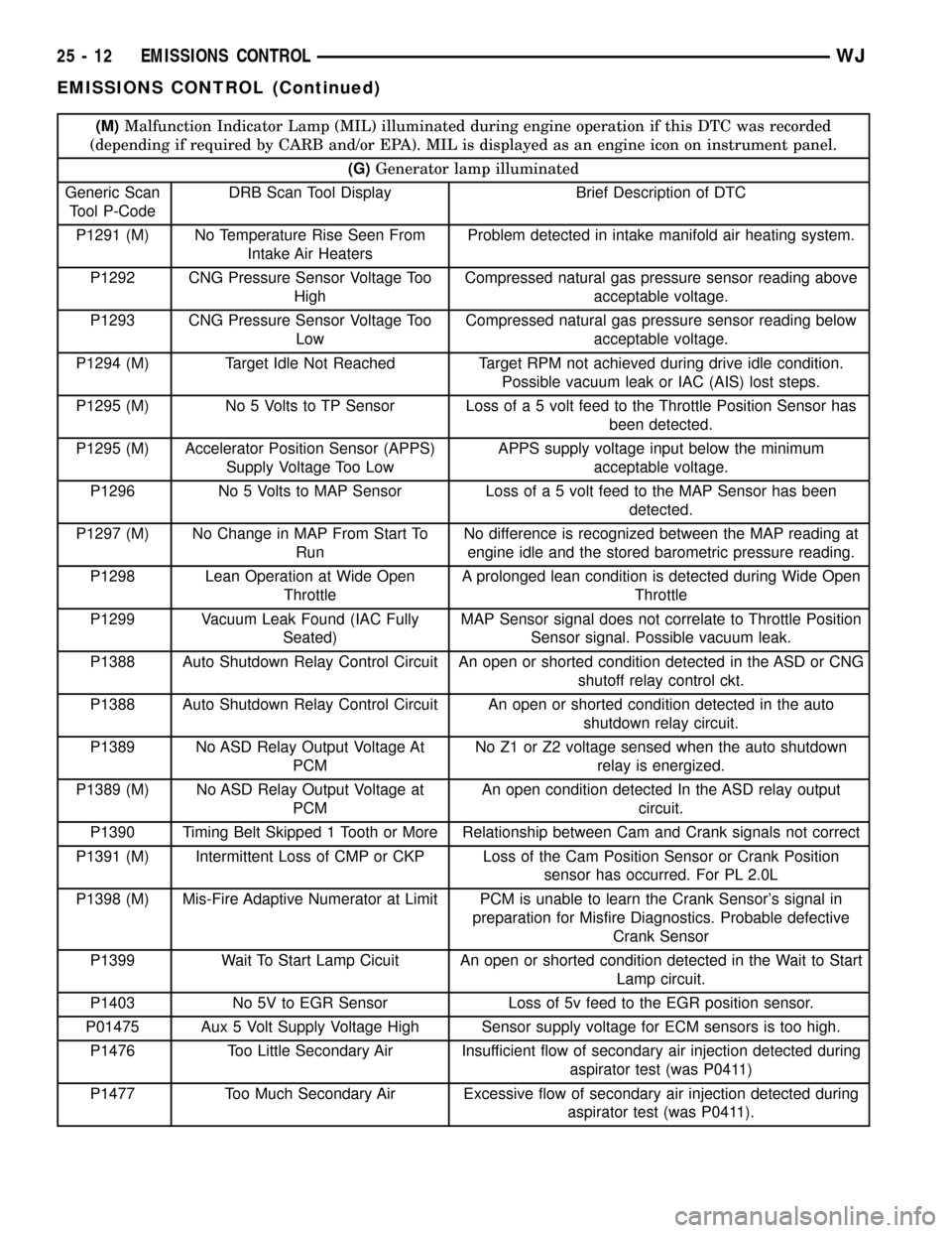
(M)Malfunction Indicator Lamp (MIL) illuminated during engine operation if this DTC was recorded
(depending if required by CARB and/or EPA). MIL is displayed as an engine icon on instrument panel.
(G)Generator lamp illuminated
Generic Scan
Tool P-CodeDRB Scan Tool Display Brief Description of DTC
P1291 (M) No Temperature Rise Seen From
Intake Air HeatersProblem detected in intake manifold air heating system.
P1292 CNG Pressure Sensor Voltage Too
HighCompressed natural gas pressure sensor reading above
acceptable voltage.
P1293 CNG Pressure Sensor Voltage Too
LowCompressed natural gas pressure sensor reading below
acceptable voltage.
P1294 (M) Target Idle Not Reached Target RPM not achieved during drive idle condition.
Possible vacuum leak or IAC (AIS) lost steps.
P1295 (M) No 5 Volts to TP Sensor Loss of a 5 volt feed to the Throttle Position Sensor has
been detected.
P1295 (M) Accelerator Position Sensor (APPS)
Supply Voltage Too LowAPPS supply voltage input below the minimum
acceptable voltage.
P1296 No 5 Volts to MAP Sensor Loss of a 5 volt feed to the MAP Sensor has been
detected.
P1297 (M) No Change in MAP From Start To
RunNo difference is recognized between the MAP reading at
engine idle and the stored barometric pressure reading.
P1298 Lean Operation at Wide Open
ThrottleA prolonged lean condition is detected during Wide Open
Throttle
P1299 Vacuum Leak Found (IAC Fully
Seated)MAP Sensor signal does not correlate to Throttle Position
Sensor signal. Possible vacuum leak.
P1388 Auto Shutdown Relay Control Circuit An open or shorted condition detected in the ASD or CNG
shutoff relay control ckt.
P1388 Auto Shutdown Relay Control Circuit An open or shorted condition detected in the auto
shutdown relay circuit.
P1389 No ASD Relay Output Voltage At
PCMNo Z1 or Z2 voltage sensed when the auto shutdown
relay is energized.
P1389 (M) No ASD Relay Output Voltage at
PCMAn open condition detected In the ASD relay output
circuit.
P1390 Timing Belt Skipped 1 Tooth or More Relationship between Cam and Crank signals not correct
P1391 (M) Intermittent Loss of CMP or CKP Loss of the Cam Position Sensor or Crank Position
sensor has occurred. For PL 2.0L
P1398 (M) Mis-Fire Adaptive Numerator at Limit PCM is unable to learn the Crank Sensor's signal in
preparation for Misfire Diagnostics. Probable defective
Crank Sensor
P1399 Wait To Start Lamp Cicuit An open or shorted condition detected in the Wait to Start
Lamp circuit.
P1403 No 5V to EGR Sensor Loss of 5v feed to the EGR position sensor.
P01475 Aux 5 Volt Supply Voltage High Sensor supply voltage for ECM sensors is too high.
P1476 Too Little Secondary Air Insufficient flow of secondary air injection detected during
aspirator test (was P0411)
P1477 Too Much Secondary Air Excessive flow of secondary air injection detected during
aspirator test (was P0411).
25 - 12 EMISSIONS CONTROLWJ
EMISSIONS CONTROL (Continued)
Page 2179 of 2199

EVAPORATIVE EMISSIONS
TABLE OF CONTENTS
page page
EVAPORATIVE EMISSIONS
DESCRIPTION
DESCRIPTION - EVAPORATION CONTROL
SYSTEM............................24
DESCRIPTION - CCV SYSTEM...........25
DESCRIPTION - PCV SYSTEM...........25
OPERATION
OPERATION - 4.0L CCV SYSTEM.........26
OPERATION - 4.7L PCV SYSTEM.........26
SPECIFICATIONS
TORQUE - EVAPORATION SYSTEM.......27
CCV HOSE
DIAGNOSIS AND TESTING - CCV SYSTEM -
4.0L................................28
REMOVAL - FIXED ORIFICE FITTING........28
INSTALLATION - FIXED ORIFICE FITTING....29
EVAP/PURGE SOLENOID
DESCRIPTION.........................29
OPERATION...........................29
REMOVAL.............................29
INSTALLATION.........................29
FUEL FILLER CAP
DESCRIPTION.........................29
OPERATION...........................29REMOVAL.............................29
LEAK DETECTION PUMP
DESCRIPTION.........................30
OPERATION...........................31
DIAGNOSIS AND TESTING - ENABLING
CONDITIONS TO RUN EVAP LEAK
DETECTION TEST.....................32
REMOVAL.............................35
INSTALLATION.........................35
ORVR
DESCRIPTION.........................37
OPERATION...........................37
P C V VA LV E
DIAGNOSIS AND TESTING - PCV VALVE/PCV
SYSTEM - 4.7L.......................37
REMOVAL - PCV VALVE - 4.7L.............39
INSTALLATION - PCV VALVE - 4.7L.........39
VACUUM LINES
DESCRIPTION.........................39
VAPOR CANISTER
DESCRIPTION.........................39
OPERATION...........................39
REMOVAL.............................40
INSTALLATION.........................40
EVAPORATIVE EMISSIONS
DESCRIPTION
DESCRIPTION - EVAPORATION CONTROL
SYSTEM
The evaporation control system prevents the emis-
sion of fuel tank vapors into the atmosphere. When
fuel evaporates in the fuel tank, the vapors pass
through the control valve, through the fuel manage-
ment valve, and through vent hoses and tubes to a
charcoal filled evaporative canister. The canister tem-
porarily holds the vapors. The Powertrain Control
Module (PCM) allows intake manifold vacuum todraw vapors into the combustion chambers during
certain operating conditions.
Gas powered engines use a duty cycle purge sys-
tem. The PCM controls vapor flow by operating the
duty cycle EVAP purge solenoid. Refer to Duty Cycle
EVAP Canister Purge Solenoid.
When equipped with certain emissions packages, a
Leak Detection Pump (LDP) will be used as part of
the evaporative system for OBD II requirements.
Also refer to Leak Detection Pump.
Vehicles powered with gasoline engines are also
equipped with ORVR (On-Board Refueling Vapor
Recovery). Refer to ORVR for additional information.
25 - 24 EVAPORATIVE EMISSIONSWJ
Page 2181 of 2199

²a PCV valve mounted to the oil filler housing
(Fig. 3). The PCV valve is sealed to the oil filler
housing with an o-ring.
²the air cleaner housing
²two interconnected breathers threaded into the
rear of each cylinder head (Fig. 4).
²tubes and hose to connect the system compo-
nents.
OPERATION
OPERATION - 4.0L CCV SYSTEM
The CCV system performs the same function as a
conventional PCV system, but does not use a vacuum
controlled PCV valve.
The fixed orifice fitting meters the amount of
crankcase vapors drawn out of the engine.
When the engine is operating, fresh air enters the
engine and mixes with crankcase vapors. Engine vac-uum draws the vapor/air mixture through the fixed
orifice and into the intake manifold. The vapors are
then consumed during engine combustion.
OPERATION - 4.7L PCV SYSTEM
The PCV system operates by engine intake mani-
fold vacuum. Filtered air is routed into the crankcase
through the air cleaner hose and crankcase breath-
ers. The metered air, along with crankcase vapors,
are drawn through the PCV valve and into a passage
in the intake manifold. The PCV system manages
crankcase pressure and meters blow-by gases to the
intake system, reducing engine sludge formation.
The PCV valve contains a spring loaded plunger.
This plunger meters the amount of crankcase vapors
routed into the combustion chamber based on intake
manifold vacuum.
TYPICALPCV valves are shown in (Fig. 5), (Fig.
6) and (Fig. 7).
When the engine is not operating, or during an
engine pop-back, the spring forces the plunger back
against the seat (Fig. 5). This will prevent vapors
from flowing through the valve.
Fig. 3 PCV Valve/Oil Filler Tube (Housing)Ð4.7L
Engine
1 - O-RING
2 - LOCATING TABS
3 - CAM LOCK
4 - OIL FILLER TUBE
5 - PCV LINE/HOSE
6 - P C V VA LV E
Fig. 4 PCV System Hoses/TubesÐ4.7L Engine
1 - FRESH AIR FITTING
2 - CONNECTING TUBES/HOSES
3 - CRANKCASE BREATHERS (2)
4 - RUBBER HOSE
5 - AIR CLEANER RESONATOR
25 - 26 EVAPORATIVE EMISSIONSWJ
EVAPORATIVE EMISSIONS (Continued)
Page 2182 of 2199
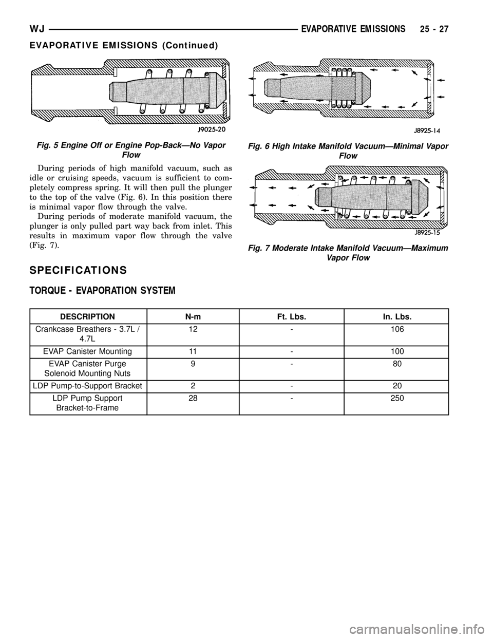
During periods of high manifold vacuum, such as
idle or cruising speeds, vacuum is sufficient to com-
pletely compress spring. It will then pull the plunger
to the top of the valve (Fig. 6). In this position there
is minimal vapor flow through the valve.
During periods of moderate manifold vacuum, the
plunger is only pulled part way back from inlet. This
results in maximum vapor flow through the valve
(Fig. 7).
SPECIFICATIONS
TORQUE - EVAPORATION SYSTEM
DESCRIPTION N-m Ft. Lbs. In. Lbs.
Crankcase Breathers - 3.7L /
4.7L12 - 106
EVAP Canister Mounting 11 - 100
EVAP Canister Purge
Solenoid Mounting Nuts9- 80
LDP Pump-to-Support Bracket 2 - 20
LDP Pump Support
Bracket-to-Frame28 - 250
Fig. 5 Engine Off or Engine Pop-BackÐNo Vapor
FlowFig. 6 High Intake Manifold VacuumÐMinimal Vapor
Flow
Fig. 7 Moderate Intake Manifold VacuumÐMaximum
Vapor Flow
WJEVAPORATIVE EMISSIONS 25 - 27
EVAPORATIVE EMISSIONS (Continued)
Page 2183 of 2199

CCV HOSE
DIAGNOSIS AND TESTING - CCV SYSTEM -
4.0L
Before attempting diagnosis, be sure locations of
fixed orifice fitting and air inlet fitting (Fig. 8) have
not been inadvertently exchanged. The fixed orifice
fitting is light grey in color and is located atrearof
valve cover. The air inlet fitting is black in color and
is located atfrontof valve cover.
(1) Pull fixed orifice fitting (Fig. 8) from valve
cover and leave tube attached.
(2) Start engine and bring to idle speed.
(3) If fitting is not plugged, a hissing noise will be
heard as air passes through fitting orifice. Also, a
strong vacuum should be felt with a finger placed at
fitting inlet.
(4) If vacuum is not present, remove fitting orifice
fitting from tube. Start engine. If vacuum can now be
felt, replace fixed orifice fitting. Do not attempt to
clean plastic fitting.
(5) If vacuum is still not felt at hose, check line/
hose for kinks or for obstruction. If necessary, clean
out intake manifold fitting at intake manifold. Do
this by turning a 1/4 inch drill (by hand) through the
fitting to dislodge any solid particles. Blow out thefitting with shop air. If necessary, use a smaller drill
to avoid removing any metal from the fitting.
(6) Return fixed orifice fitting to valve cover and
leave tube attached.
(7) Disconnect air inlet fitting and its attached
hose at front of valve cover (Fig. 8). Start engine and
bring to idle speed. Hold a piece of stiff paper (such
as a parts tag) loosely over the rubber grommet
(opening) of the disconnected air inlet fitting.
(8) The paper should be drawn against the rubber
grommet with noticeable force. This will be after
allowing approximately one minute for crankcase
pressure to reduce.
(9) If vacuum is not present, check breather hoses/
tubes/lines for obstructions or restrictions.
(10) After testing, reconnect all system hoses/
tubes/lines.
REMOVAL - FIXED ORIFICE FITTING
When installing fixed orifice fitting, be sure loca-
tions of fixed orifice fitting and air inlet fitting (Fig.
9) have not been inadvertently exchanged. The fixed
orifice fitting is light grey in color and is located at
rearof valve cover. The air inlet fitting is black in
color and is located atfrontof valve cover.
(1) Pull fixed orifice fitting (Fig. 9) from valve
cover grommet.
(2) Separate fitting from CCV breather tube.
Fig. 8 Fixed Orifice Fitting and CCV SystemÐ4.0L
Engine
1 - AIR INLET FITTING
2 - FIXED ORIFICE FITTING
3 - CCV BREATHER TUBE (REAR)
4 - INT. MAN. FITTING
5 - CCV BREATHER TUBE (FRONT)
Fig. 9 FIXED ORIFICE FITTING - 4.0L
1 - AIR INLET FITTING
2 - FIXED ORIFICE FITTING
3 - CCV BREATHER TUBE (REAR)
4 - INT. MAN. FITTING
5 - CCV BREATHER TUBE (FRONT)
25 - 28 EVAPORATIVE EMISSIONSWJ
Page 2184 of 2199

INSTALLATION - FIXED ORIFICE FITTING
When installing fixed orifice fitting, be sure loca-
tions of fixed orifice fitting and air inlet fitting (Fig.
9) have not been inadvertently exchanged. The fixed
orifice fitting is light grey in color and is located at
rearof valve cover. The air inlet fitting is black in
color and is located atfrontof valve cover.
(1) Connect fitting to CCV breather tube.
(2) Return fixed orifice fitting to valve cover grom-
met.
EVAP/PURGE SOLENOID
DESCRIPTION
The duty cycle EVAP canister purge solenoid (DCP)
regulates the rate of vapor flow from the EVAP can-
ister to the intake manifold. The Powertrain Control
Module (PCM) operates the solenoid.
OPERATION
During the cold start warm-up period and the hot
start time delay, the PCM does not energize the sole-
noid. When de-energized, no vapors are purged. The
PCM de-energizes the solenoid during open loop oper-
ation.
The engine enters closed loop operation after it
reaches a specified temperature and the time delay
ends. During closed loop operation, the PCM cycles
(energizes and de-energizes) the solenoid 5 or 10
times per second, depending upon operating condi-
tions. The PCM varies the vapor flow rate by chang-
ing solenoid pulse width. Pulse width is the amount
of time that the solenoid is energized. The PCM
adjusts solenoid pulse width based on engine operat-
ing condition.
REMOVAL
The duty cycle evaporative (EVAP) canister purge
solenoid is located in the engine compartment near
the brake master cylinder (Fig. 10).
(1) Disconnect electrical connector at solenoid.
(2) Disconnect vacuum lines at solenoid.
(3) Lift solenoid slot (Fig. 10) from mounting
bracket for removal.
INSTALLATION
(1) Position solenoid slot to mounting bracket.
(2) Connect vacuum lines to solenoid. Be sure vac-
uum lines are firmly connected and not leaking or
damaged. If leaking, a Diagnostic Trouble Code
(DTC) may be set with certain emission packages.
(3) Connect electrical connector to solenoid.
FUEL FILLER CAP
DESCRIPTION
The plastic fuel tank filler tube cap is threaded
onto the end of the fuel fill tube. Certain models are
equipped with a 1/4 turn cap.
OPERATION
The loss of any fuel or vapor out of fuel filler tube
is prevented by the use of a pressure-vacuum fuel fill
cap. Relief valves inside the cap will release fuel tank
pressure at predetermined pressures. Fuel tank vac-
uum will also be released at predetermined values.
This cap must be replaced by a similar unit if
replacement is necessary. This is in order for the sys-
tem to remain effective.
CAUTION: Remove fill cap before servicing any fuel
system component to relieve tank pressure. If
equipped with a California emissions package and a
Leak Detection Pump (LDP), the cap must be tight-
ened securely. If cap is left loose, a Diagnostic
Trouble Code (DTC) may be set.
REMOVAL
If replacement of the 1/4 turn fuel tank filler tube
cap is necessary, it must be replaced with an identi-
cal cap to be sure of correct system operation.
Fig. 10 EVAP/PURGE SOLENOID LOCATION
1 - BRAKE MASTER CYLINDER
2 - EVAP SOLENOID
3 - SLOT
4 - ELEC. CONNEC.
5 - VACUUM LINE CONNEC.
6 - TEST PORT
WJEVAPORATIVE EMISSIONS 25 - 29
CCV HOSE (Continued)
Page 2185 of 2199

CAUTION: Remove the fuel tank filler tube cap to
relieve fuel tank pressure. The cap must be
removed prior to disconnecting any fuel system
component or before draining the fuel tank.
LEAK DETECTION PUMP
DESCRIPTION
The evaporative emission system is designed to
prevent the escape of fuel vapors from the fuel sys-
tem (Fig. 11). Leaks in the system, even small ones,
can allow fuel vapors to escape into the atmosphere.
Government regulations require onboard testing to
make sure that the evaporative (EVAP) system is
functioning properly. The leak detection system tests
for EVAP system leaks and blockage. It also performs
self-diagnostics. During self-diagnostics, the Power-
train Control Module (PCM) first checks the Leak
Detection Pump (LDP) for electrical and mechanical
faults. If the first checks pass, the PCM then uses
the LDP to seal the vent valve and pump air into the
system to pressurize it. If a leak is present, the PCM
will continue pumping the LDP to replace the air
that leaks out. The PCM determines the size of the
leak based on how fast/long it must pump the LDP
as it tries to maintain pressure in the system.
EVAP LEAK DETECTION SYSTEM COMPONENTS
Service Port: Used with special tools like the Miller
Evaporative Emissions Leak Detector (EELD) to test
for leaks in the system.
EVAP Purge Solenoid: The PCM uses the EVAP
purge solenoid to control purging of excess fuel
vapors stored in the EVAP canister. It remains closed
during leak testing to prevent loss of pressure.
EVAP Canister: The EVAP canister stores fuel
vapors from the fuel tank for purging.
EVAP Purge Orifice: Limits purge volume.
EVAP System Air Filter: Provides air to the LDP
for pressurizing the system. It filters out dirt while
allowing a vent to atmosphere for the EVAP system.
Fig. 11 TYPICAL SYSTEM COMPONENTS
1 - Throttle Body
2 - Service Vacuum Supply Tee (SVST)
3 - LDP Solenoid
4 - EVAP System Air Filter
5 - LDP Vent Valve
6 - EVAP Purge Orifice
7 - EVAP Purge Solenoid
8 - Service Port
9 - To Fuel Tank
10 - EVAP Canister
11 - LDP
12 - Intake Air Plenum
25 - 30 EVAPORATIVE EMISSIONSWJ
FUEL FILLER CAP (Continued)