power amp JEEP GRAND CHEROKEE 2002 WJ / 2.G Workshop Manual
[x] Cancel search | Manufacturer: JEEP, Model Year: 2002, Model line: GRAND CHEROKEE, Model: JEEP GRAND CHEROKEE 2002 WJ / 2.GPages: 2199, PDF Size: 76.01 MB
Page 1179 of 2199
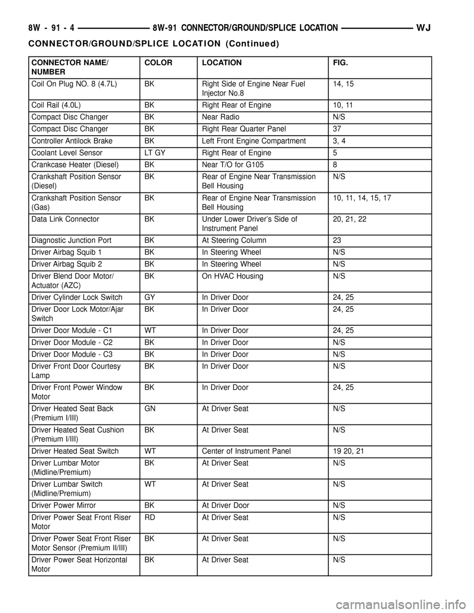
CONNECTOR NAME/
NUMBERCOLOR LOCATION FIG.
Coil On Plug NO. 8 (4.7L) BK Right Side of Engine Near Fuel
Injector No.814, 15
Coil Rail (4.0L) BK Right Rear of Engine 10, 11
Compact Disc Changer BK Near Radio N/S
Compact Disc Changer BK Right Rear Quarter Panel 37
Controller Antilock Brake BK Left Front Engine Compartment 3, 4
Coolant Level Sensor LT GY Right Rear of Engine 5
Crankcase Heater (Diesel) BK Near T/O for G105 8
Crankshaft Position Sensor
(Diesel)BK Rear of Engine Near Transmission
Bell HousingN/S
Crankshaft Position Sensor
(Gas)BK Rear of Engine Near Transmission
Bell Housing10, 11, 14, 15, 17
Data Link Connector BK Under Lower Driver's Side of
Instrument Panel20, 21, 22
Diagnostic Junction Port BK At Steering Column 23
Driver Airbag Squib 1 BK In Steering Wheel N/S
Driver Airbag Squib 2 BK In Steering Wheel N/S
Driver Blend Door Motor/
Actuator (AZC)BK On HVAC Housing N/S
Driver Cylinder Lock Switch GY In Driver Door 24, 25
Driver Door Lock Motor/Ajar
SwitchBK In Driver Door 24, 25
Driver Door Module - C1 WT In Driver Door 24, 25
Driver Door Module - C2 BK In Driver Door N/S
Driver Door Module - C3 BK In Driver Door N/S
Driver Front Door Courtesy
LampBK In Driver Door N/S
Driver Front Power Window
MotorBK In Driver Door 24, 25
Driver Heated Seat Back
(Premium I/III)GN At Driver Seat N/S
Driver Heated Seat Cushion
(Premium I/III)BK At Driver Seat N/S
Driver Heated Seat Switch WT Center of Instrument Panel 19 20, 21
Driver Lumbar Motor
(Midline/Premium)BK At Driver Seat N/S
Driver Lumbar Switch
(Midline/Premium)WT At Driver Seat N/S
Driver Power Mirror BK At Driver Door N/S
Driver Power Seat Front Riser
MotorRD At Driver Seat N/S
Driver Power Seat Front Riser
Motor Sensor (Premium II/III)BK At Driver Seat N/S
Driver Power Seat Horizontal
MotorBK At Driver Seat N/S
8W - 91 - 4 8W-91 CONNECTOR/GROUND/SPLICE LOCATIONWJ
CONNECTOR/GROUND/SPLICE LOCATION (Continued)
Page 1183 of 2199
CONNECTOR NAME/
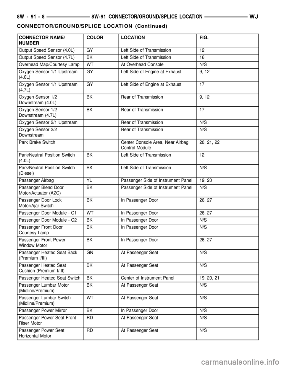
NUMBERCOLOR LOCATION FIG.
Output Speed Sensor (4.0L) GY Left Side of Transmission 12
Output Speed Sensor (4.7L) BK Left Side of Transmission 16
Overhead Map/Courtesy Lamp WT At Overhead Console N/S
Oxygen Sensor 1/1 Upstream
(4.0L)GY Left Side of Engine at Exhaust 9, 12
Oxygen Sensor 1/1 Upstream
(4.7L)GY Left Side of Engine at Exhaust 17
Oxygen Sensor 1/2
Downstream (4.0L)BK Rear of Transmission 9, 12
Oxygen Sensor 1/2
Downstream (4.7L)BK Rear of Transmission 17
Oxygen Sensor 2/1 Upstream Rear of Transmission N/S
Oxygen Sensor 2/2
DownstreamRear of Transmission N/S
Park Brake Switch Center Console Area, Near Airbag
Control Module20, 21, 22
Park/Neutral Position Switch
(4.0L)BK Left Side of Transmission 12
Park/Neutral Position Switch
(Diesel)BK Left Side of Transmission N/S
Passenger Airbag YL Passenger Side of Instrument Panel 19, 20
Passenger Blend Door
Motor/Actuator (AZC)BK Passenger Side of Instrument Panel N/S
Passenger Door Lock
Motor/Ajar SwitchBK In Passenger Door 26, 27
Passenger Door Module - C1 WT In Passenger Door 26, 27
Passenger Door Module - C2 BK In Passenger Door N/S
Passenger Front Door
Courtesy LampBK In Passenger Door N/S
Passenger Front Power
Window MotorBK In Passenger Door 26, 27
Passenger Heated Seat Back
(Premium I/III)GN At Passenger Seat N/S
Passenger Heated Seat
Cushion (Premium I/III)BK At Passenger Seat N/S
Passenger Heated Seat Switch BK Center of Instrument Panel 19, 20, 21
Passenger Lumbar Motor
(Midline/Premium)BK At Passenger Seat N/S
Passenger Lumbar Switch
(Midline/Premium)WT At Passenger Seat N/S
Passenger Power Mirror BK In Passenger Door N/S
Passenger Power Seat Front
Riser MotorRD At Passenger Seat N/S
Passenger Power Seat
Horizontal MotorRD At Passenger Seat N/S
8W - 91 - 8 8W-91 CONNECTOR/GROUND/SPLICE LOCATIONWJ
CONNECTOR/GROUND/SPLICE LOCATION (Continued)
Page 1184 of 2199
CONNECTOR NAME/
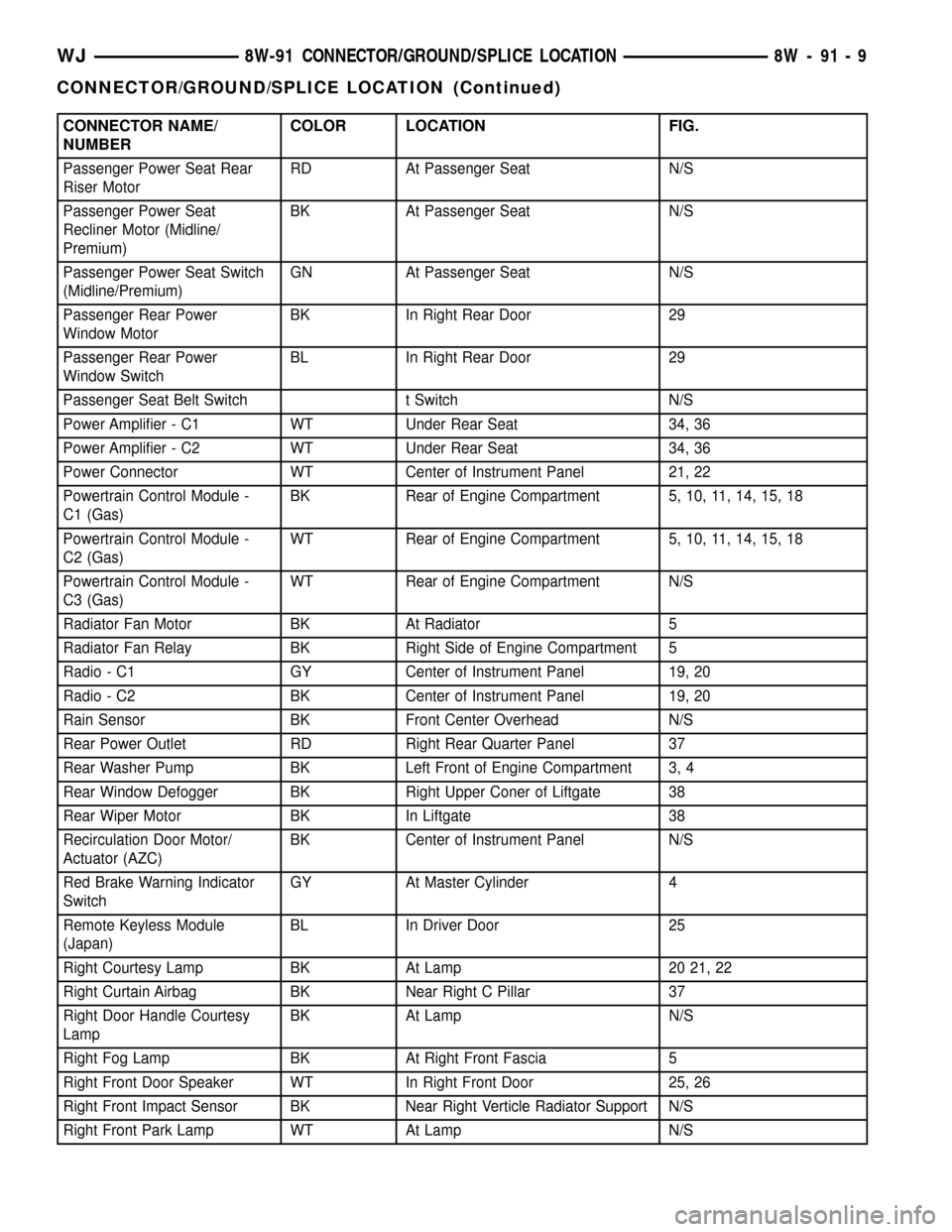
NUMBERCOLOR LOCATION FIG.
Passenger Power Seat Rear
Riser MotorRD At Passenger Seat N/S
Passenger Power Seat
Recliner Motor (Midline/
Premium)BK At Passenger Seat N/S
Passenger Power Seat Switch
(Midline/Premium)GN At Passenger Seat N/S
Passenger Rear Power
Window MotorBK In Right Rear Door 29
Passenger Rear Power
Window SwitchBL In Right Rear Door 29
Passenger Seat Belt Switch t Switch N/S
Power Amplifier - C1 WT Under Rear Seat 34, 36
Power Amplifier - C2 WT Under Rear Seat 34, 36
Power Connector WT Center of Instrument Panel 21, 22
Powertrain Control Module -
C1 (Gas)BK Rear of Engine Compartment 5, 10, 11, 14, 15, 18
Powertrain Control Module -
C2 (Gas)WT Rear of Engine Compartment 5, 10, 11, 14, 15, 18
Powertrain Control Module -
C3 (Gas)WT Rear of Engine Compartment N/S
Radiator Fan Motor BK At Radiator 5
Radiator Fan Relay BK Right Side of Engine Compartment 5
Radio - C1 GY Center of Instrument Panel 19, 20
Radio - C2 BK Center of Instrument Panel 19, 20
Rain Sensor BK Front Center Overhead N/S
Rear Power Outlet RD Right Rear Quarter Panel 37
Rear Washer Pump BK Left Front of Engine Compartment 3, 4
Rear Window Defogger BK Right Upper Coner of Liftgate 38
Rear Wiper Motor BK In Liftgate 38
Recirculation Door Motor/
Actuator (AZC)BK Center of Instrument Panel N/S
Red Brake Warning Indicator
SwitchGY At Master Cylinder 4
Remote Keyless Module
(Japan)BL In Driver Door 25
Right Courtesy Lamp BK At Lamp 20 21, 22
Right Curtain Airbag BK Near Right C Pillar 37
Right Door Handle Courtesy
LampBK At Lamp N/S
Right Fog Lamp BK At Right Front Fascia 5
Right Front Door Speaker WT In Right Front Door 25, 26
Right Front Impact Sensor BK Near Right Verticle Radiator Support N/S
Right Front Park Lamp WT At Lamp N/S
WJ8W-91 CONNECTOR/GROUND/SPLICE LOCATION 8W - 91 - 9
CONNECTOR/GROUND/SPLICE LOCATION (Continued)
Page 1186 of 2199
CONNECTOR NAME/
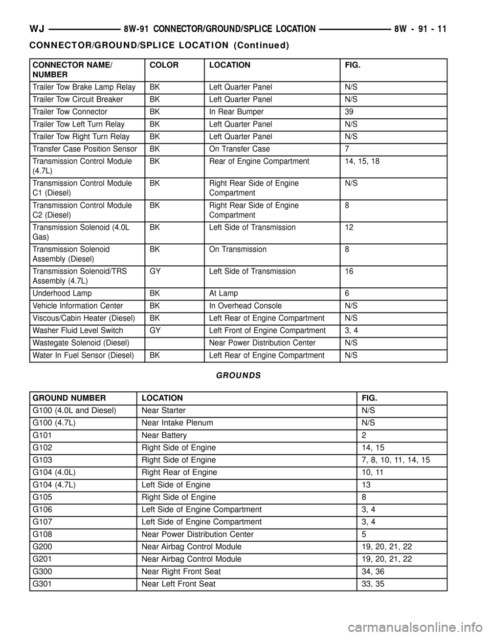
NUMBERCOLOR LOCATION FIG.
Trailer Tow Brake Lamp Relay BK Left Quarter Panel N/S
Trailer Tow Circuit Breaker BK Left Quarter Panel N/S
Trailer Tow Connector BK In Rear Bumper 39
Trailer Tow Left Turn Relay BK Left Quarter Panel N/S
Trailer Tow Right Turn Relay BK Left Quarter Panel N/S
Transfer Case Position Sensor BK On Transfer Case 7
Transmission Control Module
(4.7L)BK Rear of Engine Compartment 14, 15, 18
Transmission Control Module
C1 (Diesel)BK Right Rear Side of Engine
CompartmentN/S
Transmission Control Module
C2 (Diesel)BK Right Rear Side of Engine
Compartment8
Transmission Solenoid (4.0L
Gas)BK Left Side of Transmission 12
Transmission Solenoid
Assembly (Diesel)BK On Transmission 8
Transmission Solenoid/TRS
Assembly (4.7L)GY Left Side of Transmission 16
Underhood Lamp BK At Lamp 6
Vehicle Information Center BK In Overhead Console N/S
Viscous/Cabin Heater (Diesel) BK Left Rear of Engine Compartment N/S
Washer Fluid Level Switch GY Left Front of Engine Compartment 3, 4
Wastegate Solenoid (Diesel) Near Power Distribution Center N/S
Water In Fuel Sensor (Diesel) BK Left Rear of Engine Compartment N/S
GROUNDS
GROUND NUMBER LOCATION FIG.
G100 (4.0L and Diesel) Near Starter N/S
G100 (4.7L) Near Intake Plenum N/S
G101 Near Battery 2
G102 Right Side of Engine 14, 15
G103 Right Side of Engine 7, 8, 10, 11, 14, 15
G104 (4.0L) Right Rear of Engine 10, 11
G104 (4.7L) Left Side of Engine 13
G105 Right Side of Engine 8
G106 Left Side of Engine Compartment 3, 4
G107 Left Side of Engine Compartment 3, 4
G108 Near Power Distribution Center 5
G200 Near Airbag Control Module 19, 20, 21, 22
G201 Near Airbag Control Module 19, 20, 21, 22
G300 Near Right Front Seat 34, 36
G301 Near Left Front Seat 33, 35
WJ8W-91 CONNECTOR/GROUND/SPLICE LOCATION 8W - 91 - 11
CONNECTOR/GROUND/SPLICE LOCATION (Continued)
Page 1189 of 2199
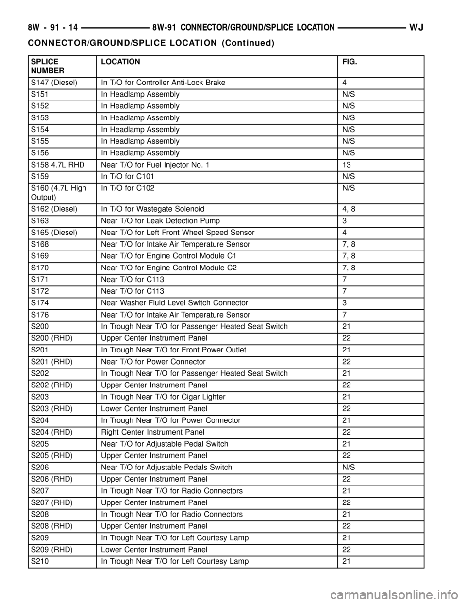
SPLICE
NUMBERLOCATION FIG.
S147 (Diesel) In T/O for Controller Anti-Lock Brake 4
S151 In Headlamp Assembly N/S
S152 In Headlamp Assembly N/S
S153 In Headlamp Assembly N/S
S154 In Headlamp Assembly N/S
S155 In Headlamp Assembly N/S
S156 In Headlamp Assembly N/S
S158 4.7L RHD Near T/O for Fuel Injector No. 1 13
S159 In T/O for C101 N/S
S160 (4.7L High
Output)In T/O for C102 N/S
S162 (Diesel) In T/O for Wastegate Solenoid 4, 8
S163 Near T/O for Leak Detection Pump 3
S165 (Diesel) Near T/O for Left Front Wheel Speed Sensor 4
S168 Near T/O for Intake Air Temperature Sensor 7, 8
S169 Near T/O for Engine Control Module C1 7, 8
S170 Near T/O for Engine Control Module C2 7, 8
S171 Near T/O for C113 7
S172 Near T/O for C113 7
S174 Near Washer Fluid Level Switch Connector 3
S176 Near T/O for Intake Air Temperature Sensor 7
S200 In Trough Near T/O for Passenger Heated Seat Switch 21
S200 (RHD) Upper Center Instrument Panel 22
S201 In Trough Near T/O for Front Power Outlet 21
S201 (RHD) Near T/O for Power Connector 22
S202 In Trough Near T/O for Passenger Heated Seat Switch 21
S202 (RHD) Upper Center Instrument Panel 22
S203 In Trough Near T/O for Cigar Lighter 21
S203 (RHD) Lower Center Instrument Panel 22
S204 In Trough Near T/O for Power Connector 21
S204 (RHD) Right Center Instrument Panel 22
S205 Near T/O for Adjustable Pedal Switch 21
S205 (RHD) Upper Center Instrument Panel 22
S206 Near T/O for Adjustable Pedals Switch N/S
S206 (RHD) Upper Center Instrument Panel 22
S207 In Trough Near T/O for Radio Connectors 21
S207 (RHD) Upper Center Instrument Panel 22
S208 In Trough Near T/O for Radio Connectors 21
S208 (RHD) Upper Center Instrument Panel 22
S209 In Trough Near T/O for Left Courtesy Lamp 21
S209 (RHD) Lower Center Instrument Panel 22
S210 In Trough Near T/O for Left Courtesy Lamp 21
8W - 91 - 14 8W-91 CONNECTOR/GROUND/SPLICE LOCATIONWJ
CONNECTOR/GROUND/SPLICE LOCATION (Continued)
Page 1190 of 2199
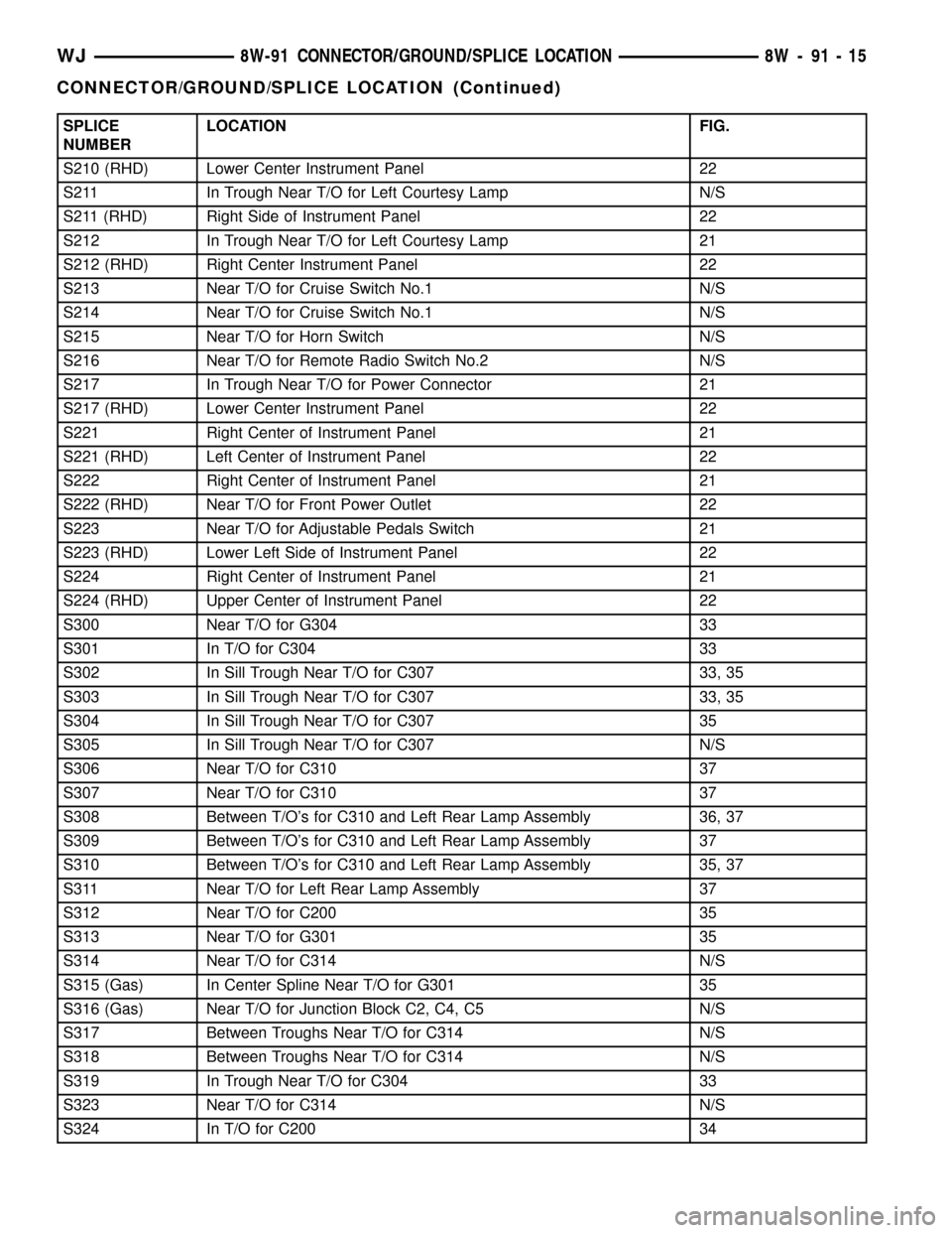
SPLICE
NUMBERLOCATION FIG.
S210 (RHD) Lower Center Instrument Panel 22
S211 In Trough Near T/O for Left Courtesy Lamp N/S
S211 (RHD) Right Side of Instrument Panel 22
S212 In Trough Near T/O for Left Courtesy Lamp 21
S212 (RHD) Right Center Instrument Panel 22
S213 Near T/O for Cruise Switch No.1 N/S
S214 Near T/O for Cruise Switch No.1 N/S
S215 Near T/O for Horn Switch N/S
S216 Near T/O for Remote Radio Switch No.2 N/S
S217 In Trough Near T/O for Power Connector 21
S217 (RHD) Lower Center Instrument Panel 22
S221 Right Center of Instrument Panel 21
S221 (RHD) Left Center of Instrument Panel 22
S222 Right Center of Instrument Panel 21
S222 (RHD) Near T/O for Front Power Outlet 22
S223 Near T/O for Adjustable Pedals Switch 21
S223 (RHD) Lower Left Side of Instrument Panel 22
S224 Right Center of Instrument Panel 21
S224 (RHD) Upper Center of Instrument Panel 22
S300 Near T/O for G304 33
S301 In T/O for C304 33
S302 In Sill Trough Near T/O for C307 33, 35
S303 In Sill Trough Near T/O for C307 33, 35
S304 In Sill Trough Near T/O for C307 35
S305 In Sill Trough Near T/O for C307 N/S
S306 Near T/O for C310 37
S307 Near T/O for C310 37
S308 Between T/O's for C310 and Left Rear Lamp Assembly 36, 37
S309 Between T/O's for C310 and Left Rear Lamp Assembly 37
S310 Between T/O's for C310 and Left Rear Lamp Assembly 35, 37
S311 Near T/O for Left Rear Lamp Assembly 37
S312 Near T/O for C200 35
S313 Near T/O for G301 35
S314 Near T/O for C314 N/S
S315 (Gas) In Center Spline Near T/O for G301 35
S316 (Gas) Near T/O for Junction Block C2, C4, C5 N/S
S317 Between Troughs Near T/O for C314 N/S
S318 Between Troughs Near T/O for C314 N/S
S319 In Trough Near T/O for C304 33
S323 Near T/O for C314 N/S
S324 In T/O for C200 34
WJ8W-91 CONNECTOR/GROUND/SPLICE LOCATION 8W - 91 - 15
CONNECTOR/GROUND/SPLICE LOCATION (Continued)
Page 1191 of 2199
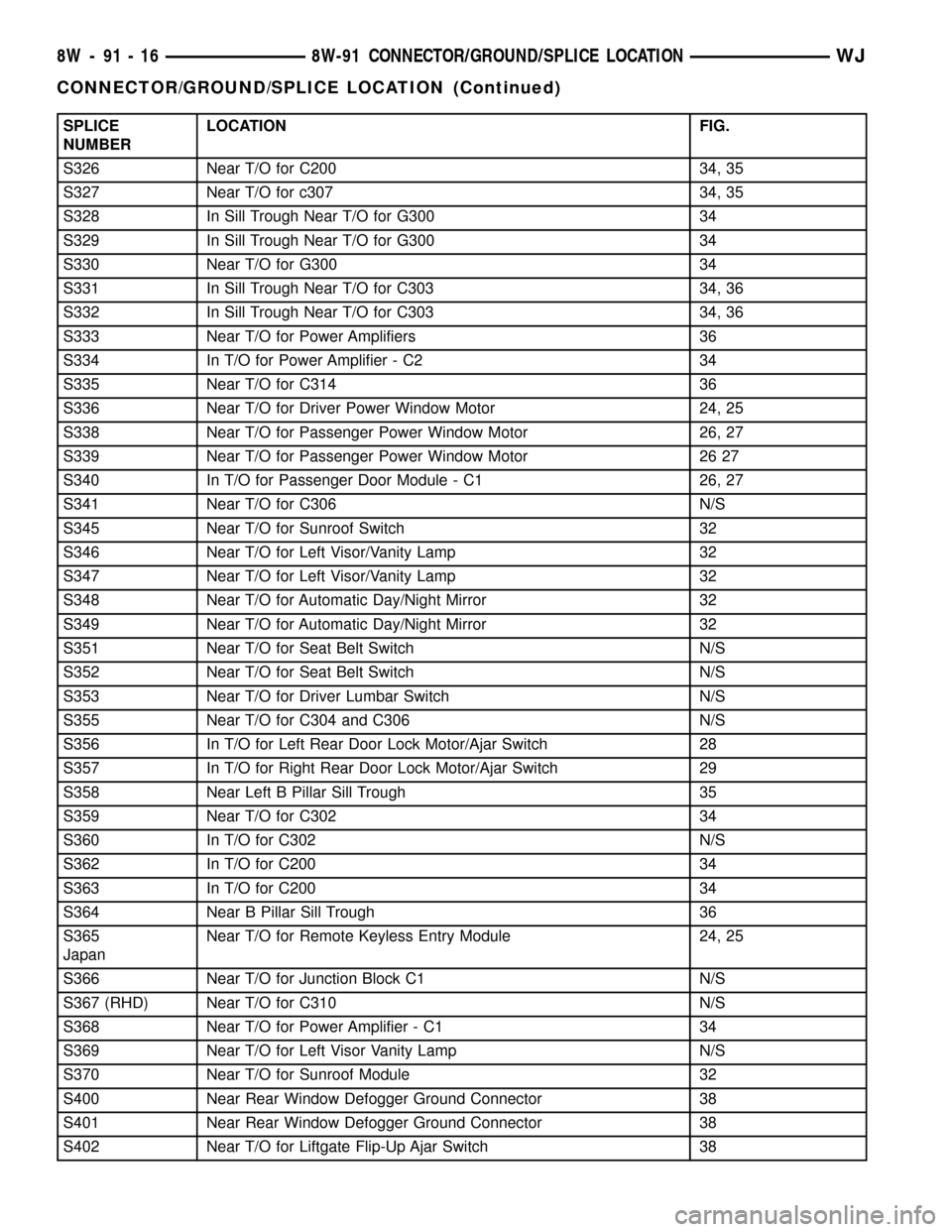
SPLICE
NUMBERLOCATION FIG.
S326 Near T/O for C200 34, 35
S327 Near T/O for c307 34, 35
S328 In Sill Trough Near T/O for G300 34
S329 In Sill Trough Near T/O for G300 34
S330 Near T/O for G300 34
S331 In Sill Trough Near T/O for C303 34, 36
S332 In Sill Trough Near T/O for C303 34, 36
S333 Near T/O for Power Amplifiers 36
S334 In T/O for Power Amplifier - C2 34
S335 Near T/O for C314 36
S336 Near T/O for Driver Power Window Motor 24, 25
S338 Near T/O for Passenger Power Window Motor 26, 27
S339 Near T/O for Passenger Power Window Motor 26 27
S340 In T/O for Passenger Door Module - C1 26, 27
S341 Near T/O for C306 N/S
S345 Near T/O for Sunroof Switch 32
S346 Near T/O for Left Visor/Vanity Lamp 32
S347 Near T/O for Left Visor/Vanity Lamp 32
S348 Near T/O for Automatic Day/Night Mirror 32
S349 Near T/O for Automatic Day/Night Mirror 32
S351 Near T/O for Seat Belt Switch N/S
S352 Near T/O for Seat Belt Switch N/S
S353 Near T/O for Driver Lumbar Switch N/S
S355 Near T/O for C304 and C306 N/S
S356 In T/O for Left Rear Door Lock Motor/Ajar Switch 28
S357 In T/O for Right Rear Door Lock Motor/Ajar Switch 29
S358 Near Left B Pillar Sill Trough 35
S359 Near T/O for C302 34
S360 In T/O for C302 N/S
S362 In T/O for C200 34
S363 In T/O for C200 34
S364 Near B Pillar Sill Trough 36
S365
JapanNear T/O for Remote Keyless Entry Module 24, 25
S366 Near T/O for Junction Block C1 N/S
S367 (RHD) Near T/O for C310 N/S
S368 Near T/O for Power Amplifier - C1 34
S369 Near T/O for Left Visor Vanity Lamp N/S
S370 Near T/O for Sunroof Module 32
S400 Near Rear Window Defogger Ground Connector 38
S401 Near Rear Window Defogger Ground Connector 38
S402 Near T/O for Liftgate Flip-Up Ajar Switch 38
8W - 91 - 16 8W-91 CONNECTOR/GROUND/SPLICE LOCATIONWJ
CONNECTOR/GROUND/SPLICE LOCATION (Continued)
Page 1229 of 2199

of the preparation procedures performed just prior to
new vehicle delivery.
The PDC has a molded plastic cover that can be
removed to provide service access to all of the fuses
and relays in the PDC. An integral latch and hinges
are molded into the PDC cover for easy removal. A
fuse layout map is integral to the underside of the
PDC cover to ensure proper fuse and relay identifica-
tion. The IOD fuse is a 50 ampere maxi-type car-
tridge fuse and, when removed, it is stored in a spare
fuse cavity within the PDC.
OPERATION
The term ignition-off draw identifies a normal con-
dition where power is being drained from the battery
with the ignition switch in the Off position. The IOD
fuse feeds the memory and sleep mode functions for
some of the electronic modules in the vehicle as well
as various other accessories that require battery cur-
rent when the ignition switch is in the Off position,
including the clock. The only reason the IOD fuse is
removed is to reduce the normal IOD of the vehicle
electrical system during new vehicle transportation
and pre-delivery storage to reduce battery depletion,
while still allowing vehicle operation so that the
vehicle can be loaded, unloaded and moved as needed
by both vehicle transportation company and dealer
personnel.
The IOD fuse is removed from PDC fuse cavity 15
when the vehicle is shipped from the assembly plant.
Dealer personnel must install the IOD fuse when the
vehicle is being prepared for delivery in order to
restore full electrical system operation. Once the
vehicle is prepared for delivery, the IOD function of
this fuse becomes transparent and the fuse that has
been assigned the IOD designation becomes only
another Fused B(+) circuit fuse. The IOD fuse serves
no useful purpose to the dealer technician in the ser-
vice or diagnosis of any vehicle system or condition,
other than the same purpose as that of any other
standard circuit protection device.
The IOD fuse can be used by the vehicle owner as
a convenient means of reducing battery depletion
when a vehicle is to be stored for periods not toexceed about thirty days. However, it must be
remembered that removing the IOD fuse will not
eliminate IOD, but only reduce this normal condition.
If a vehicle will be stored for more than about thirty
days, the battery negative cable should be discon-
nected to eliminate normal IOD; and, the battery
should be tested and recharged at regular intervals
during the vehicle storage period to prevent the bat-
tery from becoming discharged or damaged. Refer to
Battery Systemfor additional service information.
REMOVAL
The Ignition-Off Draw (IOD) fuses normal installa-
tion location is cavity 15 in the power distribution
center. When the vehicle is shipped from the assem-
bly plant the fuse is removed to maintain proper bat-
tery voltage during vehicle storage (in some cases).
Dealer personnel must install the IOD fuse when the
vehicle is being prepared for customer delivery in
order to restore full electrical system operation.
(1) Turn the ignition switch to the Off position.
(2) Unlatch and open the cover of the power distri-
bution center.
(3) Remove the IOD fuse from fusecavity 15of
the power distribution center (Fig. 2).
(4) Store the removed IOD fuse by installing it in
the unused fuse storagecavity 11of the PDC (Fig.
2).
(5) Close and latch the power distribution center
cover.
INSTALLATION
(1) Be certain the ignition switch is in the Off posi-
tion.
(2) Unlatch and open the cover of the power distri-
bution center.
(3) Remove the stored IOD fuse from fuse storage
cavity 11of the power distribution center.
(4) Use a thumb to press the IOD fuse firmly down
into power distribution center fusecavity 15.
(5) Close and latch the power distribution center
cover.
8W - 97 - 4 8W-97 POWER DISTRIBUTIONWJ
IOD FUSE (Continued)
Page 1230 of 2199

JUNCTION BLOCK
DESCRIPTION
An electrical Junction Block (JB) is concealed
beneath the driver side of the instrument panel in
the passenger compartment of the vehicle (Fig. 3).
The JB combines the functions previously provided
by a separate fuseblock module and relay center. The
JB serves to simplify and centralize numerous elec-
trical components, as well as to distribute electrical
current to many of the accessory systems in the vehi-
cle. It also eliminates the need for numerous splice
connections. The JB houses up to thirty-three blade-
type mini fuses, up to two blade-type automatic
resetting circuit breakers, the electronic combination
flasher, the Daytime Running Lamp (DRL) module
(Canada only) and up to twelve International Stan-
dards Organization (ISO) relays (three standard-type
and nine micro-type). The JB also incorporates an
integral connector and mounting for the Body Con-
trol Module (BCM). The BCM is secured with four
screws directly to the dash panel side of the JB.
Refer toBody Control Modulein Electronic Con-
trol Modules for additional information covering the
BCM.
The molded plastic JB housing has integral mounts
that are secured with two screws and two snap
retainers to the instrument panel steering column
support bracket behind the instrument panel steer-ing column opening cover. The JB is concealed above
the molded plastic instrument panel fuse cover. Inte-
gral latches molded into the fuse cover secure it the
JB, the BCM and the 16-way data link connector tab
of the instrument panel steering column support
bracket. The fuse cover can be pulled downward to
disengage the latches and provide service access to
all of the fuses, relays and wire harness connectors of
the JB. The fuse cover has a fuse puller and spare
fuses secured to its upper surface. Refer toInstru-
ment Panel Fuse Coverin Body for additional ser-
vice information.
The JB unit cannot be repaired and is only ser-
viced as an assembly. If any internal circuit or the JB
housing is faulty or damaged, the entire JB unit
must be replaced. The BCM is available for separate
service replacement.
OPERATION
All of the circuits entering and leaving the Junc-
tion Block (JB) do so through up to five wire harness
connectors, which are connected to the JB through
integral connector receptacles molded into the JB
housing. Internal connection of all of the JB circuits
is accomplished by a printed circuit board. There are
also two separate wire harness connections to con-
nector receptacles that are integral to the BCM.
Refer toJunction Blockin Wiring Diagrams for
additional information and the location of complete
JB circuit diagrams.
REMOVAL
WARNING: DISABLE THE AIRBAG SYSTEM
BEFORE ATTEMPTING ANY STEERING WHEEL,
STEERING COLUMN, OR INSTRUMENT PANEL
COMPONENT DIAGNOSIS OR SERVICE. DISCON-
NECT AND ISOLATE THE BATTERY NEGATIVE
(GROUND) CABLE, THEN WAIT TWO MINUTES FOR
THE AIRBAG SYSTEM CAPACITOR TO DISCHARGE
BEFORE PERFORMING FURTHER DIAGNOSIS OR
SERVICE. THIS IS THE ONLY SURE WAY TO DIS-
ABLE THE AIRBAG SYSTEM. FAILURE TO TAKE
THE PROPER PRECAUTIONS COULD RESULT IN
ACCIDENTAL AIRBAG DEPLOYMENT AND POSSI-
BLE PERSONAL INJURY.
(1) Disconnect and isolate the battery negative
cable.
(2) Remove the fuse cover from the bottom of the
Junction Block (JB).
(3) Remove the steering column opening cover
from the instrument panel. Refer toSteering Col-
umn Opening Coverin Body for the location of
steering column opening cover removal procedures.
Fig. 3 Junction Block Location
1 - REAR LATCHES
2 - JUNCTION BLOCK AND BODY CONTROL MODULE UNIT
3 - INSTRUMENT PANEL FUSE COVER
4 - SIDE LATCH
5 - FRONT LATCHES
WJ8W-97 POWER DISTRIBUTION 8W - 97 - 5
Page 1232 of 2199

(5) Reconnect the right and left body wire harness
bulkhead connectors to the connector receptacles
located near the center of the JB.
(6) Install and tighten the screws that secure the
right and left body wire harness bulkhead connectors
to the connector receptacles located near the center
of the JB. Tighten the screws to 2.2 N´m (20 in. lbs.).
(7) Reconnect the fused B(+) and the IOD wire
harness connectors to the connector receptacles
located near the bottom of the JB.
(8) Reach behind the JB to reconnect the instru-
ment panel wire harness bulkhead connector to the
connector receptacle located near the top of the JB.
(9) Install and tighten the screw that secures the
instrument panel wire harness bulkhead connector to
the connector receptacle located near the top of the
JB. Tighten the screw to 2.2 N´m (20 in. lbs.).
(10)
Reach behind the JB to reconnect the two
instrument panel wire harness connectors to the BCM
connector receptacles located near the bottom of the JB.
(11) Install the steering column opening cover onto
the instrument panel. Refer toSteering Column
Opening Coverin Body for the location of the steer-
ing column opening cover installation procedures.
(12)
Install the fuse cover onto the bottom of the JB.
(13) Reconnect the battery negative cable.
POWER DISTRIBUTION
CENTER
DESCRIPTION
All of the electrical current distributed throughout
this vehicle is directed through the standard equip-ment Power Distribution Center (PDC) (Fig. 7). The
molded plastic PDC housing is located in the right
front corner of the engine compartment, between the
battery and the right front inner fender shield. The
PDC houses up to fifteen maxi-type cartridge fuses,
which replace all in-line fusible links. The PDC also
houses up to thirteen blade-type mini fuses, and up
to ten International Standards Organization (ISO)
relays (two standard-type and eight micro-type).
The PDC housing is secured in the engine compart-
ment at three points. Integral mounts on both sides of
the PDC housing engage and latch to stanchions that
are integral to the molded plastic battery support. The
PDC is integral to the right headlamp and dash wire
harness, which exits from the bottom of the PDC hous-
ing. The PDC housing has a molded plastic cover that
includes two integral latches at the front and pivot
hooks at the back that snap over a hinge pin on the
rear of the PDC housing. The PDC cover is easily
opened or removed for service access and has a conve-
nient fuse and relay layout map integral to the inside
surface of the cover to ensure proper component identi-
fication. A fuse puller is also stored on the inside of the
PDC cover.
The PDC cover, the PDC housing lower cover, the
PDC relay wedges, the PDC relay cassettes and the
PDC B(+) terminal stud module are available for ser-
vice replacement. The PDC main housing unit, the
fuse wedges and the bus bars cannot be repaired and
Fig. 6 Junction Block
1 - SCREW (2)
2 - DRIVER SIDE COURTESY LAMP
3 - JUNCTION BLOCK
4 - 16 WAY DATA LINK CONNECTOR
Fig. 7 Power Distribution Center Location
1 - RIGHT FENDER
2 - BATTERY
3 - POWER DISTRIBUTION CENTER
4 - COVER
WJ8W-97 POWER DISTRIBUTION 8W - 97 - 7
JUNCTION BLOCK (Continued)