Indicator JEEP GRAND CHEROKEE 2002 WJ / 2.G Workshop Manual
[x] Cancel search | Manufacturer: JEEP, Model Year: 2002, Model line: GRAND CHEROKEE, Model: JEEP GRAND CHEROKEE 2002 WJ / 2.GPages: 2199, PDF Size: 76.01 MB
Page 1337 of 2199
INTAKE/EXHAUST VALVES &
SEATS
DESCRIPTION
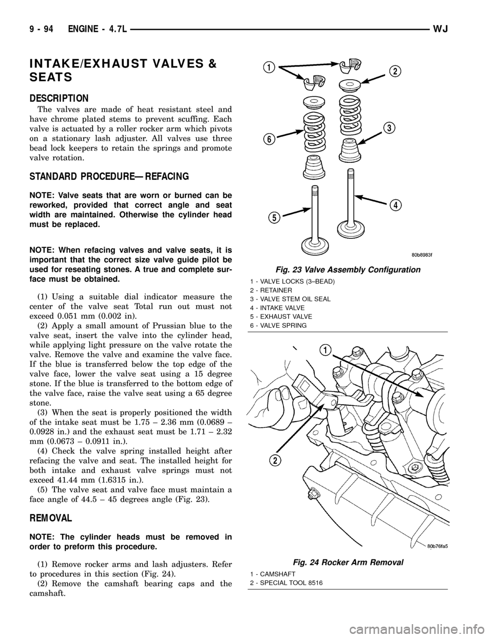
The valves are made of heat resistant steel and
have chrome plated stems to prevent scuffing. Each
valve is actuated by a roller rocker arm which pivots
on a stationary lash adjuster. All valves use three
bead lock keepers to retain the springs and promote
valve rotation.
STANDARD PROCEDUREÐREFACING
NOTE: Valve seats that are worn or burned can be
reworked, provided that correct angle and seat
width are maintained. Otherwise the cylinder head
must be replaced.
NOTE: When refacing valves and valve seats, it is
important that the correct size valve guide pilot be
used for reseating stones. A true and complete sur-
face must be obtained.
(1) Using a suitable dial indicator measure the
center of the valve seat Total run out must not
exceed 0.051 mm (0.002 in).
(2) Apply a small amount of Prussian blue to the
valve seat, insert the valve into the cylinder head,
while applying light pressure on the valve rotate the
valve. Remove the valve and examine the valve face.
If the blue is transferred below the top edge of the
valve face, lower the valve seat using a 15 degree
stone. If the blue is transferred to the bottom edge of
the valve face, raise the valve seat using a 65 degree
stone.
(3) When the seat is properly positioned the width
of the intake seat must be 1.75 ± 2.36 mm (0.0689 ±
0.0928 in.) and the exhaust seat must be 1.71 ± 2.32
mm (0.0673 ± 0.0911 in.).
(4) Check the valve spring installed height after
refacing the valve and seat. The installed height for
both intake and exhaust valve springs must not
exceed 41.44 mm (1.6315 in.).
(5) The valve seat and valve face must maintain a
face angle of 44.5 ± 45 degrees angle (Fig. 23).
REMOVAL
NOTE: The cylinder heads must be removed in
order to preform this procedure.
(1) Remove rocker arms and lash adjusters. Refer
to procedures in this section (Fig. 24).
(2) Remove the camshaft bearing caps and the
camshaft.
Fig. 23 Valve Assembly Configuration
1 - VALVE LOCKS (3±BEAD)
2 - RETAINER
3 - VALVE STEM OIL SEAL
4 - INTAKE VALVE
5 - EXHAUST VALVE
6 - VALVE SPRING
Fig. 24 Rocker Arm Removal
1 - CAMSHAFT
2 - SPECIAL TOOL 8516
9 - 94 ENGINE - 4.7LWJ
Page 1341 of 2199
VISUAL TEST METHOD
With the engine cool, remove the coolant pressure
cap. Start the engine and allow it to warm up until
thermostat opens.
If a large combustion/compression pressure leak
exists, bubbles will be visible in the coolant.
COOLING SYSTEM TESTER METHOD
WARNING: WITH COOLING SYSTEM TESTER IN
PLACE, PRESSURE WILL BUILD UP FAST. EXCES-
SIVE PRESSURE BUILT UP, BY CONTINUOUS
ENGINE OPERATION, MUST BE RELEASED TO A
SAFE PRESSURE POINT. NEVER PERMIT PRES-
SURE TO EXCEED 138 kPa (20 psi).
Install Cooling System Tester 7700 or equivalent to
pressure cap neck. Start the engine and observe the
tester's pressure gauge. If gauge pulsates with every
power stroke of a cylinder a combustion pressure
leak is evident.
CHEMICAL TEST METHOD
Combustion leaks into the cooling system can also
be checked by using Bloc-Chek Kit C-3685-A or
equivalent. Perform test following the procedures
supplied with the tool kit.
DIAGNOSIS AND TESTING - HYDRAULIC LASH
ADJUSTER
A tappet-like noise may be produced from several
items. Check the following items.
(1) Engine oil level too high or too low. This may
cause aerated oil to enter the adjusters and cause
them to be spongy.
(2) Insufficient running time after rebuilding cylin-
der head. Low speed running up to 1 hour may be
required.
(3) Turn engine off and let set for a few minutes
before restarting. Repeat this several times after
engine has reached normal operating temperature.
(4) Low oil pressure.
(5) The oil restrictor in cylinder head gasket or the
oil passage to the cylinder head is plugged with
debris.
(6) Air ingested into oil due to broken or cracked
oil pump pick up.
(7) Worn valve guides.
(8) Rocker arm ears contacting valve spring
retainer.
(9) Rocker arm loose, adjuster stuck or at maxi-
mum extension and still leaves lash in the system.
(10) Oil leak or excessive cam bore wear in cylin-
der head.
(11) Faulty lash adjuster.a. Check lash adjusters for sponginess while
installed in cylinder head and cam on camshaft at
base circle. Depress part of rocker arm over adjuster.
Normal adjusters should feel very firm. Spongy
adjusters can be bottomed out easily.
b. Remove suspected lash adjusters, and replace.
c. Before installation, make sure adjusters are at
least partially full of oil. This can be verified by little
or no plunger travel when lash adjuster is depressed.
REMOVAL
(1) Disconnect battery negitive cable.
(2) Raise the vehicle on a hoist.
(3) Disconnect the exhaust pipe at the right side
exhaust manifold.
(4) Drain the engine coolant (Refer to 7 - COOL-
ING - STANDARD PROCEDURE).
(5) Lower the vehicle.
(6) Remove the intake manifold (Refer to 9 -
ENGINE/MANIFOLDS/INTAKE MANIFOLD -
REMOVAL).
(7) Remove the cylinder head cover (Refer to 9 -
ENGINE/CYLINDER HEAD/CYLINDER HEAD
COVER(S) - REMOVAL).
(8) Remove oil fill housing from cylinder head.
(9) Remove accessory drive belt (Refer to 7 -
COOLING/ACCESSORY DRIVE/DRIVE BELTS -
REMOVAL).
(10) Rotate the crankshaft until the damper tim-
ing mark is aligned with TDC indicator mark (Fig.
9).
(11) Verify the V8 mark on the camshaft sprocket
is at the 12 o'clock position (Fig. 11). Rotate the
crankshaft one turn if necessary.
(12) Remove the crankshaft damper (Refer to 9 -
ENGINE/ENGINE BLOCK/VIBRATION DAMPER -
REMOVAL).
(13) Remove the timing chain cover (Refer to 9 -
ENGINE/VALVE TIMING/TIMING BELT / CHAIN
COVER(S) - REMOVAL).
(14) Lock the secondary timing chains to the idler
sprocket using Special Tool 8515 (Fig. 10).
NOTE: Mark the secondary timing chain prior to
removal to aid in installation.
(15) Mark the secondary timing chain, one link on
each side of the V8 mark on the camshaft drive gear
(Fig. 11).
(16) Remove the right side secondary chain ten-
sioner (Refer to 9 - ENGINE/VALVE TIMING/TIM-
ING BELT/CHAIN AND SPROCKETS - REMOVAL).
(17) Remove the cylinder head access plug (Fig.
29).
(18) Remove the right side secondary chain guide
(Refer to 9 - ENGINE/VALVE TIMING/TIMING
BELT/CHAIN AND SPROCKETS - REMOVAL).
9 - 98 ENGINE - 4.7LWJ
CYLINDER HEAD - RIGHT (Continued)
Page 1348 of 2199
STANDARD PROCEDUREÐREFACING
NOTE: Valve seats that are worn or burned can be
reworked, provided that correct angle and seat
width are maintained. Otherwise the cylinder head
must be replaced.
NOTE: When refacing valves and valve seats, it is
important that the correct size valve guide pilot be
used for reseating stones. A true and complete sur-
face must be obtained.
(1) Using a suitable dial indicator measure the
center of the valve seat Total run out must not
exceed 0.051 mm (0.002 in).
(2) Apply a small amount of Prussian blue to the
valve seat, insert the valve into the cylinder head,
while applying light pressure on the valve rotate the
valve. Remove the valve and examine the valve face.
If the blue is transferred below the top edge of the
valve face, lower the valve seat using a 15 degree
stone. If the blue is transferred to the bottom edge of
the valve face, raise the valve seat using a 65 degree
stone.
(3) When the seat is properly positioned the width
of the intake seat must be 1.75 ± 2.36 mm (0.0689 ±
0.0928 in.) and the exhaust seat must be 1.71 ± 2.32
mm (0.0673 ± 0.0911 in.).
(4) Check the valve spring installed height after
refacing the valve and seat. The installed height for
both intake and exhaust valve springs must not
exceed 41.44 mm (1.6315 in.).
(5) The valve seat and valve face must maintain a
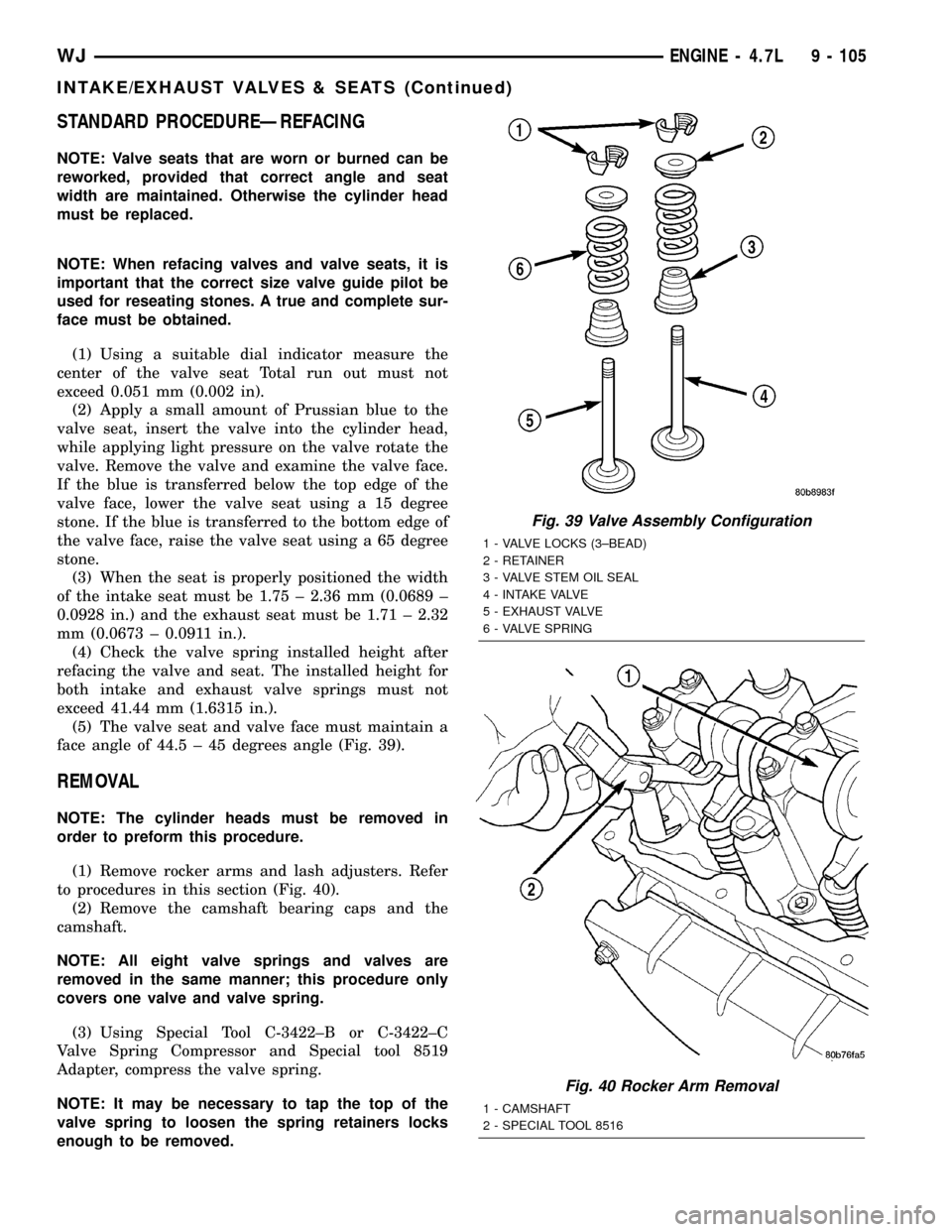
face angle of 44.5 ± 45 degrees angle (Fig. 39).
REMOVAL
NOTE: The cylinder heads must be removed in
order to preform this procedure.
(1) Remove rocker arms and lash adjusters. Refer
to procedures in this section (Fig. 40).
(2) Remove the camshaft bearing caps and the
camshaft.
NOTE: All eight valve springs and valves are
removed in the same manner; this procedure only
covers one valve and valve spring.
(3) Using Special Tool C-3422±B or C-3422±C
Valve Spring Compressor and Special tool 8519
Adapter, compress the valve spring.
NOTE: It may be necessary to tap the top of the
valve spring to loosen the spring retainers locks
enough to be removed.
Fig. 39 Valve Assembly Configuration
1 - VALVE LOCKS (3±BEAD)
2 - RETAINER
3 - VALVE STEM OIL SEAL
4 - INTAKE VALVE
5 - EXHAUST VALVE
6 - VALVE SPRING
Fig. 40 Rocker Arm Removal
1 - CAMSHAFT
2 - SPECIAL TOOL 8516
WJENGINE - 4.7L 9 - 105
INTAKE/EXHAUST VALVES & SEATS (Continued)
Page 1354 of 2199
Bearing
MarkSIZE USED WITH
JOURNAL SIZE
.025 US.025 mm 50.983-50.967 mm
(.001 in.) (2.0073-2.0066 in.)
Std.STANDARD 50.992-51.008 mm
(2.0076-2.0082 in.)
.250 US.250 mm 50.758-50.742 mm
(.010 in.) (1.9984-1.9978 in.)
(9) Repeat the Plastigage measurement to verify
your bearing selection prior to final assembly.
(10) Once you have selected the proper insert,
install the insert and cap. Tighten the connecting rod
bolts to 27 N´m (20 ft. lbs.) plus a 90É turn.
Slide snug-fitting feeler gauge between the con-
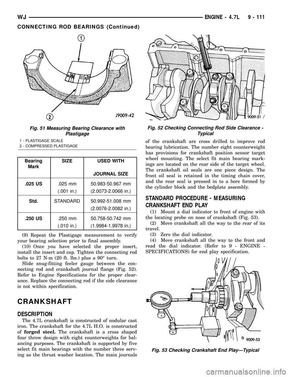
necting rod and crankshaft journal flange (Fig. 52).
Refer to Engine Specifications for the proper clear-
ance. Replace the connecting rod if the side clearance
is not within specification.
CRANKSHAFT
DESCRIPTION
The 4.7L crankshaft is constructed of nodular cast
iron. The crankshaft for the 4.7L H.O. is constructed
offorged steel.The crankshaft is a cross shaped
four throw design with eight counterweights for bal-
ancing purposes. The crankshaft is supported by five
select fit main bearings with the number three serv-
ing as the thrust washer location. The main journalsof the crankshaft are cross drilled to improve rod
bearing lubrication. The number eight counterweight
has provisions for crankshaft position sensor target
wheel mounting. The select fit main bearing mark-
ings are located on the rear side of the target wheel.
The crankshaft oil seals are one piece design. The
front oil seal is retained in the timing chain cover,
and the rear seal is pressed in to a bore formed by
the cylinder block and the bedplate assembly.
STANDARD PROCEDURE - MEASURING
CRANKSHAFT END PLAY
(1) Mount a dial indicator to front of engine with
the locating probe on nose of crankshaft (Fig. 53).
(2) Move crankshaft all the way to the rear of its
travel.
(3) Zero the dial indicator.
(4) Move crankshaft all the way to the front and
read the dial indicator. (Refer to 9 - ENGINE -
SPECIFICATIONS) for end play specification.
Fig. 51 Measuring Bearing Clearance with
Plastigage
1 - PLASTIGAGE SCALE
2 - COMPRESSED PLASTIGAGE
Fig. 52 Checking Connecting Rod Side Clearance -
Typical
Fig. 53 Checking Crankshaft End PlayÐTypical
WJENGINE - 4.7L 9 - 111
CONNECTING ROD BEARINGS (Continued)
Page 1373 of 2199
If the leakage occurs at the crankshaft rear oil seal
area:
(1) Disconnect the battery.
(2) Raise the vehicle.
(3) Remove torque converter or clutch housing
cover and inspect rear of block for evidence of oil.
Use a black light to check for the oil leak:
(a) Circular spray pattern generally indicates
seal leakage or crankshaft damage.
(b) Where leakage tends to run straight down,
possible causes are a porous block, distributor seal,
camshaft bore cup plugs oil galley pipe plugs, oil
filter runoff, and main bearing cap to cylinder
block mating surfaces.
(4) If no leaks are detected, pressurize the crank-
case as outlined in the, Inspection (Engine oil Leaks
in general)
CAUTION: Do not exceed 20.6 kPa (3 psi).
(5) If the leak is not detected, very slowly turn the
crankshaft and watch for leakage. If a leak is
detected between the crankshaft and seal while
slowly turning the crankshaft, it is possible the
crankshaft seal surface is damaged. The seal area on
the crankshaft could have minor nicks or scratches
that can be polished out with emery cloth.
CAUTION: Use extreme caution when crankshaft
polishing is necessary to remove minor nicks and
scratches. The crankshaft seal flange is especially
machined to complement the function of the rear oil
seal.
(6) For bubbles that remain steady with shaft
rotation, no further inspection can be done until dis-
assembled.
OIL
STANDARD PROCEDURE - ENGINE OIL
WARNING: NEW OR USED ENGINE OIL CAN BE
IRRITATING TO THE SKIN. AVOID PROLONGED OR
REPEATED SKIN CONTACT WITH ENGINE OIL.
CONTAMINANTS IN USED ENGINE OIL, CAUSED BY
INTERNAL COMBUSTION, CAN BE HAZARDOUS TO
YOUR HEALTH. THOROUGHLY WASH EXPOSED
SKIN WITH SOAP AND WATER. DO NOT WASH
SKIN WITH GASOLINE, DIESEL FUEL, THINNER, OR
SOLVENTS, HEALTH PROBLEMS CAN RESULT. DO
NOT POLLUTE, DISPOSE OF USED ENGINE OIL
PROPERLY.
ENGINE OIL SPECIFICATION
CAUTION: Do not use non-detergent or straight
mineral oil when adding or changing crankcase
lubricant. Engine failure can result.
API SERVICE GRADE CERTIFIED
Use an engine oil that is API Service Grade Certi-
fied. MOPARtprovides engine oils that conform to
this service grade.
SAE VISCOSITY
An SAE viscosity grade is used to specify the vis-
cosity of engine oil. Use only engine oils with multi-
ple viscosities such as 5W-30 or 10W-30 in the 4.7L
engines.The 4.7L H.O. uses 10W-30 oil only.These
are specified with a dual SAE viscosity grade which
indicates the cold-to-hot temperature viscosity range.
Select an engine oil that is best suited to your par-
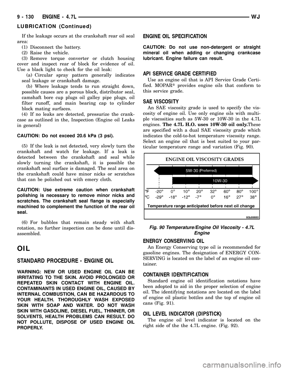
ticular temperature range and variation (Fig. 90).
ENERGY CONSERVING OIL
An Energy Conserving type oil is recommended for
gasoline engines. The designation of ENERGY CON-
SERVING is located on the label of an engine oil con-
tainer.
CONTAINER IDENTIFICATION
Standard engine oil identification notations have
been adopted to aid in the proper selection of engine
oil. The identifying notations are located on the label
of engine oil plastic bottles and the top of engine oil
cans (Fig. 91).
OIL LEVEL INDICATOR (DIPSTICK)
The engine oil level indicator is located on the
right side of the the 4.7L engine. (Fig. 92).
Fig. 90 Temperature/Engine Oil Viscosity - 4.7L
Engine
9 - 130 ENGINE - 4.7LWJ
LUBRICATION (Continued)
Page 1386 of 2199
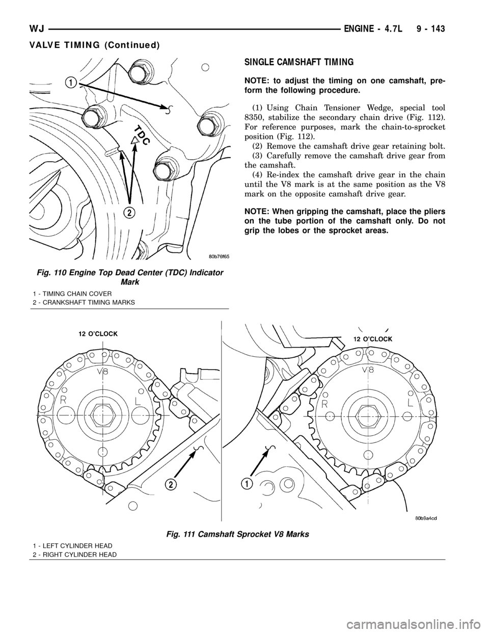
SINGLE CAMSHAFT TIMING
NOTE: to adjust the timing on one camshaft, pre-
form the following procedure.
(1) Using Chain Tensioner Wedge, special tool
8350, stabilize the secondary chain drive (Fig. 112).
For reference purposes, mark the chain-to-sprocket
position (Fig. 112).
(2) Remove the camshaft drive gear retaining bolt.
(3) Carefully remove the camshaft drive gear from
the camshaft.
(4) Re-index the camshaft drive gear in the chain
until the V8 mark is at the same position as the V8
mark on the opposite camshaft drive gear.
NOTE: When gripping the camshaft, place the pliers
on the tube portion of the camshaft only. Do not
grip the lobes or the sprocket areas.
Fig. 110 Engine Top Dead Center (TDC) Indicator
Mark
1 - TIMING CHAIN COVER
2 - CRANKSHAFT TIMING MARKS
Fig. 111 Camshaft Sprocket V8 Marks
1 - LEFT CYLINDER HEAD
2 - RIGHT CYLINDER HEAD
WJENGINE - 4.7L 9 - 143
VALVE TIMING (Continued)
Page 1390 of 2199
TIMING BELT/CHAIN AND
SPROCKETS
REMOVAL
(1) Disconnect negative cable from battery.
(2) Drain cooling system (Refer to 7 - COOLING -
STANDARD PROCEDURE).
(3) Remove right and left cylinder head covers
(Refer to 9 - ENGINE/CYLINDER HEAD/CYLIN-
DER HEAD COVER(S) - REMOVAL).
(4) Remove radiator fan (Refer to 7 - COOLING/
ENGINE/RADIATOR FAN - REMOVAL).
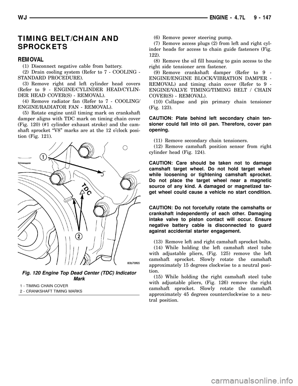
(5) Rotate engine until timing mark on crankshaft
damper aligns with TDC mark on timing chain cover
(Fig. 120) (#1 cylinder exhaust stroke) and the cam-
shaft sprocket ªV8º marks are at the 12 o'clock posi-
tion (Fig. 121).(6) Remove power steering pump.
(7) Remove access plugs (2) from left and right cyl-
inder heads for access to chain guide fasteners (Fig.
122).
(8) Remove the oil fill housing to gain access to the
right side tensioner arm fastener.
(9) Remove crankshaft damper (Refer to 9 -
ENGINE/ENGINE BLOCK/VIBRATION DAMPER -
REMOVAL) and timing chain cover (Refer to 9 -
ENGINE/VALVE TIMING/TIMING BELT / CHAIN
COVER(S) - REMOVAL).
(10) Collapse and pin primary chain tensioner
(Fig. 123).
CAUTION: Plate behind left secondary chain ten-
sioner could fall into oil pan. Therefore, cover pan
opening.
(11) Remove secondary chain tensioners.
(12) Remove camshaft position sensor from right
cylinder head (Fig. 124).
CAUTION: Care should be taken not to damage
camshaft target wheel. Do not hold target wheel
while loosening or tightening camshaft sprocket.
Do not place the target wheel near a magnetic
source of any kind. A damaged or magnetized tar-
get wheel could cause a vehicle no start condition.
CAUTION: Do not forcefully rotate the camshafts or
crankshaft independently of each other. Damaging
intake valve to piston contact will occur. Ensure
negative battery cable is disconnected to guard
against accidental starter engagement.
(13) Remove left and right camshaft sprocket bolts.
(14) While holding the left camshaft steel tube
with adjustable pliers, (Fig. 125) remove the left
camshaft sprocket. Slowly rotate the camshaft
approximately 15 degrees clockwise to a neutral posi-
tion.
(15) While holding the right camshaft steel tube
with adjustable pliers, (Fig. 126) remove the right
camshaft sprocket. Slowly rotate the camshaft
approximately 45 degrees counterclockwise to a neu-
tral position.
Fig. 120 Engine Top Dead Center (TDC) Indicator
Mark
1 - TIMING CHAIN COVER
2 - CRANKSHAFT TIMING MARKS
WJENGINE - 4.7L 9 - 147
Page 1396 of 2199
(22) Install timing chain cover (Refer to 9 -
ENGINE/VALVE TIMING/TIMING BELT / CHAIN
COVER(S) - INSTALLATION) and crankshaft
damper (Refer to 9 - ENGINE/ENGINE BLOCK/VI-
BRATION DAMPER - INSTALLATION).
(23) Install cylinder head covers (Refer to 9 -
ENGINE/CYLINDER HEAD/CYLINDER HEAD
COVER(S) - INSTALLATION).
NOTE: Before installing threaded plug in right cylin-
der head, the plug must be coated with sealant to
prevent leaks.
(24) Coat the large threaded access plug with
MopartThread Sealant with Teflon, then install
into the right cylinder head and tighten to 81 N´m
(60 ft. lbs.) (Fig. 122).
(25) Install the oil fill housing.
(26) Install access plug in left cylinder head (Fig.
122).
(27) Install power steering pump.
(28) Install radiator fan (Refer to 7 - COOLING/
ENGINE/RADIATOR FAN - INSTALLATION).
(29) Fill cooling system (Refer to 7 - COOLING -
STANDARD PROCEDURE).
(30) Connect negative cable to battery.
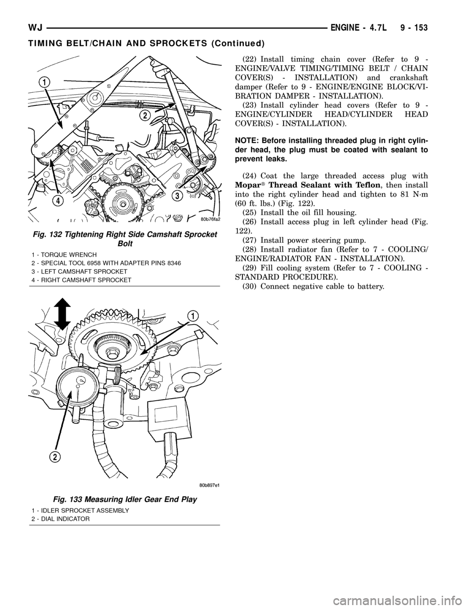
Fig. 132 Tightening Right Side Camshaft Sprocket
Bolt
1 - TORQUE WRENCH
2 - SPECIAL TOOL 6958 WITH ADAPTER PINS 8346
3 - LEFT CAMSHAFT SPROCKET
4 - RIGHT CAMSHAFT SPROCKET
Fig. 133 Measuring Idler Gear End Play
1 - IDLER SPROCKET ASSEMBLY
2 - DIAL INDICATOR
WJENGINE - 4.7L 9 - 153
TIMING BELT/CHAIN AND SPROCKETS (Continued)
Page 1470 of 2199
In Closed Loop operation, the PCM monitors cer-
tain O2 sensor input(s) along with other inputs, and
adjusts the injector pulse width accordingly. During
Open Loop operation, the PCM ignores the O2 sensor
input. The PCM adjusts injector pulse width based
on preprogrammed (fixed) values and inputs from
other sensors.
Upstream Sensor (Non-California Emissions):
The upstream sensor (1/1) provides an input voltage
to the PCM. The input tells the PCM the oxygen con-
tent of the exhaust gas. The PCM uses this informa-
tion to fine tune fuel delivery to maintain the correct
oxygen content at the downstream oxygen sensor.
The PCM will change the air/fuel ratio until the
upstream sensor inputs a voltage that the PCM has
determined will make the downstream sensor output
(oxygen content) correct.
The upstream oxygen sensor also provides an input
to determine catalytic convertor efficiency.
Downstream Sensor (Non-California Emis-
sions):The downstream oxygen sensor (1/2) is also
used to determine the correct air-fuel ratio. As the
oxygen content changes at the downstream sensor,
the PCM calculates how much air-fuel ratio change is
required. The PCM then looks at the upstream oxy-
gen sensor voltage and changes fuel delivery until
the upstream sensor voltage changes enough to cor-
rect the downstream sensor voltage (oxygen content).
The downstream oxygen sensor also provides an
input to determine catalytic convertor efficiency.
Upstream Sensors (California Engines):Tw o
upstream sensors are used (1/1 and 2/1). The 1/1 sen-
sor is the first sensor to receive exhaust gases from
the #1 cylinder. They provide an input voltage to the
PCM. The input tells the PCM the oxygen content of
the exhaust gas. The PCM uses this information to
fine tune fuel delivery to maintain the correct oxygen
content at the downstream oxygen sensors. The PCM
will change the air/fuel ratio until the upstream sen-
sors input a voltage that the PCM has determined
will make the downstream sensors output (oxygen
content) correct.
The upstream oxygen sensors also provide an input
to determine mini-catalyst efficiency. Main catalytic
convertor efficiency is not calculated with this pack-
age.
Downstream Sensors (California Engines):
Two downstream sensors are used (1/2 and 2/2). The
downstream sensors are used to determine the cor-
rect air-fuel ratio. As the oxygen content changes at
the downstream sensor, the PCM calculates how
much air-fuel ratio change is required. The PCM
then looks at the upstream oxygen sensor voltage,
and changes fuel delivery until the upstream sensor
voltage changes enough to correct the downstream
sensor voltage (oxygen content).The downstream oxygen sensors also provide an
input to determine mini-catalyst efficiency. Main cat-
alytic convertor efficiency is not calculated with this
package.
Engines equipped with either a downstream sen-
sor(s), or a post-catalytic sensor, will monitor cata-
lytic convertor efficiency. If efficiency is below
emission standards, the Malfunction Indicator Lamp
(MIL) will be illuminated and a Diagnostic Trouble
Code (DTC) will be set. Refer to Monitored Systems
in Emission Control Systems for additional informa-
tion.
REMOVAL
Never apply any type of grease to the oxygen
sensor electrical connector, or attempt any sol-
dering of the sensor wiring harness.
Oxygen sensor (O2S) locations are shown in (Fig.
33) and (Fig. 34).
WARNING: THE EXHAUST MANIFOLD, EXHAUST
PIPES AND CATALYTIC CONVERTER(S) BECOME
VERY HOT DURING ENGINE OPERATION. ALLOW
ENGINE TO COOL BEFORE REMOVING OXYGEN
SENSOR.
(1) Raise and support vehicle.
(2) Disconnect O2S pigtail harness from main wir-
ing harness.
(3) If equipped, disconnect sensor wire harness
mounting clips from engine or body.
CAUTION: When disconnecting sensor electrical
connector, do not pull directly on wire going into
sensor.
(4) Remove O2S sensor with an oxygen sensor
removal and installation tool.
INSTALLATION
Threads of new oxygen sensors are factory coated
with anti-seize compound to aid in removal.DO
NOT add any additional anti-seize compound to
threads of a new oxygen sensor.
(1) Install O2S sensor. Tighten to 30 N´m (22 ft.
lbs.) torque.
(2) Connect O2S sensor wire connector to main
wiring harness.
(3) If equipped, connect sensor wire harness
mounting clips to engine or body.When Equipped:
The O2S pigtail harness must be clipped and/or
bolted back to their original positions on
engine or body to prevent mechanical damage
to wiring..
(4) Lower vehicle.
WJFUEL INJECTION 14 - 51
O2S SENSOR (Continued)
Page 1548 of 2199
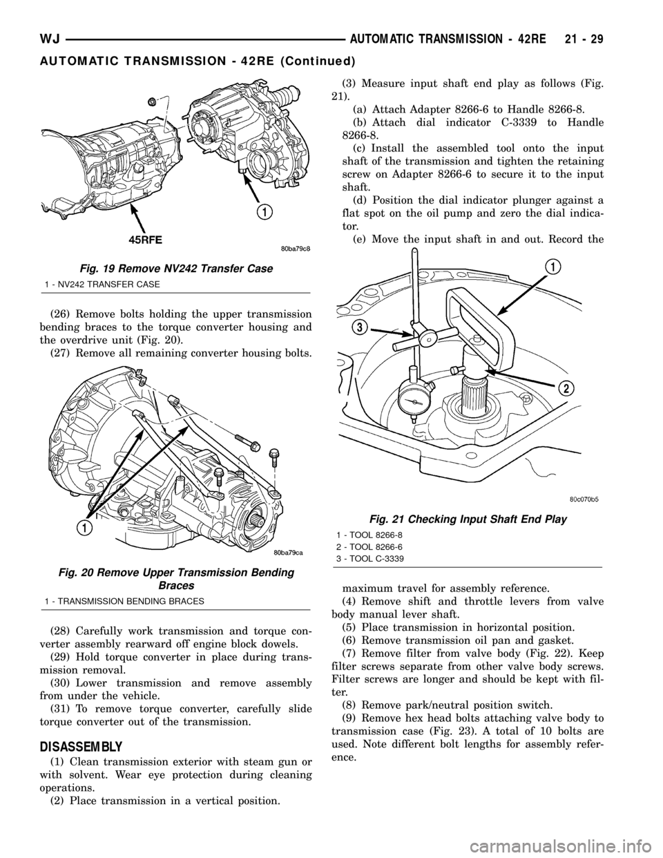
(26) Remove bolts holding the upper transmission
bending braces to the torque converter housing and
the overdrive unit (Fig. 20).
(27) Remove all remaining converter housing bolts.
(28) Carefully work transmission and torque con-
verter assembly rearward off engine block dowels.
(29) Hold torque converter in place during trans-
mission removal.
(30) Lower transmission and remove assembly
from under the vehicle.
(31) To remove torque converter, carefully slide
torque converter out of the transmission.
DISASSEMBLY
(1) Clean transmission exterior with steam gun or
with solvent. Wear eye protection during cleaning
operations.
(2) Place transmission in a vertical position.(3) Measure input shaft end play as follows (Fig.
21).
(a) Attach Adapter 8266-6 to Handle 8266-8.
(b) Attach dial indicator C-3339 to Handle
8266-8.
(c) Install the assembled tool onto the input
shaft of the transmission and tighten the retaining
screw on Adapter 8266-6 to secure it to the input
shaft.
(d) Position the dial indicator plunger against a
flat spot on the oil pump and zero the dial indica-
tor.
(e) Move the input shaft in and out. Record the
maximum travel for assembly reference.
(4) Remove shift and throttle levers from valve
body manual lever shaft.
(5) Place transmission in horizontal position.
(6) Remove transmission oil pan and gasket.
(7) Remove filter from valve body (Fig. 22). Keep
filter screws separate from other valve body screws.
Filter screws are longer and should be kept with fil-
ter.
(8) Remove park/neutral position switch.
(9) Remove hex head bolts attaching valve body to
transmission case (Fig. 23). A total of 10 bolts are
used. Note different bolt lengths for assembly refer-
ence.
Fig. 19 Remove NV242 Transfer Case
1 - NV242 TRANSFER CASE
Fig. 20 Remove Upper Transmission Bending
Braces
1 - TRANSMISSION BENDING BRACES
Fig. 21 Checking Input Shaft End Play
1 - TOOL 8266-8
2 - TOOL 8266-6
3 - TOOL C-3339
WJAUTOMATIC TRANSMISSION - 42RE 21 - 29
AUTOMATIC TRANSMISSION - 42RE (Continued)