seat JEEP GRAND CHEROKEE 2002 WJ / 2.G Workshop Manual
[x] Cancel search | Manufacturer: JEEP, Model Year: 2002, Model line: GRAND CHEROKEE, Model: JEEP GRAND CHEROKEE 2002 WJ / 2.GPages: 2199, PDF Size: 76.01 MB
Page 575 of 2199
SEAT BELT TURNING LOOP
ADJUSTER
REMOVAL
WARNING: DURING AND FOLLOWING ANY SEAT
BELT SERVICE, CAREFULLY INSPECT ALL SEAT
BELTS, BUCKLES, MOUNTING HARDWARE, AND
RETRACTORS FOR PROPER INSTALLATION,
OPERATION, OR DAMAGE. REPLACE ANY BELT
THAT IS CUT, FRAYED, OR TORN. STRAIGHTEN
ANY BELT THAT IS TWISTED. TIGHTEN ANY
LOOSE FASTENERS. REPLACE ANY BELT THAT
HAS A DAMAGED OR INOPERATIVE BUCKLE OR
RETRACTOR. REPLACE ANY BELT THAT HAS A
BENT OR DAMAGED LATCH PLATE OR ANCHOR
PLATE. NEVER ATTEMPT TO REPAIR A SEAT BELT
COMPONENT. ALWAYS REPLACE DAMAGED OR
FAULTY SEAT BELT COMPONENTS WITH THE COR-
RECT, NEW AND UNUSED REPLACEMENT PARTS
LISTED IN THE MOPAR PARTS CATALOG.
(1) Remove the turning loop from the front or rear
seat belt turning loop adjuster. (Refer to 8 - ELEC-
TRICAL/RESTRAINTS/FRONT SEAT BELT &
RETRACTOR - REMOVAL) or (Refer to 8 - ELEC-
TRICAL/RESTRAINTS/REAR OUTBOARD SEAT
BELT & RETRACTOR - REMOVAL).
(2) Remove the trim from the upper B-pillar (front
seat belt adjuster) or upper C-pillar (rear seat belt
adjuster). (Refer to 23 - BODY/INTERIOR/B-PILLAR
UPPER TRIM - REMOVAL) or (Refer to 23 - BODY/
INTERIOR/C-PILLAR TRIM - REMOVAL).
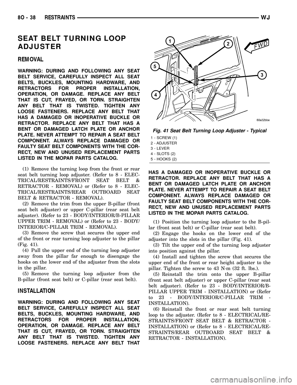
(3) Remove the screw that secures the upper end
of the front or rear turning loop adjuster to the pillar
(Fig. 41).
(4) Pull the upper end of the turning loop adjuster
away from the pillar far enough to disengage the
hooks on the lower end of the adjuster from the slots
in the pillar.
(5) Remove the turning loop adjuster from the
B-pillar (front seat belt) or C-pillar (rear seat belt).
INSTALLATION
WARNING: DURING AND FOLLOWING ANY SEAT
BELT SERVICE, CAREFULLY INSPECT ALL SEAT
BELTS, BUCKLES, MOUNTING HARDWARE, AND
RETRACTORS FOR PROPER INSTALLATION,
OPERATION, OR DAMAGE. REPLACE ANY BELT
THAT IS CUT, FRAYED, OR TORN. STRAIGHTEN
ANY BELT THAT IS TWISTED. TIGHTEN ANY
LOOSE FASTENERS. REPLACE ANY BELT THATHAS A DAMAGED OR INOPERATIVE BUCKLE OR
RETRACTOR. REPLACE ANY BELT THAT HAS A
BENT OR DAMAGED LATCH PLATE OR ANCHOR
PLATE. NEVER ATTEMPT TO REPAIR A SEAT BELT
COMPONENT. ALWAYS REPLACE DAMAGED OR
FAULTY SEAT BELT COMPONENTS WITH THE COR-
RECT, NEW AND UNUSED REPLACEMENT PARTS
LISTED IN THE MOPAR PARTS CATALOG.
(1) Position the turning loop adjuster to the B-pil-
lar (front seat belt) or C-pillar (rear seat belt).
(2) Engage the hooks on the lower end of the
adjuster into the slots in the pillar (Fig. 41).
(3) Tilt the upper end of the turning loop adjuster
into position against the pillar.
(4) Install and tighten the screw that secures the
upper end of the front or rear height adjuster to the
pillar. Tighten the screw to 43 N´m (32 ft. lbs.).
(5) Reinstall the trim onto the upper B-pillar
(front seat belt adjuster) or upper C-pillar (rear seat
belt adjuster). (Refer to 23 - BODY/INTERIOR/B-
PILLAR UPPER TRIM - INSTALLATION) or (Refer
to 23 - BODY/INTERIOR/C-PILLAR TRIM -
INSTALLATION).
(6) Reinstall the front or rear seat belt turning
loop to the adjuster. (Refer to 8 - ELECTRICAL/RE-
STRAINTS/FRONT SEAT BELT & RETRACTOR -
INSTALLATION) or (Refer to 8 - ELECTRICAL/RE-
STRAINTS/REAR OUTBOARD SEAT BELT &
RETRACTOR - INSTALLATION).
Fig. 41 Seat Belt Turning Loop Adjuster - Typical
1 - SCREW (1)
2 - ADJUSTER
3 - LEVER
4 - SLOTS (2)
5 - HOOKS (2)
8O - 38 RESTRAINTSWJ
Page 579 of 2199

INSTALLATION
The following procedure is for replacement of a
faulty or damaged side curtain airbag. If the airbag
is faulty or damaged, but not deployed, review the
recommended procedures for handling non-deployed
supplemental restraints. (Refer to 8 - ELECTRICAL/
RESTRAINTS - STANDARD PROCEDURE - HAN-
DLING NON-DEPLOYED SUPPLEMENTAL
RESTRAINTS). If the side curtain airbag has been
deployed, review the recommended procedures for
service after a supplemental restraint deployment
before removing the airbag from the vehicle. (Refer to
8 - ELECTRICAL/RESTRAINTS - STANDARD PRO-
CEDURE - SERVICE AFTER A SUPPLEMENTAL
RESTRAINT DEPLOYMENT).
WARNING: ON VEHICLES EQUIPPED WITH AIR-
BAGS, DISABLE THE SUPPLEMENTAL RESTRAINT
SYSTEM BEFORE ATTEMPTING ANY STEERING
WHEEL, STEERING COLUMN, DRIVER AIRBAG,
PASSENGER AIRBAG, FRONT IMPACT SENSOR,
SIDE IMPACT SENSOR, SIDE CURTAIN AIRBAG, OR
INSTRUMENT PANEL COMPONENT DIAGNOSIS OR
SERVICE. DISCONNECT AND ISOLATE THE BAT-
TERY NEGATIVE (GROUND) CABLE, THEN WAIT
TWO MINUTES FOR THE SYSTEM CAPACITOR TO
DISCHARGE BEFORE PERFORMING FURTHER
DIAGNOSIS OR SERVICE. THIS IS THE ONLY SURE
WAY TO DISABLE THE SUPPLEMENTAL
RESTRAINT SYSTEM. FAILURE TO TAKE THE
PROPER PRECAUTIONS COULD RESULT IN ACCI-
DENTAL AIRBAG DEPLOYMENT AND POSSIBLE
PERSONAL INJURY.
WARNING: WHEN REMOVING A DEPLOYED AIR-
BAG, RUBBER GLOVES, EYE PROTECTION, AND A
LONG-SLEEVED SHIRT SHOULD BE WORN. THERE
MAY BE DEPOSITS ON THE AIRBAG UNIT AND
OTHER INTERIOR SURFACES. IN LARGE DOSES,
THESE DEPOSITS MAY CAUSE IRRITATION TO THE
SKIN AND EYES.
WARNING: USE EXTREME CARE TO PREVENT ANY
FOREIGN MATERIAL FROM ENTERING THE SIDE
CURTAIN AIRBAG, OR BECOMING ENTRAPPED
BETWEEN THE SIDE CURTAIN AIRBAG CUSHION
AND THE HEADLINER. FAILURE TO OBSERVE THIS
WARNING COULD RESULT IN OCCUPANT INJURIES
UPON AIRBAG DEPLOYMENT.
(1) Position the side curtain airbag into the vehicle
as a unit.(2) Align the push-in fastener that secures the
inflator of the side curtain airbag to the locating hole
in the roof side rail and, using hand pressure, push
firmly on the retainer until it is fully seated (Fig. 45).
(3) Align the three push-in fasteners that secure
the extruded plastic channel of the side curtain air-
bag to the locating holes in the roof side rail and,
using hand pressure, push firmly on each retainer
until it is fully seated.
(4) Install and tighten the nine screws that secure
the side curtain airbag channel and inflator mount-
ing bracket to the spring nuts in the roof side rail.
Tighten the screws to 6 N´m (50 in. lbs.).
(5) Align the side curtain airbag front tether plas-
tic retainer with the hole in the upper A-pillar and,
using hand pressure, push firmly on the retainer
until it is fully seated.
(6) Engage the side curtain airbag front tether
hook and plastic retainer clip into the slot in the
lower A-pillar.
(7) Engage the side curtain airbag rear tether
hook and plastic retainer clip into the slot in the roof
rail near the D-pillar (Fig. 44).
(8) Reconnect the body wire harness connector for
the side curtain airbag inflator to the inflator connec-
tor receptacle.
(9) Reinstall the headliner into the vehicle. (Refer
to 23 - BODY/INTERIOR/HEADLINER - INSTALLA-
TION).
(10) Do not reconnect the battery negative cable at
this time. The supplemental restraint system verifi-
cation test procedure should be performed following
service of any supplemental restraint system compo-
nent. (Refer to 8 - ELECTRICAL/RESTRAINTS -
STANDARD PROCEDURE - VERIFICATION TEST).
SIDE IMPACT SENSOR
DESCRIPTION
Two side impact sensors are used on this model
when it is equipped with the optional side curtain
airbags, one each for the left and right sides of the
vehicle (Fig. 46). These sensors are mounted
remotely from the bi-directional safing sensor that is
internal to the Airbag Control Module (ACM). The
side and front impact sensors are identical in con-
struction and calibration with the exception of the
right-hand and left-hand die cast aluminum mount-
ing brackets to which each front impact sensor is
secured with two screws. The side impact sensors are
secured with two screws to the base of the right and
left B-pillars just below the front seat belt retractors
and behind the lower B-pillar trim within the pas-
senger compartment.
8O - 42 RESTRAINTSWJ
SIDE CURTAIN AIRBAG (Continued)
Page 616 of 2199
WASHER SYSTEM
The washer system components should be
inspected periodically, not just when washer perfor-
mance problems are experienced. This inspection
should include the following points:
(1) Check for ice or other foreign material in the
washer reservoir. If contaminated, clean and flush
the washer system. (Refer to 8 - ELECTRICAL/
FRONT WIPERS/WASHERS - CLEANING).
(2) Inspect the washer plumbing for pinched, leak-
ing, deteriorated, or incorrectly routed hoses and
damaged or disconnected hose fittings. Replace dam-
aged or deteriorated hoses and hose fittings. Leaking
washer hoses can sometimes be repaired by cutting
the hose at the leak and splicing it back together
using an in-line connector fitting. Similarly, sections
of deteriorated hose can be cut out and replaced by
splicing in new sections of hose using in-line connec-
tor fittings. Whenever routing a washer hose or a
wire harness containing a washer hose, it must be
routed away from hot, sharp, or moving parts. Also,
sharp bends that might pinch the washer hose must
be avoided.
FRONT CHECK VALVE
DESCRIPTION
A front washer system check valve is standard
equipment on this model. The front check valve is
integral to the front washer nozzle plumbing wye fit-
ting located in the cowl plenum beneath the cowl ple-
num cover/grille panel near the base of the
windshield. The check valve consists of a molded
plastic body with a round center section. Three
barbed hose nipples are formed in a wye configura-
tion on the outside circumference of the center sec-
tion of the valve body. Within the check valve body, a
small check valve operated by a small coiled spring
restricts flow through the unit until the valve is
unseated by a predetermined inlet fluid pressure.
The front check valve cannot be adjusted or repaired
and, if faulty or damaged, it must be replaced.
OPERATION
The front check valve provides more than one func-
tion in this application. It serves as a wye connector
fitting between the cowl grille panel and washer noz-
zle sections of the front washer supply hose. It also
prevents washer fluid from draining out of the front
washer supply hoses back to the washer reservoir.
This drain-back would result in a lengthy delay from
when the front washer switch is actuated until
washer fluid was dispensed through the front washer
nozzles, because the front washer pump would have
to refill the front washer plumbing from the reservoir
to the nozzles. Finally, the front check valve prevents
washer fluid from siphoning through the front
washer nozzles after the front washer system is
turned Off. When the front washer pump pressurizes
and pumps washer fluid from the reservoir through
the front washer plumbing, the fluid pressure over-
rides the spring pressure applied to the check valve
and unseats the valve, allowing washer fluid to flow
toward the front washer nozzles. When the front
washer pump stops operating, spring pressure seats
the check valve and fluid flow in either direction
within the front washer plumbing is prevented.
REMOVAL
(1) Disconnect and isolate the battery negative
cable.
(2) Remove the wiper arms from the wiper pivots.
(Refer to 8 - ELECTRICAL/FRONT WIPERS/WASH-
ERS/FRONT WIPER ARMS - REMOVAL).
(3) Open the hood and pull the hood to plenum
seal off of the forward flanges of the cowl grille cover
and the plenum panel.
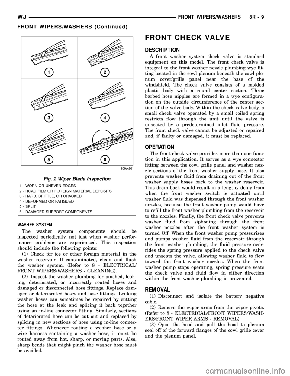
Fig. 2 Wiper Blade Inspection
1 - WORN OR UNEVEN EDGES
2 - ROAD FILM OR FOREIGN MATERIAL DEPOSITS
3 - HARD, BRITTLE, OR CRACKED
4 - DEFORMED OR FATIGUED
5 - SPLIT
6 - DAMAGED SUPPORT COMPONENTS
WJFRONT WIPERS/WASHERS 8R - 9
FRONT WIPERS/WASHERS (Continued)
Page 620 of 2199
(2) Raise and support the vehicle.
(3) Remove the liner from the left front fender
wheel house.
(4) Disconnect the left headlamp and dash wire
harness connector for the front washer pump/motor
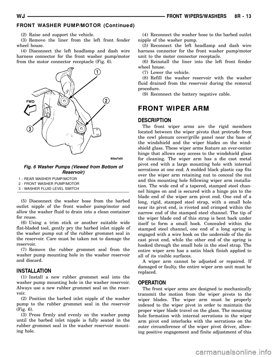
from the motor connector receptacle (Fig. 6).
(5) Disconnect the washer hose from the barbed
outlet nipple of the front washer pump/motor and
allow the washer fluid to drain into a clean container
for reuse.
(6) Using a trim stick or another suitable wide
flat-bladed tool, gently pry the barbed inlet nipple of
the washer pump out of the rubber grommet seal in
the reservoir. Care must be taken not to damage the
reservoir.
(7) Remove the rubber grommet seal from the
washer pump mounting hole in the washer reservoir
and discard.
INSTALLATION
(1) Install a new rubber grommet seal into the
washer pump mounting hole in the washer reservoir.
Always use a new rubber grommet seal on the reser-
voir.
(2) Position the barbed inlet nipple of the washer
pump to the rubber grommet seal in the reservoir
(Fig. 6).
(3) Press firmly and evenly on the washer pump
until the barbed inlet nipple is fully seated in the
rubber grommet seal in the washer reservoir mount-
ing hole.(4) Reconnect the washer hose to the barbed outlet
nipple of the washer pump.
(5) Reconnect the left headlamp and dash wire
harness connector for the front washer pump/motor
unit to the motor connector receptacle.
(6) Reinstall the liner into the left front fender
wheel house.
(7) Lower the vehicle.
(8) Refill the washer reservoir with the washer
fluid drained from the reservoir during the removal
procedure.
(9) Reconnect the battery negative cable.
FRONT WIPER ARM
DESCRIPTION
The front wiper arms are the rigid members
located between the wiper pivots that protrude from
the cowl plenum cover/grille panel near the base of
the windshield and the wiper blades on the wind-
shield glass. These wiper arms feature an over-center
hinge that allows easy access to the windshield glass
for cleaning. The wiper arm has a die cast metal
pivot end with a large mounting hole with internal
serrations at one end. A molded black plastic cap fits
over the wiper arm retaining nut to conceal the nut
and this mounting hole following wiper arm installa-
tion. The wide end of a tapered, stamped steel chan-
nel hinges on and is secured with a hinge pin to the
blade end of the wiper arm pivot end. One end of a
long, rigid, stamped steel strap, with a small hole
near its pivot end, is riveted and crimped within the
narrow end of the stamped steel channel. The tip of
the wiper blade end of this strap is bent back under
itself to form a small hook. Concealed within the
stamped steel channel, one end of a long spring is
engaged with a wire hook on the underside of the die
cast pivot end, while the other end of the spring is
hooked through the small hole in the steel strap. The
entire wiper arm has a satin black finish applied to
all of its visible surfaces.
A wiper arm cannot be adjusted or repaired. If
damaged or faulty, the entire wiper arm unit must be
replaced.
OPERATION
The front wiper arms are designed to mechanically
transmit the motion from the wiper pivots to the
wiper blades. The wiper arm must be properly
indexed to the wiper pivot in order to maintain the
proper wiper blade travel on the glass. The mounting
hole formation with internal serrations in the wiper
arm pivot end interlocks with the serrations on the
outer circumference of the wiper pivot driver, allow-
ing positive engagement and finite adjustment of this
Fig. 6 Washer Pumps (Viewed from Bottom of
Reservoir)
1 - REAR WASHER PUMP/MOTOR
2 - FRONT WASHER PUMP/MOTOR
3 - WASHER FLUID LEVEL SWITCH
WJFRONT WIPERS/WASHERS 8R - 13
FRONT WASHER PUMP/MOTOR (Continued)
Page 626 of 2199
the more frequently the RSM will send wipe com-
mands to the BCM to operate the front wiper system.
The RSM operates on battery current received
through a fuse in the Junction Block (JB) on a fused
B(+) circuit. This circuit is switched by the power
accessory (sunroof) delay relay in the JB so that the
RSM will operate whenever the relay is energized by
the BCM. The RSM receives ground at all times
through a take out of the left body wire harness with
an eyelet terminal that is secured by a ground screw
to the front seat crossmember on the floor panel
under the left front seat. It is important to note that
the default condition for the wiper system is auto-
matic wipers Off; therefore, if no message is received
from the RSM by the BCM for more than about five
seconds, the automatic wipers will be disabled and
the BCM will default the front wiper system opera-
tion to the low speed continuous wipe mode.
The RSM ground and battery current inputs can be
diagnosed using conventional diagnostic tools and
methods. However, conventional diagnostic methods
may not prove conclusive in the diagnosis of the RSM
internal circuitry, the BCM, the PCI data bus net-
work, or the electronic messages received and trans-
mitted by the RSM over the PCI data bus. The most
reliable, efficient, and accurate means to diagnose
the RSM requires the use of a DRBIIItscan tool.
Refer to the appropriate diagnostic information.
REMOVAL
WARNING: ON VEHICLES EQUIPPED WITH AIR-
BAGS, DISABLE THE SUPPLEMENTAL RESTRAINT
SYSTEM BEFORE ATTEMPTING ANY STEERING
WHEEL, STEERING COLUMN, DRIVER AIRBAG,
PASSENGER AIRBAG, SIDE CURTAIN AIRBAG,
FRONT IMPACT SENSOR, SIDE IMPACT SENSOR,
OR INSTRUMENT PANEL COMPONENT DIAGNOSIS
OR SERVICE. DISCONNECT AND ISOLATE THE
BATTERY NEGATIVE (GROUND) CABLE, THEN
WAIT TWO MINUTES FOR THE SYSTEM CAPACI-
TOR TO DISCHARGE BEFORE PERFORMING FUR-
THER DIAGNOSIS OR SERVICE. THIS IS THE ONLY
SURE WAY TO DISABLE THE SUPPLEMENTAL
RESTRAINT SYSTEM. FAILURE TO TAKE THE
PROPER PRECAUTIONS COULD RESULT IN ACCI-
DENTAL AIRBAG DEPLOYMENT AND POSSIBLE
PERSONAL INJURY.
(1) Disconnect and isolate the battery negative
cable.
(2) Adjust the inside rear view mirror on the wind-
shield downward far enough to access the lower edge
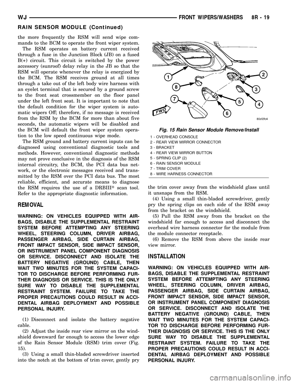
of the Rain Sensor Module (RSM) trim cover (Fig.
15).
(3) Using a small thin-bladed screwdriver inserted
into the notch at the bottom of trim cover, gently prythe trim cover away from the windshield glass until
it unsnaps from the RSM.
(4) Using a small thin-bladed screwdriver, gently
pry the spring clips on each side of the RSM away
from the bracket on the windshield.
(5) Pull the RSM away from the bracket on the
windshield far enough to access and disconnect the
overhead wire harness connector for the module from
the module connector receptacle.
(6) Remove the RSM from above the inside rear
view mirror.
INSTALLATION
WARNING: ON VEHICLES EQUIPPED WITH AIR-
BAGS, DISABLE THE SUPPLEMENTAL RESTRAINT
SYSTEM BEFORE ATTEMPTING ANY STEERING
WHEEL, STEERING COLUMN, DRIVER AIRBAG,
PASSENGER AIRBAG, SIDE CURTAIN AIRBAG,
FRONT IMPACT SENSOR, SIDE IMPACT SENSOR,
OR INSTRUMENT PANEL COMPONENT DIAGNOSIS
OR SERVICE. DISCONNECT AND ISOLATE THE
BATTERY NEGATIVE (GROUND) CABLE, THEN
WAIT TWO MINUTES FOR THE SYSTEM CAPACI-
TOR TO DISCHARGE BEFORE PERFORMING FUR-
THER DIAGNOSIS OR SERVICE. THIS IS THE ONLY
SURE WAY TO DISABLE THE SUPPLEMENTAL
RESTRAINT SYSTEM. FAILURE TO TAKE THE
PROPER PRECAUTIONS COULD RESULT IN ACCI-
DENTAL AIRBAG DEPLOYMENT AND POSSIBLE
PERSONAL INJURY.
Fig. 15 Rain Sensor Module Remove/Install
1 - OVERHEAD CONSOLE
2 - REAR VIEW MIRROR CONNECTOR
3 - BRACKET
4 - REAR VIEW MIRROR BUTTON
5 - SPRING CLIP (2)
6 - RAIN SENSOR MODULE
7 - TRIM COVER
8 - WIRE HARNESS CONNECTOR
WJFRONT WIPERS/WASHERS 8R - 19
RAIN SENSOR MODULE (Continued)
Page 633 of 2199

REMOVAL
The washer fluid level switch can be removed from
the washer reservoir without removing the reservoir
from the vehicle.
(1) Disconnect and isolate the battery negative
cable.
(2) Remove the one screw that secures the washer
reservoir filler neck to the left inner fender shield.
(3) Raise and support the vehicle.
(4) Remove the liner from the left front fender
wheel house.
(5) Disconnect the washer hose from the barbed
outlet nipple of the rearmost (front) washer pump/
motor unit and allow the washer fluid to drain into a
clean container for reuse.
(6) Remove the two screws that secure the inboard
mounting flange of the washer reservoir to the left
inner wheel house.
(7) Pull the bottom of the washer reservoir rear-
ward far enough to access the left headlamp and
dash wire harness connector for the washer fluid
level switch on the front of the reservoir.
(8) Disconnect the left headlamp and dash wire
harness connector for the washer fluid level switch
from the switch connector receptacle.
(9) Using a trim stick or another suitable wide
flat-bladed tool, gently pry the barbed nipple of the
washer fluid level switch out of the rubber grommet
seal on the front of the reservoir (Fig. 21). Care must
be taken not to damage the reservoir.
(10) Remove the washer fluid level switch and
float from the washer reservoir.
(11) Remove the rubber grommet seal from the
washer fluid level switch mounting hole in the
washer reservoir and discard.
INSTALLATION
(1) Install a new rubber grommet seal into the
washer fluid level switch mounting hole in the front
of the washer reservoir. Always use a new rubber
grommet seal on the reservoir.
(2) Position the float of the washer fluid level
switch through the rubber grommet seal in the
washer reservoir (Fig. 21). The connector receptacle
of the washer fluid level switch should be pointed
downward.
(3) Press firmly and evenly on the washer fluid
level switch using hand pressure until the barbed
nipple is fully seated in the rubber grommet seal in
the washer reservoir mounting hole.(4) Reconnect the left headlamp and dash wire
harness connector for the washer fluid level switch to
the switch connector receptacle.
(5) Reconnect the washer hose to the barbed outlet
nipple of the front washer pump/motor unit.
(6) Install and tighten the two screws that secure
the inboard mounting flange of the washer reservoir
to the left inner wheel house. Tighten the screws to
7.4 N´m (66 in. lbs.).
(7) Reinstall the liner into the left front fender
wheel house.
(8) Lower the vehicle.
(9) Install and tighten the one screw that secures
the washer reservoir filler neck to the left inner
fender shield. Tighten the screw to 7.4 N´m (66 in.
lbs.).
(10) Fill the washer reservoir with the washer
fluid drained from the reservoir during the removal
procedure.
(11) Reconnect the battery negative cable.
Fig. 21 Washer Fluid Level Switch Remove/Install
1 - WASHER RESERVOIR
2 - WASHER FLUID LEVEL SWITCH
3 - GROMMET SEAL
8R - 26 FRONT WIPERS/WASHERSWJ
WASHER FLUID LEVEL SWITCH (Continued)
Page 638 of 2199
(2) Position the wiper high/low relay in the proper
receptacle in the PDC.
(3) Align the wiper high/low relay terminals with
the terminal cavities in the PDC receptacle.
(4) Push firmly and evenly on the top of the wiper
high/low relay until the terminals are fully seated in
the terminal cavities in the PDC receptacle.
(5) Reinstall the cover onto the PDC.
(6) Reconnect the battery negative cable.
WIPER ON/OFF RELAY
DESCRIPTION
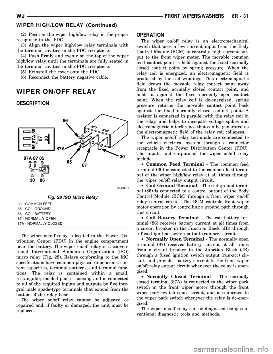
The wiper on/off relay is located in the Power Dis-
tribution Center (PDC) in the engine compartment
near the battery. The wiper on/off relay is a conven-
tional International Standards Organization (ISO)
micro relay (Fig. 28). Relays conforming to the ISO
specifications have common physical dimensions, cur-
rent capacities, terminal patterns, and terminal func-
tions. The relay is contained within a small,
rectangular, molded plastic housing and is connected
to all of the required inputs and outputs by five inte-
gral male spade-type terminals that extend from the
bottom of the relay base.
The wiper on/off relay cannot be adjusted or
repaired and, if faulty or damaged, the unit must be
replaced.
OPERATION
The wiper on/off relay is an electromechanical
switch that uses a low current input from the Body
Control Module (BCM) to control a high current out-
put to the front wiper motor. The movable common
feed contact point is held against the fixed normally
closed contact point by spring pressure. When the
relay coil is energized, an electromagnetic field is
produced by the coil windings. This electromagnetic
field draws the movable relay contact point away
from the fixed normally closed contact point, and
holds it against the fixed normally open contact
point. When the relay coil is de-energized, spring
pressure returns the movable contact point back
against the fixed normally closed contact point. A
resistor is connected in parallel with the relay coil in
the relay, and helps to dissipate voltage spikes and
electromagnetic interference that can be generated as
the electromagnetic field of the relay coil collapses.
The wiper on/off relay terminals are connected to
the vehicle electrical system through a connector
receptacle in the Power Distribution Center (PDC).
The inputs and outputs of the wiper on/off relay
include:
²Common Feed Terminal- The common feed
terminal (30) is connected to the common feed termi-
nal of the wiper high/low relay at all times through
the wiper on/off relay output circuit.
²Coil Ground Terminal- The coil ground termi-
nal (85) is connected to a control output of the Body
Control Module (BCM) through a front wiper on/off
relay control circuit. The BCM controls front wiper
motor operation by controlling a ground path through
this circuit.
²Coil Battery Terminal- The coil battery ter-
minal (86) receives battery current at all times from
a circuit breaker in the Junction Block (JB) through
a fused ignition switch output (run-acc) circuit.
²Normally Open Terminal- The normally open
terminal (87) receives battery current at all times
from a circuit breaker in the Junction Block (JB)
through a fused ignition switch output (run-acc) cir-
cuit, and provides battery current to the front wiper
on/off relay output circuit whenever the relay is ener-
gized.
²Normally Closed Terminal- The normally
closed terminal (87A) is connected to the wiper park
switch in the front wiper motor through the front
wiper park switch sense circuit, and is connected to
the wiper park switch whenever the relay is de-ener-
gized.
The wiper on/off relay can be diagnosed using con-
ventional diagnostic tools and methods.
Fig. 28 ISO Micro Relay
30 - COMMON FEED
85 - COIL GROUND
86 - COIL BATTERY
87 - NORMALLY OPEN
87A - NORMALLY CLOSED
WJFRONT WIPERS/WASHERS 8R - 31
WIPER HIGH/LOW RELAY (Continued)
Page 639 of 2199
DIAGNOSIS AND TESTING - WIPER ON/OFF
RELAY
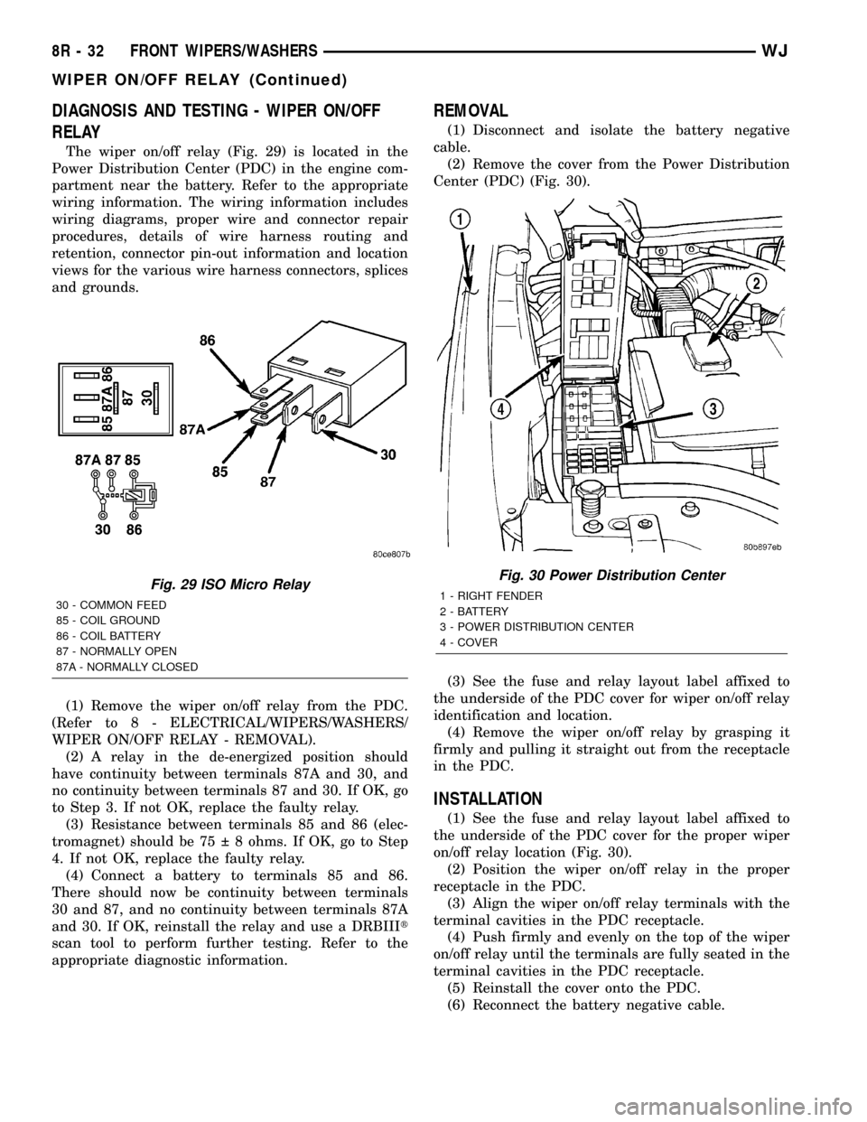
The wiper on/off relay (Fig. 29) is located in the
Power Distribution Center (PDC) in the engine com-
partment near the battery. Refer to the appropriate
wiring information. The wiring information includes
wiring diagrams, proper wire and connector repair
procedures, details of wire harness routing and
retention, connector pin-out information and location
views for the various wire harness connectors, splices
and grounds.
(1) Remove the wiper on/off relay from the PDC.
(Refer to 8 - ELECTRICAL/WIPERS/WASHERS/
WIPER ON/OFF RELAY - REMOVAL).
(2) A relay in the de-energized position should
have continuity between terminals 87A and 30, and
no continuity between terminals 87 and 30. If OK, go
to Step 3. If not OK, replace the faulty relay.
(3) Resistance between terminals 85 and 86 (elec-
tromagnet) should be 75 8 ohms. If OK, go to Step
4. If not OK, replace the faulty relay.
(4) Connect a battery to terminals 85 and 86.
There should now be continuity between terminals
30 and 87, and no continuity between terminals 87A
and 30. If OK, reinstall the relay and use a DRBIIIt
scan tool to perform further testing. Refer to the
appropriate diagnostic information.
REMOVAL
(1) Disconnect and isolate the battery negative
cable.
(2) Remove the cover from the Power Distribution
Center (PDC) (Fig. 30).
(3) See the fuse and relay layout label affixed to
the underside of the PDC cover for wiper on/off relay
identification and location.
(4) Remove the wiper on/off relay by grasping it
firmly and pulling it straight out from the receptacle
in the PDC.
INSTALLATION
(1) See the fuse and relay layout label affixed to
the underside of the PDC cover for the proper wiper
on/off relay location (Fig. 30).
(2) Position the wiper on/off relay in the proper
receptacle in the PDC.
(3) Align the wiper on/off relay terminals with the
terminal cavities in the PDC receptacle.
(4) Push firmly and evenly on the top of the wiper
on/off relay until the terminals are fully seated in the
terminal cavities in the PDC receptacle.
(5) Reinstall the cover onto the PDC.
(6) Reconnect the battery negative cable.
Fig. 29 ISO Micro Relay
30 - COMMON FEED
85 - COIL GROUND
86 - COIL BATTERY
87 - NORMALLY OPEN
87A - NORMALLY CLOSED
Fig. 30 Power Distribution Center
1 - RIGHT FENDER
2 - BATTERY
3 - POWER DISTRIBUTION CENTER
4 - COVER
8R - 32 FRONT WIPERS/WASHERSWJ
WIPER ON/OFF RELAY (Continued)
Page 646 of 2199
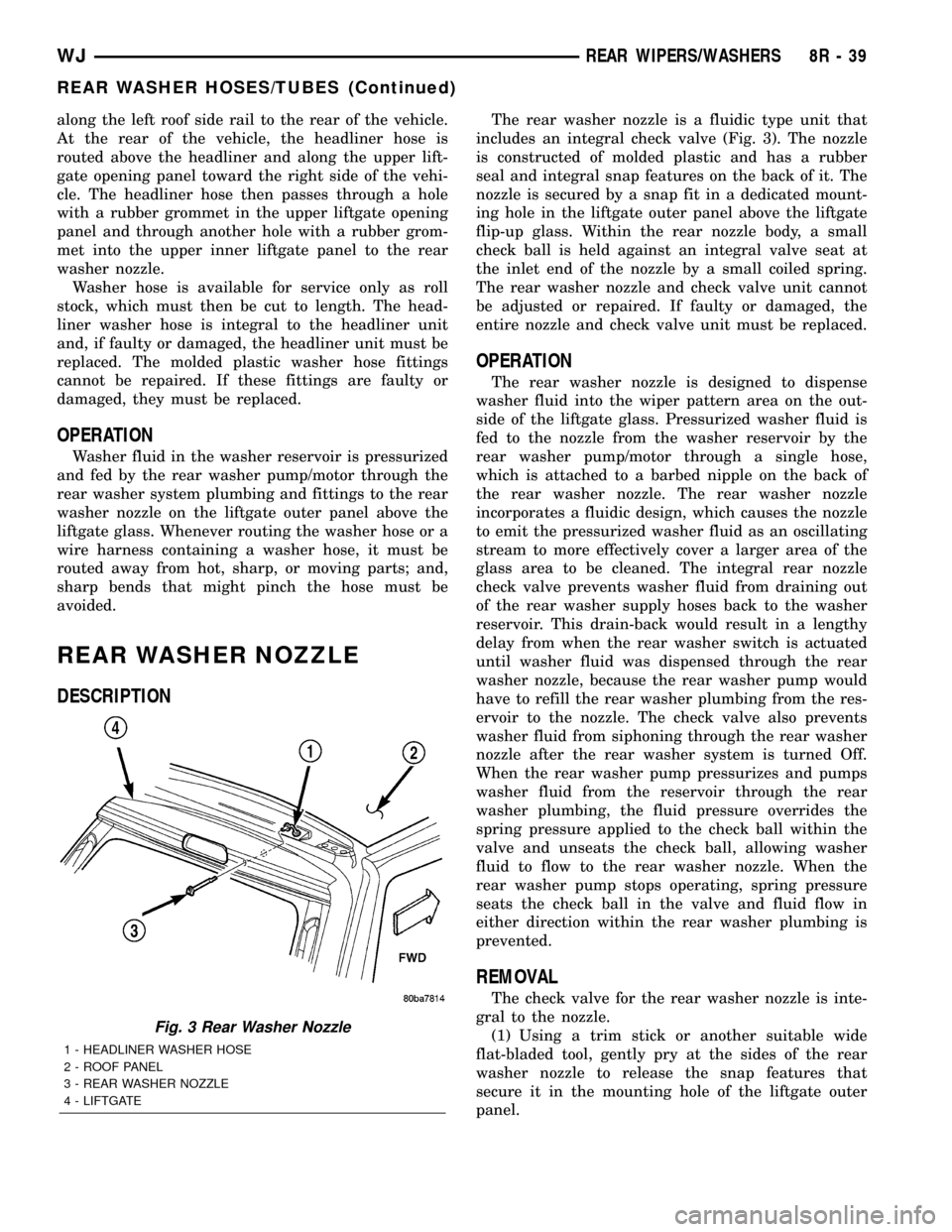
along the left roof side rail to the rear of the vehicle.
At the rear of the vehicle, the headliner hose is
routed above the headliner and along the upper lift-
gate opening panel toward the right side of the vehi-
cle. The headliner hose then passes through a hole
with a rubber grommet in the upper liftgate opening
panel and through another hole with a rubber grom-
met into the upper inner liftgate panel to the rear
washer nozzle.
Washer hose is available for service only as roll
stock, which must then be cut to length. The head-
liner washer hose is integral to the headliner unit
and, if faulty or damaged, the headliner unit must be
replaced. The molded plastic washer hose fittings
cannot be repaired. If these fittings are faulty or
damaged, they must be replaced.
OPERATION
Washer fluid in the washer reservoir is pressurized
and fed by the rear washer pump/motor through the
rear washer system plumbing and fittings to the rear
washer nozzle on the liftgate outer panel above the
liftgate glass. Whenever routing the washer hose or a
wire harness containing a washer hose, it must be
routed away from hot, sharp, or moving parts; and,
sharp bends that might pinch the hose must be
avoided.
REAR WASHER NOZZLE
DESCRIPTION
The rear washer nozzle is a fluidic type unit that
includes an integral check valve (Fig. 3). The nozzle
is constructed of molded plastic and has a rubber
seal and integral snap features on the back of it. The
nozzle is secured by a snap fit in a dedicated mount-
ing hole in the liftgate outer panel above the liftgate
flip-up glass. Within the rear nozzle body, a small
check ball is held against an integral valve seat at
the inlet end of the nozzle by a small coiled spring.
The rear washer nozzle and check valve unit cannot
be adjusted or repaired. If faulty or damaged, the
entire nozzle and check valve unit must be replaced.
OPERATION
The rear washer nozzle is designed to dispense
washer fluid into the wiper pattern area on the out-
side of the liftgate glass. Pressurized washer fluid is
fed to the nozzle from the washer reservoir by the
rear washer pump/motor through a single hose,
which is attached to a barbed nipple on the back of
the rear washer nozzle. The rear washer nozzle
incorporates a fluidic design, which causes the nozzle
to emit the pressurized washer fluid as an oscillating
stream to more effectively cover a larger area of the
glass area to be cleaned. The integral rear nozzle
check valve prevents washer fluid from draining out
of the rear washer supply hoses back to the washer
reservoir. This drain-back would result in a lengthy
delay from when the rear washer switch is actuated
until washer fluid was dispensed through the rear
washer nozzle, because the rear washer pump would
have to refill the rear washer plumbing from the res-
ervoir to the nozzle. The check valve also prevents
washer fluid from siphoning through the rear washer
nozzle after the rear washer system is turned Off.
When the rear washer pump pressurizes and pumps
washer fluid from the reservoir through the rear
washer plumbing, the fluid pressure overrides the
spring pressure applied to the check ball within the
valve and unseats the check ball, allowing washer
fluid to flow to the rear washer nozzle. When the
rear washer pump stops operating, spring pressure
seats the check ball in the valve and fluid flow in
either direction within the rear washer plumbing is
prevented.
REMOVAL
The check valve for the rear washer nozzle is inte-
gral to the nozzle.
(1) Using a trim stick or another suitable wide
flat-bladed tool, gently pry at the sides of the rear
washer nozzle to release the snap features that
secure it in the mounting hole of the liftgate outer
panel.
Fig. 3 Rear Washer Nozzle
1 - HEADLINER WASHER HOSE
2 - ROOF PANEL
3 - REAR WASHER NOZZLE
4 - LIFTGATE
WJREAR WIPERS/WASHERS 8R - 39
REAR WASHER HOSES/TUBES (Continued)
Page 648 of 2199
the washer fluid and forces it through the pump out-
let nipple, the rear washer plumbing, and the rear
washer nozzle onto the liftgate glass.
REMOVAL
(1) Disconnect and isolate the battery negative
cable.
(2) Raise and support the vehicle.
(3) Remove the liner from the left front fender
wheel house.
(4) Disconnect the left headlamp and dash wire
harness connector for the rear washer pump/motor
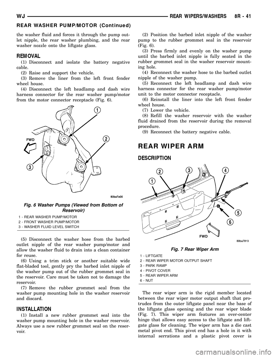
from the motor connector receptacle (Fig. 6).
(5) Disconnect the washer hose from the barbed
outlet nipple of the rear washer pump/motor and
allow the washer fluid to drain into a clean container
for reuse.
(6) Using a trim stick or another suitable wide
flat-bladed tool, gently pry the barbed inlet nipple of
the washer pump out of the rubber grommet seal in
the reservoir. Care must be taken not to damage the
reservoir.
(7) Remove the rubber grommet seal from the
washer pump mounting hole in the washer reservoir
and discard.
INSTALLATION
(1) Install a new rubber grommet seal into the
washer pump mounting hole in the washer reservoir.
Always use a new rubber grommet seal on the reser-
voir.(2) Position the barbed inlet nipple of the washer
pump to the rubber grommet seal in the reservoir
(Fig. 6).
(3) Press firmly and evenly on the washer pump
until the barbed inlet nipple is fully seated in the
rubber grommet seal in the washer reservoir mount-
ing hole.
(4) Reconnect the washer hose to the barbed outlet
nipple of the washer pump.
(5) Reconnect the left headlamp and dash wire
harness connector for the rear washer pump/motor
unit to the motor connector receptacle.
(6) Reinstall the liner into the left front fender
wheel house.
(7) Lower the vehicle.
(8) Refill the washer reservoir with the washer
fluid drained from the reservoir during the removal
procedure.
(9) Reconnect the battery negative cable.
REAR WIPER ARM
DESCRIPTION
The rear wiper arm is the rigid member located
between the rear wiper motor output shaft that pro-
trudes from the outer liftgate panel near the base of
the liftgate glass opening and the rear wiper blade
(Fig. 7). This wiper arm features an over-center
hinge that allows easy access to the liftgate and lift-
gate glass for cleaning. The wiper arm has a die cast
metal pivot end. This pivot end has a hole in it with
internal serrations and a plastic pivot cover is
Fig. 6 Washer Pumps (Viewed from Bottom of
Reservoir)
1 - REAR WASHER PUMP/MOTOR
2 - FRONT WASHER PUMP/MOTOR
3 - WASHER FLUID LEVEL SWITCH
Fig. 7 Rear Wiper Arm
1 - LIFTGATE
2 - REAR WIPER MOTOR OUTPUT SHAFT
3 - PARK RAMP
4 - PIVOT COVER
5 - REAR WIPER ARM
6 - NUT
WJREAR WIPERS/WASHERS 8R - 41
REAR WASHER PUMP/MOTOR (Continued)