WIRING JEEP GRAND CHEROKEE 2002 WJ / 2.G Workshop Manual
[x] Cancel search | Manufacturer: JEEP, Model Year: 2002, Model line: GRAND CHEROKEE, Model: JEEP GRAND CHEROKEE 2002 WJ / 2.GPages: 2199, PDF Size: 76.01 MB
Page 1531 of 2199
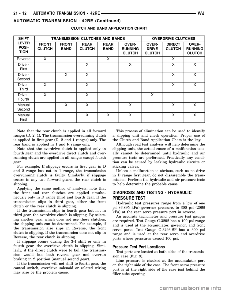
CLUTCH AND BAND APPLICATION CHART
SHIFT
LEVER
POSI-
TIONTRANSMISSION CLUTCHES AND BANDS OVERDRIVE CLUTCHES
FRONT
CLUTCHFRONT
BANDREAR
CLUTCHREAR
BANDOVER-
RUNNING
CLUTCHOVER-
DRIVE
CLUTCHDIRECT
CLUTCHOVER-
RUNNING
CLUTCH
Reverse X X X
Drive -
FirstXXXX
Drive -
SecondXX X X
Drive -
ThirdXX XX
Drive -
FourthXX X
Manual
SecondXXXXX
Manual
FirstXX X X X
Note that the rear clutch is applied in all forward
ranges (D, 2, 1). The transmission overrunning clutch
is applied in first gear (D, 2 and 1 ranges) only. The
rear band is applied in 1 and R range only.
Note that the overdrive clutch is applied only in
fourth gear and the overdrive direct clutch and over-
running clutch are applied in all ranges except fourth
gear.
For example: If slippage occurs in first gear in D
and 2 range but not in 1 range, the transmission
overrunning clutch is faulty. Similarly, if slippage
occurs in any two forward gears, the rear clutch is
slipping.
Applying the same method of analysis, note that
the front and rear clutches are applied simulta-
neously only in D range third and fourth gear. If the
transmission slips in third gear, either the front
clutch or the rear clutch is slipping.
If the transmission slips in fourth gear but not in
third gear, the overdrive clutch is slipping. By select-
ing another gear which does not use these clutches,
the slipping unit can be determined. For example, if
the transmission also slips in Reverse, the front
clutch is slipping. If the transmission does not slip in
Reverse, the rear clutch is slipping.
If slippage occurs during the 3-4 shift or only in
fourth gear, the overdrive clutch is slipping. Simi-
larly, if the direct clutch were to fail, the transmis-
sion would lose both reverse gear and overrun
braking in 2 position (manual second gear).
If the transmission will not shift to fourth gear, the
control switch, overdrive solenoid or related wiring
may also be the problem cause.This process of elimination can be used to identify
a slipping unit and check operation. Proper use of
the Clutch and Band Application Chart is the key.
Although road test analysis will help determine the
slipping unit, the actual cause of a malfunction usu-
ally cannot be determined until hydraulic and air
pressure tests are performed. Practically any condi-
tion can be caused by leaking hydraulic circuits or
sticking valves.
Unless a malfunction is obvious, such as no drive
in D range first gear, do not disassemble the trans-
mission. Perform the hydraulic and air pressure tests
to help determine the probable cause.
DIAGNOSIS AND TESTING - HYDRAULIC
PRESSURE TEST
Hydraulic test pressures range from a low of one
psi (6.895 kPa) governor pressure, to 300 psi (2068
kPa) at the rear servo pressure port in reverse.
An accurate tachometer and pressure test gauges
are required. Test Gauge C-3292 has a 100 psi range
and is used at the accumulator, governor, and front
servo ports. Test Gauge C-3293-SP has a 300 psi
range and is used at the rear servo and overdrive
ports where pressures exceed 100 psi.
Pressure Test Port Locations
Test ports are located at both sides of the transmis-
sion case (Fig. 9).
Line pressure is checked at the accumulator port
on the right side of the case. The front servo pressure
port is at the right side of the case just behind the
filler tube opening.
21 - 12 AUTOMATIC TRANSMISSION - 42REWJ
AUTOMATIC TRANSMISSION - 42RE (Continued)
Page 1541 of 2199
CONDITION POSSIBLE CAUSES CORRECTION
GROWLING,
GRATING OR
SCRAPING NOISES1. Drive Plate Broken. 1. Replace.
2. Torque Converter Bolts Hitting
Dust Shield.2. Dust shield bent. Replace or repair.
3. Planetary Gear Set Broken/
Seized.3. Check for debris in oil pan and repair as
required.
4. Overrunning Clutch Worn/
Broken.4. Inspect and check for debris in oil pan. Repair
as required.
5. Oil Pump Components
Scored/Binding.5. Remove, inspect and repair as required.
6. Output Shaft Bearing or Bushing
Damaged.6. Remove, inspect and repair as required.
7. Clutch Operation Faulty. 7. Perform air pressure check and repair as
required.
8. Front and Rear Bands
Mis-adjusted.8. Adjust bands.
DRAGS OR LOCKS
UP1. Fluid Level Low. 1. Check and adjust level.
2. Clutch Dragging/Failed 2. Air pressure check clutch operation and repair
as required.
3. Front or Rear Band Mis-
adjusted.3. Adjust bands.
4. Case Leaks Internally. 4. Check for leakage between passages in case.
5. Servo Band or Linkage
Malfunction.5. Air pressure check servo operation and repair
as required.
6. Overrunning Clutch Worn. 6. Remove and inspect clutch. Repair as required.
7. Planetary Gears Broken. 7. Remove, inspect and repair as required (look
for debris in oil pan).
8. Converter Clutch Dragging. 8. Check for plugged cooler. Perform flow check.
Inspect pump for excessive side clearance.
Replace pump as required.
NO 4-3 DOWNSHIFT 1. Circuit Wiring and/or Connectors
Shorted.1.
Test wiring and connectors with test lamp and
volt/ohmmeter. Repair wiring as necessary. Replace
connectors and/or harnesses as required.
2. PCM Malfunction. 2. Check PCM operation with DRBTscan tool.
Replace PCM only if faulty.
3. TPS Malfunction 3. Check TPS with DRBTscan tool at PCM.
4. Lockup Solenoid Not Venting. 4. Remove valve body and replace solenoid
assembly if plugged or shorted.
5. Overdrive Solenoid Not Venting. 5. Remove valve body and replace solenoid if
plugged or shorted.
6. Valve Body Valve Sticking. 6. Repair stuck 3-4 shift valve or lockup timing
valve.
NO 4-3 DOWNSHIFT
WHEN CONTROL
SWITCH IS TURNED
OFF1. Control Switch Open/Shorted. 1. Test and replace switch if faulty.
2. Overdrive Solenoid Connector
Shorted.2. Test solenoids and replace if seized or shorted.
3. PCM Malfunction. 3.
Test with DRBTscan tool. Replace PCM if faulty.
4. Valve Body Stuck Valves. 4.Repair stuck 3-4, lockup or lockup timing valve.
21 - 22 AUTOMATIC TRANSMISSION - 42REWJ
AUTOMATIC TRANSMISSION - 42RE (Continued)
Page 1542 of 2199
CONDITION POSSIBLE CAUSES CORRECTION
CLUNK NOISE FROM
DRIVELINE ON
CLOSED THROTTLE
4-3 DOWNSHIFT1. Transmission Fluid Low. 1. Add Fluid.
2. Throttle Cable Mis-adjusted. 2. Adjust cable.
3. Overdrive Clutch Select Spacer
Wrong Spacer.3. Replace overdrive piston thrust plate spacer.
3-4 UPSHIFT
OCCURS
IMMEDIATELY AFTER
2-3 SHIFT1. Overdrive Solenoid Connector or
Wiring Shorted.1.
Test connector and wiring for loose connections,
shorts or ground and repair as needed.
2. TPS Malfunction. 2. Test TPS and replace as necessary. Check with
DRBTscan tool.
3. PCM Malfunction. 3. Test PCM with DRBTscan tool and replace
controller if faulty.
4. Overdrive Solenoid Malfunction. 4. Replace solenoid.
5. Valve Body Malfunction. 5. Remove, disassemble, clean and inspect valve
body components. Make sure all valves and plugs
slide freely in bores. Polish valves with crocus
cloth if needed.
WHINE/NOISE
RELATED TO ENGINE
SPEED1. Fluid Level Low. 1. Add fluid and check for leaks.
2. Shift Cable Incorrect Routing. 2. Check shift cable for correct routing. Should not
touch engine or bell housing.
NO 3-4 UPSHIFT 1. O/D Switch In OFF Position. 1. Turn control switch to ON position.
2. Overdrive Circuit Fuse Blown. 2. Replace fuse. Determine why fuse failed and
repair as necessary (i.e., shorts or grounds in
circuit).
3. O/D Switch Wire Shorted/Open
Cut.3. Check wires/connections with 12V test lamp
and voltmeter. Repair damaged or loose
wire/connection as necessary.
4. Distance or Coolant Sensor
Malfunction.4. Check with DRBTscan tool and repair or
replace as necessary.
5. TPS Malfunction. 5. Check with DRBTscan tool and replace if
necessary.
6. Neutral Sense to PCM Wire
Shorted/Cut.6. Test switch/sensor as described in service
section and replace if necessary. Engine no start.
7. PCM Malfunction. 7. Check with DRBTscan tool and replace if
necessary.
8. Overdrive Solenoid Shorted/
Open.8. Replace solenoid if shorted or open and repair
loose or damaged wires (DRBTscan tool).
9. Solenoid Feed Orifice in Valve
Body Blocked.9. Remove, disassemble, and clean valve body
thoroughly. Check feed orifice.
10. Overdrive Clutch Failed. 10. Disassemble overdrive and repair as needed.
11. Hydraulic Pressure Low. 11. Pressure test transmission to determine
cause.
12. Valve Body Valve Stuck. 12. Repair stuck 3-4 shift valve, 3-4 timing valve.
13. O/D Piston Incorrect Spacer. 13. Remove unit, check end play and install
correct spacer.
14. Overdrive Piston Seal Failure. 14. Replace both seals.
15. O/D Check Valve/Orifice Failed. 15. Check for free movement and secure
assembly (in piston retainer). Check ball bleed
orifice.
WJAUTOMATIC TRANSMISSION - 42RE 21 - 23
AUTOMATIC TRANSMISSION - 42RE (Continued)
Page 1543 of 2199
CONDITION POSSIBLE CAUSES CORRECTION
SLIPS IN OVERDRIVE
FOURTH GEAR1. Fluid Level Low. 1. Add fluid and check for leaks.
2. Overdrive Clutch Pack Worn. 2. Remove overdrive unit and rebuild clutch pack.
3. Overdrive Piston Retainer Bleed
Orifice Blown Out.3. Disassemble transmission, remove retainer and
replace orifice.
4. Overdrive Piston or Seal
Malfunction.4. Remove overdrive unit. Replace seals if worn.
Replace piston if damaged. If piston retainer is
damaged, remove and disassemble the
transmission.
5. 3-4 Shift Valve, Timing Valve or
Accumulator Malfunction.5. Remove and overhaul valve body. Replace
accumulator seals. Make sure all valves operate
freely in bores and do not bind or stick. Make sure
valve body screws are correctly tightened and
separator plates are properly positioned.
6. Overdrive Unit Thrust Bearing
Failure.6. Disassemble overdrive unit and replace thrust
bearing (NO. 1 thrust bearing is between
overdrive piston and clutch hub; NO. 2 thrust
bearing is between the planetary gear and the
direct clutch spring plate; NO. 3 thrust bearing is
between overrunning clutch hub and output shaft).
7. O/D Check Valve/Bleed Orifice
Failure.7. Check for function/secure orifice insert in O/D
piston retainer.
DELAYED 3-4
UPSHIFT (SLOW TO
ENGAGE)1. Fluid Level Low. 1. Add fluid and check for leaks.
2. Throttle Valve Cable Mis-
adjusted.2. Adjust throttle valve cable.
3. Overdrive Clutch Pack
Worn/Burnt.3. Remove unit and rebuild clutch pack.
4. TPS Faulty. 4. Test with DRBTscan tool and replace as
necessary
5. Overdrive Clutch Bleed Orifice
Plugged.5. Disassemble transmission and replace orifice.
6. Overdrive Solenoid or Wiring
Shorted/Open.6. Test solenoid and check wiring for loose/
corroded connections or shorts/grounds. Replace
solenoid if faulty and repair wiring if necessary.
7. Overdrive Excess Clearance. 7. Remove unit. Measure end play and select
proper spacer.
8. O/D Check Valve Missing or
Stuck.8. Check for presence of check valve. Repair or
replace as required.
TORQUE
CONVERTER LOCKS
UP IN SECOND
AND/OR THIRD
GEARLockup Solenoid, Relay or Wiring
Shorted/Open.Test solenoid, relay and wiring for continuity,
shorts or grounds. Replace solenoid and relay if
faulty. Repair wiring and connectors as necessary.
HARSH 1-2, 2-3, 3-4
OR 3-2 SHIFTSLockup Solenoid Malfunction. Remove valve body and replace solenoid
assembly.
21 - 24 AUTOMATIC TRANSMISSION - 42REWJ
AUTOMATIC TRANSMISSION - 42RE (Continued)
Page 1560 of 2199

(32) Install valve body as follows:
(a) Align and carefully insert park rod into pawl.
Rod will make click noise as it enters pawl. Move
rod slightly to check engagement.
(b) Align and seat valve body on case. Be sure
manual lever shaft and overdrive connector are
fully seated in case. Also be sure valve body wiring
is not pinched or kinked.
(c) Install and start all valve body attaching
bolts by hand. Then tighten bolts evenly, in a diag-
onal pattern to 12 N´m (105 in. lbs.) torque. Do not
overtighten valve body bolts. This could result in
distortion and cross leakage after installation.
CAUTION: It is possible for the park rod to displace
into a cavity just above the pawl sprag during
installation. Make sure the rod is actually engaged
in the pawl and has not displaced into the cavity.
(33) Install new filter on valve body. Tighten filter
screws to 4 N´m (35 in. lbs.).
(34) Adjust front and rear bands.
(35) Install seal on park/neutral position switch.
Then install and tighten switch to 34 N´m (25 ft.
lbs.).
(36) Install magnet in oil pan. Magnet goes on
small protrusion at corner of pan.
(37) Position new oil pan gasket on case and
install oil pan. Tighten pan bolts to 17 N´m (13 ft.
lbs.).
(38) Install new valve body manual shaft seal in
case (Fig. 60). Lubricate seal lip and manual shaft
with petroleum jelly. Start seal over shaft and into
case. Seat seal with 15/16 inch, deep well socket.
(39) Install throttle valve and shift selector levers
on valve body manual lever shaft.INSTALLATION
(1) Check torque converter hub and hub drive
notches for sharp edges burrs, scratches, or nicks.
Polish the hub and notches with 320/400 grit paper
and crocus cloth if necessary. The hub must be
smooth to avoid damaging pump seal during installa-
tion.
(2) Lubricate oil pump seal lip with transmission
fluid.
(3) Align converter and oil pump.
(4) Carefully insert converter in oil pump. Then
rotate converter back and forth until fully seated in
pump gears.
(5) Check converter seating with steel scale and
straightedge (Fig. 61). Surface of converter lugs
should be 1/2 in. to rear of straightedge when con-
verter is fully seated.
(6) Temporarily secure converter with C-clamp.
(7) Position transmission on jack and secure it
with chains.
(8) Check condition of converter driveplate.
Replace the plate if cracked, distorted or damaged.
Also be sure transmission dowel pins are seated in
engine block and protrude far enough to hold trans-
mission in alignment.
(9) Apply a light coating of MopartHigh Temp
grease to the torque converter hub pocket in the rear
of the crankshaft
(10) Raise transmission and align converter with
drive plate and converter housing with engine block.
Fig. 60 Installing Manual Lever Shaft Seal
1 - 15/1688SOCKET
2 - SEAL
Fig. 61 Checking Torque Converter Seating - Typical
1 - SCALE
2 - STRAIGHTEDGE
WJAUTOMATIC TRANSMISSION - 42RE 21 - 41
AUTOMATIC TRANSMISSION - 42RE (Continued)
Page 1575 of 2199
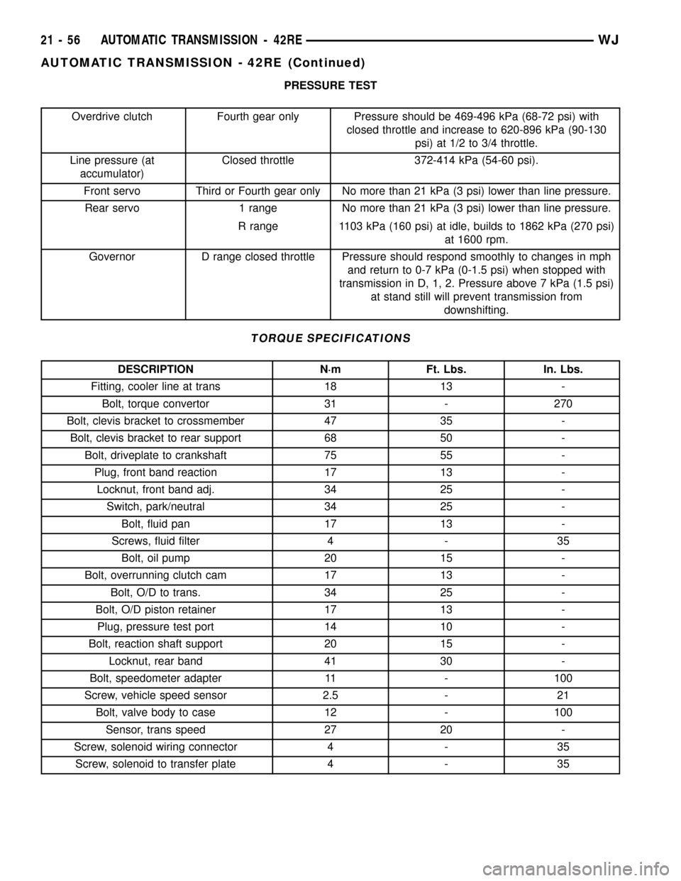
PRESSURE TEST
Overdrive clutch Fourth gear only Pressure should be 469-496 kPa (68-72 psi) with
closed throttle and increase to 620-896 kPa (90-130
psi) at 1/2 to 3/4 throttle.
Line pressure (at
accumulator)Closed throttle 372-414 kPa (54-60 psi).
Front servo Third or Fourth gear only No more than 21 kPa (3 psi) lower than line pressure.
Rear servo 1 range No more than 21 kPa (3 psi) lower than line pressure.
R range 1103 kPa (160 psi) at idle, builds to 1862 kPa (270 psi)
at 1600 rpm.
Governor D range closed throttle Pressure should respond smoothly to changes in mph
and return to 0-7 kPa (0-1.5 psi) when stopped with
transmission in D, 1, 2. Pressure above 7 kPa (1.5 psi)
at stand still will prevent transmission from
downshifting.
TORQUE SPECIFICATIONS
DESCRIPTION N´m Ft. Lbs. In. Lbs.
Fitting, cooler line at trans 18 13 -
Bolt, torque convertor 31 - 270
Bolt, clevis bracket to crossmember 47 35 -
Bolt, clevis bracket to rear support 68 50 -
Bolt, driveplate to crankshaft 75 55 -
Plug, front band reaction 17 13 -
Locknut, front band adj. 34 25 -
Switch, park/neutral 34 25 -
Bolt, fluid pan 17 13 -
Screws, fluid filter 4 - 35
Bolt, oil pump 20 15 -
Bolt, overrunning clutch cam 17 13 -
Bolt, O/D to trans. 34 25 -
Bolt, O/D piston retainer 17 13 -
Plug, pressure test port 14 10 -
Bolt, reaction shaft support 20 15 -
Locknut, rear band 41 30 -
Bolt, speedometer adapter 11 - 100
Screw, vehicle speed sensor 2.5 - 21
Bolt, valve body to case 12 - 100
Sensor, trans speed 27 20 -
Screw, solenoid wiring connector 4 - 35
Screw, solenoid to transfer plate 4 - 35
21 - 56 AUTOMATIC TRANSMISSION - 42REWJ
AUTOMATIC TRANSMISSION - 42RE (Continued)
Page 1606 of 2199

DIAGNOSIS AND TESTING - OVERDRIVE
ELECTRICAL CONTROLS
The overdrive off switch, valve body solenoid, case
connectors and related wiring can all be tested with
a 12 volt test lamp or a volt/ohmmeter. Check conti-
nuity of each component when diagnosis indicates
this is necessary.
Switch and solenoid continuity should be checked
whenever the transmission fails to shift into fourth
gear range.
OVERDRIVE UNIT
REMOVAL
(1) Shift transmission into PARK.
(2) Raise vehicle.
(3) Remove transfer case, if equipped.
(4) Mark propeller shaft universal joint(s) and axle
pinion yoke, or the companion flange and flange
yoke, for alignment reference at installation, if necc-
esary.
(5) Disconnect and remove the rear propeller shaft,
if necessary. (Refer to 3 - DIFFERENTIAL & DRIV-
ELINE/PROPELLER SHAFT/PROPELLER SHAFT -
REMOVAL)
(6) Remove transmission oil pan, remove gasket,
drain oil and reinstall pan.
(7) If overdrive unit had malfunctioned, or if fluid
is contaminated, remove entire transmission. If diag-
nosis indicated overdrive problems only, remove just
the overdrive unit.
(8) Support transmission with transmission jack.
(9) Remove bolts attaching overdrive unit to trans-
mission (Fig. 126).
CAUTION: Support the overdrive unit with a jack
before moving it rearward. This is necessary to pre-
vent damaging the intermediate shaft. Do not allow
the shaft to support the entire weight of the over-
drive unit.(10) Carefully work overdrive unit off intermediate
shaft. Do not tilt unit during removal. Keep it as
level as possible.
(11) If overdrive unit does not require service,
immediately insert Alignment Tool 6227-2 in splines
of planetary gear and overrunning clutch to prevent
splines from rotating out of alignment. If misalign-
ment occurs, overdrive unit will have to be disassem-
bled in order to realign splines.
(12) Remove and retain overdrive piston thrust
bearing. Bearing may remain on piston or in clutch
hub during removal.
(13) Position drain pan on workbench.
(14) Place overdrive unit over drain pan. Tilt unit
to drain residual fluid from case.
(15) Examine fluid for clutch material or metal
fragments. If fluid contains these items, overhaul will
be necessary.
(16) If overdrive unit does not require any service,
leave alignment tool in position. Tool will prevent
accidental misalignment of planetary gear and over-
running clutch splines.Fig. 126 Overdrive Unit Bolts
1 - OVERDRIVE UNIT
2 - ATTACHING BOLTS (7)
WJAUTOMATIC TRANSMISSION - 42RE 21 - 87
OVERDRIVE OFF SWITCH (Continued)
Page 1624 of 2199

CAUTION: Be sure the shoulder on the inside diam-
eter of the bearing is facing forward.
(8) Verify that splines in overdrive planetary gear
and overrunning clutch hub are aligned with Align-
ment Tool 6227-2. Overdrive unit cannot be installed
if splines are not aligned. If splines have rotated out
of alignment, unit will have to be disassembled to
realign splines.
(9) Carefully slide Alignment Tool 6227-2 out of
overdrive planetary gear and overrunning clutch
splines.
(10) Raise overdrive unit and carefully slide it
straight onto intermediate shaft. Insert park rod into
park lock reaction plug at same time. Avoid tilting
overdrive during installation as this could cause
planetary gear and overrunning clutch splines to
rotate out of alignment. If this occurs, it will be nec-essary to remove and disassemble overdrive unit to
realign splines.
(11) Work overdrive unit forward on intermediate
shaft until seated against transmission case.
(12) Install bolts attaching overdrive unit to trans-
mission unit. Tighten bolts in diagonal pattern to 34
N´m (25 ft-lbs).
(13) Connect the transmission speed sensor and
overdrive wiring connectors.
(14) Install the transfer case, if equipped.
(15) Align and install rear propeller shaft, if nec-
essary. (Refer to 3 - DIFFERENTIAL & DRIVELINE/
PROPELLER SHAFT/PROPELLER SHAFT -
INSTALLATION)
OVERRUNNING CLUTCH
CAM/OVERDRIVE PISTON
RETAINER
DESCRIPTION
The overrunning clutch (Fig. 189) consists of an
inner race, an outer race (or cam), rollers and
springs, and the spring retainer. The number of roll-
ers and springs depends on what transmission and
which overrunning clutch is being dealt with.
OPERATION
As the inner race is rotated in a clockwise direction
(as viewed from the front of the transmission), the
race causes the rollers to roll toward the springs,
causing them to compress against their retainer. The
compression of the springs increases the clearance
Fig. 187 Trimming Overdrive Case Gasket
1 - GASKET
2 - SHARP KNIFE
Fig. 188 Intermediate Shaft Selective Spacer
Location
1 - SELECTIVE SPACER
2 - SPACER GROOVE
3 - INTERMEDIATE SHAFT
Fig. 189 Overrunning Clutch
1 - OUTER RACE (CAM)
2 - ROLLER
3 - SPRING
4 - SPRING RETAINER
5 - INNER RACE (HUB)
WJAUTOMATIC TRANSMISSION - 42RE 21 - 105
OVERDRIVE UNIT (Continued)
Page 1628 of 2199

PARK/NEUTRAL POSITION
SWITCH
DIAGNOSIS AND TESTING - PARK/NEUTRAL
POSITION SWITCH
The center terminal of the park/neutral position
switch is the starter-circuit terminal. It provides the
ground for the starter solenoid circuit through the
selector lever in PARK and NEUTRAL positions only.
The outer terminals on the switch are for the backup
lamp circuit.
SWITCH TEST
To test the switch, remove the wiring connector.
Test for continuity between the center terminal and
the transmission case. Continuity should exist only
when the transmission is in PARK or NEUTRAL.Shift the transmission into REVERSE and test
continuity at the switch outer terminals. Continuity
should exist only when the transmission is in
REVERSE. Continuity should not exist between the
outer terminals and the case.
Check gearshift linkage adjustment before replac-
ing a switch that tests faulty.
REMOVAL
(1) Raise vehicle and position drain pan under
switch.
(2) Disconnect switch wires.
(3) Remove switch from case.
INSTALLATION
(1) Move shift lever to PARK and NEUTRAL posi-
tions. Verify that switch operating lever fingers are
centered in switch opening in case (Fig. 198).
Fig. 197 Brake Transmission Shift Interlock
1 - SHIFT MECHANISM 4 - STEERING COLUMN ASSEMBLY
2 - SHIFTER BTSI LEVER 5 - INTERLOCK CABLE
3 - ADJUSTMENT CLIP
WJAUTOMATIC TRANSMISSION - 42RE 21 - 109
PARK LOCK CABLE (Continued)
Page 1644 of 2199

(8) Disengage all wiring connectors from the
shifter assembly.
(9) Remove all nuts holding the shifter assembly to
the floor pan (Fig. 239).
(10) Remove the shifter assembly from the vehicle.
INSTALLATION
(1) Place the floor shifter lever in PARK position.
(2) Loosen the adjustment screw on the shift cable.
(3) Verify that the park lock cable adjustment tab
is pulled upward to the unlocked position.
(4) Install wiring harness to the shifter assembly
bracket. Engage any wire connectors removed from
the shifter assembly.
(5) Install the transfer case shift cable to the
shifter assembly bracket. Install clip to hold cable to
the bracket.
(6) Snap the transfer case shift cable, if equipped,
onto the transfer case shift lever pin.
(7) Install the park lock cable into the shifter
assembly bracket and into the shifter BTSI lever.(Re-
fer to 21 - TRANSMISSION/TRANSAXLE/AUTO-
MATIC/SHIFT INTERLOCK MECHANISM -
ADJUSTMENTS)
(8) Install the shift cable to the shifter assembly
bracket. Push cable into the bracket until secure.
(9) Install shifter assembly onto the shifter assem-
bly studs on the floor pan.
(10) Install the nuts to hold the shifter assembly
onto the floor pan. Tighten nuts to 28 N´m (250
in.lbs.).
(11) Snap the shift cable onto the shift lever pin.
(12) Verify that the shift lever is in the PARK posi-
tion.
(13) Tighten the adjustment screw to 7 N´m (65
in.lbs.).
(14) Place the key in the accessory position.(15) Push downward on the park lock cable adjust-
ment tab to lock the adjustment.
(16) Verify correct shifter, park lock, and BTSI
operation.
(17) Install any console parts removed for access to
shift lever assembly and shift cables. (Refer to 23 -
BODY/INTERIOR/FLOOR CONSOLE - INSTALLA-
TION)
SOLENOID
DESCRIPTION
The typical electrical solenoid used in automotive
applications is a linear actuator. It is a device that
produces motion in a straight line. This straight line
motion can be either forward or backward in direc-
tion, and short or long distance.
A solenoid is an electromechanical device that uses
a magnetic force to perform work. It consists of a coil
of wire, wrapped around a magnetic core made from
steel or iron, and a spring loaded, movable plunger,
which performs the work, or straight line motion.
The solenoids used in transmission applications
are attached to valves which can be classified asnor-
mally openornormally closed. Thenormally
opensolenoid valve is defined as a valve which
allows hydraulic flow when no current or voltage is
applied to the solenoid. Thenormally closedsole-
noid valve is defined as a valve which does not allow
hydraulic flow when no current or voltage is applied
to the solenoid. These valves perform hydraulic con-
trol functions for the transmission and must there-
fore be durable and tolerant of dirt particles. For
these reasons, the valves have hardened steel pop-
pets and ball valves. The solenoids operate the valves
directly, which means that the solenoids must have
very high outputs to close the valves against the siz-
able flow areas and line pressures found in current
transmissions. Fast response time is also necessary
to ensure accurate control of the transmission.
The strength of the magnetic field is the primary
force that determines the speed of operation in a par-
ticular solenoid design. A stronger magnetic field will
cause the plunger to move at a greater speed than a
weaker one. There are basically two ways to increase
the force of the magnetic field:
1. Increase the amount of current applied to the
coil or
2. Increase the number of turns of wire in the coil.
The most common practice is to increase the num-
ber of turns by using thin wire that can completely
fill the available space within the solenoid housing.
The strength of the spring and the length of the
plunger also contribute to the response speed possi-
ble by a particular solenoid design.
Fig. 239 Shifter Assembly
1 - FLOOR PAN
2 - SHIFTER ASSEMBLY
WJAUTOMATIC TRANSMISSION - 42RE 21 - 125
SHIFT MECHANISM (Continued)