Bus JEEP GRAND CHEROKEE 2002 WJ / 2.G User Guide
[x] Cancel search | Manufacturer: JEEP, Model Year: 2002, Model line: GRAND CHEROKEE, Model: JEEP GRAND CHEROKEE 2002 WJ / 2.GPages: 2199, PDF Size: 76.01 MB
Page 39 of 2199
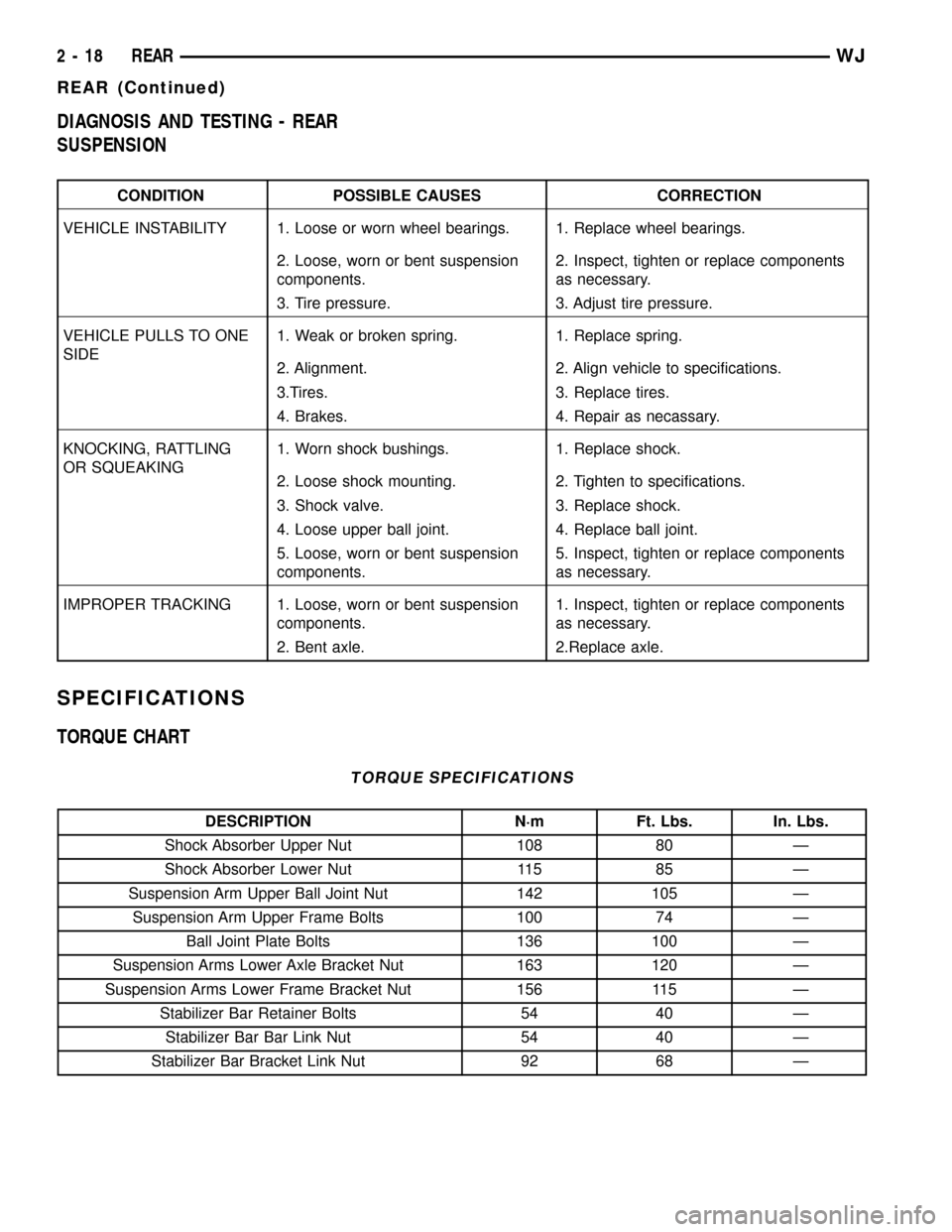
DIAGNOSIS AND TESTING - REAR
SUSPENSION
CONDITION POSSIBLE CAUSES CORRECTION
VEHICLE INSTABILITY 1. Loose or worn wheel bearings. 1. Replace wheel bearings.
2. Loose, worn or bent suspension
components.2. Inspect, tighten or replace components
as necessary.
3. Tire pressure. 3. Adjust tire pressure.
VEHICLE PULLS TO ONE
SIDE1. Weak or broken spring. 1. Replace spring.
2. Alignment. 2. Align vehicle to specifications.
3.Tires. 3. Replace tires.
4. Brakes. 4. Repair as necassary.
KNOCKING, RATTLING
OR SQUEAKING1. Worn shock bushings. 1. Replace shock.
2. Loose shock mounting. 2. Tighten to specifications.
3. Shock valve. 3. Replace shock.
4. Loose upper ball joint. 4. Replace ball joint.
5. Loose, worn or bent suspension
components.5. Inspect, tighten or replace components
as necessary.
IMPROPER TRACKING 1. Loose, worn or bent suspension
components.1. Inspect, tighten or replace components
as necessary.
2. Bent axle. 2.Replace axle.
SPECIFICATIONS
TORQUE CHART
TORQUE SPECIFICATIONS
DESCRIPTION N´m Ft. Lbs. In. Lbs.
Shock Absorber Upper Nut 108 80 Ð
Shock Absorber Lower Nut 115 85 Ð
Suspension Arm Upper Ball Joint Nut 142 105 Ð
Suspension Arm Upper Frame Bolts 100 74 Ð
Ball Joint Plate Bolts 136 100 Ð
Suspension Arms Lower Axle Bracket Nut 163 120 Ð
Suspension Arms Lower Frame Bracket Nut 156 115 Ð
Stabilizer Bar Retainer Bolts 54 40 Ð
Stabilizer Bar Bar Link Nut 54 40 Ð
Stabilizer Bar Bracket Link Nut 92 68 Ð
2 - 18 REARWJ
REAR (Continued)
Page 40 of 2199
SPECIAL TOOLS
REAR SUSPENSION
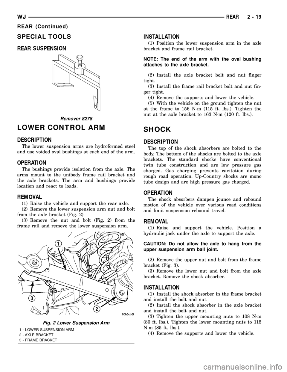
LOWER CONTROL ARM
DESCRIPTION
The lower suspension arms are hydroformed steel
and use voided oval bushings at each end of the arm.
OPERATION
The bushings provide isolation from the axle. The
arms mount to the unibody frame rail bracket and
the axle brackets. The arm and bushings provide
location and react to loads.
REMOVAL
(1) Raise the vehicle and support the rear axle.
(2) Remove the lower suspension arm nut and bolt
from the axle bracket (Fig. 2).
(3) Remove the nut and bolt (Fig. 2) from the
frame rail and remove the lower suspension arm.
INSTALLATION
(1) Position the lower suspension arm in the axle
bracket and frame rail bracket.
NOTE: The end of the arm with the oval bushing
attaches to the axle bracket.
(2) Install the axle bracket bolt and nut finger
tight.
(3) Install the frame rail bracket bolt and nut fin-
ger tight.
(4) Remove the supports and lower the vehicle.
(5) With the vehicle on the ground tighten the nut
at the frame to 156 N´m (115 ft. lbs.). Tighten the
nut at the axle bracket to 163 N´m (120 ft. lbs.).
SHOCK
DESCRIPTION
The top of the shock absorbers are bolted to the
body. The bottom of the shocks are bolted to the axle
brackets. The standard shocks have conventional
twin tube construction and are low pressure gas
charged. Gas charging prevents cavitation during
rough road operation. Up-Country shocks are mono
tube design and are high pressure gas charged.
OPERATION
The shock absorbers dampen jounce and rebound
motion of the vehicle over various road conditions
and limit suspension rebound travel.
REMOVAL
(1) Raise and support the vehicle. Position a
hydraulic jack under the axle to support the axle.
CAUTION: Do not allow the axle to hang from the
upper suspension arm ball joint.
(2) Remove the upper nut and bolt from the frame
bracket (Fig. 3).
(3) Remove the lower nut and bolt from the axle
bracket. Remove the shock absorber.
INSTALLATION
(1) Install the shock absorber in the frame bracket
and install the bolt and nut.
(2) Install the shock absorber in the axle bracket
and install the bolt and nut.
(3) Tighten the upper mounting nuts to 108 N´m
(80 ft. lbs.). Tighten the lower mounting nuts to 115
N´m (85 ft. lbs.).
(4) Remove the supports and lower the vehicle.
Remover 8278
Fig. 2 Lower Suspension Arm
1 - LOWER SUSPENSION ARM
2 - AXLE BRACKET
3 - FRAME BRACKET
WJREAR 2 - 19
REAR (Continued)
Page 42 of 2199
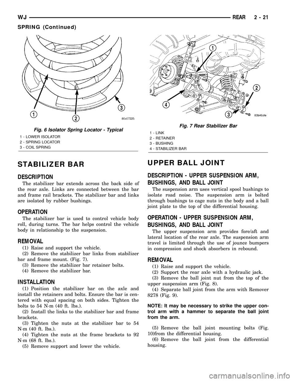
STABILIZER BAR
DESCRIPTION
The stabilizer bar extends across the back side of
the rear axle. Links are connected between the bar
and frame rail brackets. The stabilizer bar and links
are isolated by rubber bushings.
OPERATION
The stabilizer bar is used to control vehicle body
roll, during turns. The bar helps control the vehicle
body in relationship to the suspension.
REMOVAL
(1) Raise and support the vehicle.
(2) Remove the stabilizer bar links from stabilizer
bar and frame mount. (Fig. 7).
(3) Remove the stabilizer bar retainer bolts.
(4) Remove the stabilizer bar.
INSTALLATION
(1) Position the stabilizer bar on the axle and
install the retainers and bolts. Ensure the bar is cen-
tered with equal spacing on both sides. Tighten the
bolts to 54 N´m (40 ft. lbs.).
(2) Install the links to the stabilizer bar and frame
brackets.
(3) Tighten the nuts at the stabilizer bar to 54
N´m (40 ft. lbs.).
(4) Tighten the nuts at the frame brackets to 92
N´m (68 ft. lbs.).
(5) Remove support and lower the vehicle.
UPPER BALL JOINT
DESCRIPTION - UPPER SUSPENSION ARM,
BUSHINGS, AND BALL JOINT
The suspension arm uses vertical spool bushings to
isolate road noise. The suspension arm is bolted
through bushings to cage nuts in the body and a ball
joint plate to the top of the differential housing.
OPERATION - UPPER SUSPENSION ARM,
BUSHINGS, AND BALL JOINT
The upper suspension arm provides fore/aft and
lateral location of the rear axle. The suspension arm
travel is limited through the use of jounce bumpers
in compression and shock absorbers in rebound.
REMOVAL
(1) Raise and support the vehicle.
(2) Support the rear axle with a hydraulic jack.
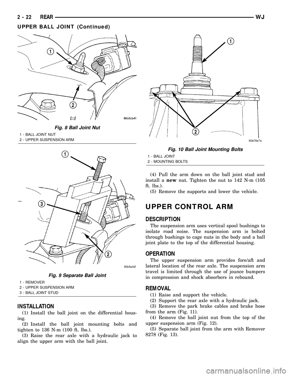
(3) Remove the ball joint nut from the top of the
upper suspension arm (Fig. 8).
(4) Separate ball joint from the arm with Remover
8278 (Fig. 9).
NOTE: It may be necessary to strike the upper con-
trol arm with a hammer to separate the ball joint
from the arm.
(5) Remove the ball joint mounting bolts (Fig.
10)from the differential housing.
(6) Remove the ball joint from the differential
housing.
Fig. 6 Isolator Spring Locator - Typical
1 - LOWER ISOLATOR
2 - SPRING LOCATOR
3 - COIL SPRING
Fig. 7 Rear Stabilizer Bar
1 - LINK
2 - RETAINER
3 - BUSHING
4 - STABILIZER BAR
WJREAR 2 - 21
SPRING (Continued)
Page 43 of 2199
INSTALLATION
(1) Install the ball joint on the differential hous-
ing.
(2) Install the ball joint mounting bolts and
tighten to 136 N´m (100 ft. lbs.).
(3) Raise the rear axle with a hydraulic jack to
align the upper arm with the ball joint.(4) Pull the arm down on the ball joint stud and
install anewnut. Tighten the nut to 142 N´m (105
ft. lbs.).
(5) Remove the supports and lower the vehicle.
UPPER CONTROL ARM
DESCRIPTION
The suspension arm uses vertical spool bushings to
isolate road noise. The suspension arm is bolted
through bushings to cage nuts in the body and a ball
joint plate to the top of the differential housing.
OPERATION
The upper suspension arm provides fore/aft and
lateral location of the rear axle. The suspension arm
travel is limited through the use of jounce bumpers
in compression and shock absorbers in rebound.
REMOVAL
(1) Raise and support the vehicle.
(2) Support the rear axle with a hydraulic jack.
(3) Remove the park brake cables and brake hose
from the arm (Fig. 11).
(4) Remove the ball joint nut from the top of the
upper suspension arm (Fig. 12).
(5) Separate ball joint from the arm with Remover
8278 (Fig. 13).
Fig. 8 Ball Joint Nut
1 - BALL JOINT NUT
2 - UPPER SUSPENSION ARM
Fig. 9 Separate Ball Joint
1 - REMOVER
2 - UPPER SUSPENSION ARM
3 - BALL JOINT STUD
Fig. 10 Ball Joint Mounting Bolts
1 - BALL JOINT
2 - MOUNTING BOLTS
2 - 22 REARWJ
UPPER BALL JOINT (Continued)
Page 186 of 2199
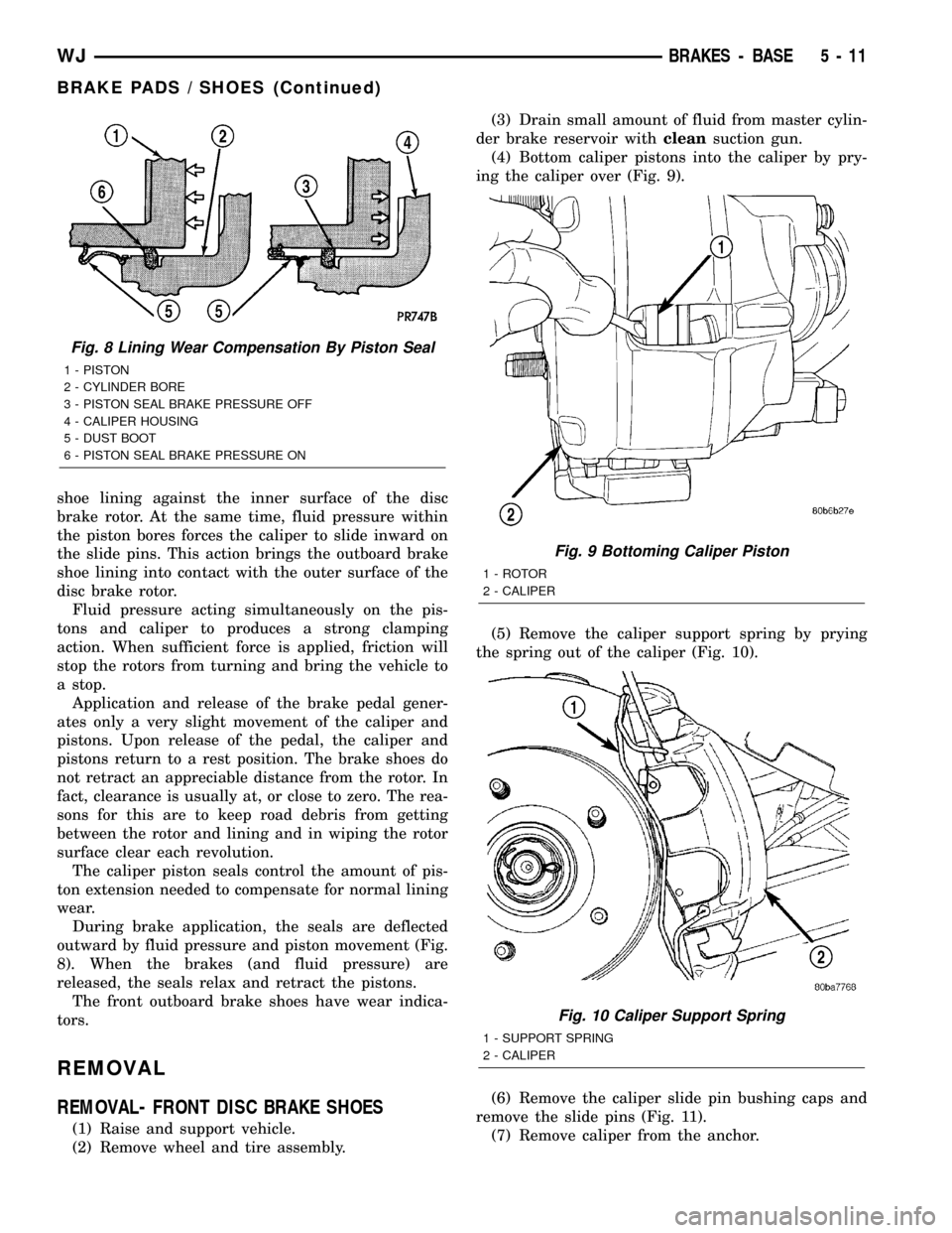
shoe lining against the inner surface of the disc
brake rotor. At the same time, fluid pressure within
the piston bores forces the caliper to slide inward on
the slide pins. This action brings the outboard brake
shoe lining into contact with the outer surface of the
disc brake rotor.
Fluid pressure acting simultaneously on the pis-
tons and caliper to produces a strong clamping
action. When sufficient force is applied, friction will
stop the rotors from turning and bring the vehicle to
a stop.
Application and release of the brake pedal gener-
ates only a very slight movement of the caliper and
pistons. Upon release of the pedal, the caliper and
pistons return to a rest position. The brake shoes do
not retract an appreciable distance from the rotor. In
fact, clearance is usually at, or close to zero. The rea-
sons for this are to keep road debris from getting
between the rotor and lining and in wiping the rotor
surface clear each revolution.
The caliper piston seals control the amount of pis-
ton extension needed to compensate for normal lining
wear.
During brake application, the seals are deflected
outward by fluid pressure and piston movement (Fig.
8). When the brakes (and fluid pressure) are
released, the seals relax and retract the pistons.
The front outboard brake shoes have wear indica-
tors.
REMOVAL
REMOVAL- FRONT DISC BRAKE SHOES
(1) Raise and support vehicle.
(2) Remove wheel and tire assembly.(3) Drain small amount of fluid from master cylin-
der brake reservoir withcleansuction gun.
(4) Bottom caliper pistons into the caliper by pry-
ing the caliper over (Fig. 9).
(5) Remove the caliper support spring by prying
the spring out of the caliper (Fig. 10).
(6) Remove the caliper slide pin bushing caps and
remove the slide pins (Fig. 11).
(7) Remove caliper from the anchor.
Fig. 8 Lining Wear Compensation By Piston Seal
1 - PISTON
2 - CYLINDER BORE
3 - PISTON SEAL BRAKE PRESSURE OFF
4 - CALIPER HOUSING
5 - DUST BOOT
6 - PISTON SEAL BRAKE PRESSURE ON
Fig. 9 Bottoming Caliper Piston
1 - ROTOR
2 - CALIPER
Fig. 10 Caliper Support Spring
1 - SUPPORT SPRING
2 - CALIPER
WJBRAKES - BASE 5 - 11
BRAKE PADS / SHOES (Continued)
Page 188 of 2199
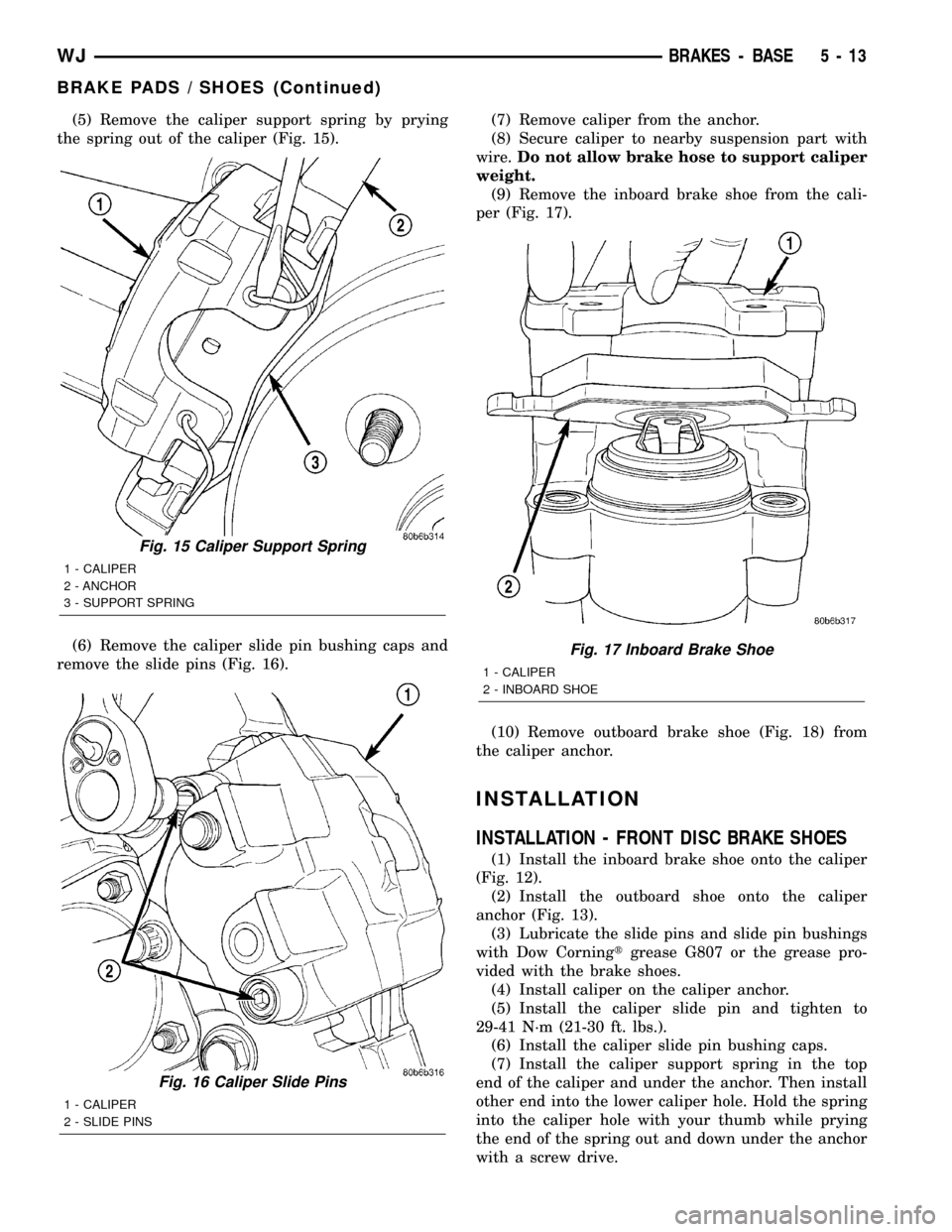
(5) Remove the caliper support spring by prying
the spring out of the caliper (Fig. 15).
(6) Remove the caliper slide pin bushing caps and
remove the slide pins (Fig. 16).(7) Remove caliper from the anchor.
(8) Secure caliper to nearby suspension part with
wire.Do not allow brake hose to support caliper
weight.
(9) Remove the inboard brake shoe from the cali-
per (Fig. 17).
(10) Remove outboard brake shoe (Fig. 18) from
the caliper anchor.
INSTALLATION
INSTALLATION - FRONT DISC BRAKE SHOES
(1) Install the inboard brake shoe onto the caliper
(Fig. 12).
(2) Install the outboard shoe onto the caliper
anchor (Fig. 13).
(3) Lubricate the slide pins and slide pin bushings
with Dow Corningtgrease G807 or the grease pro-
vided with the brake shoes.
(4) Install caliper on the caliper anchor.
(5) Install the caliper slide pin and tighten to
29-41 N´m (21-30 ft. lbs.).
(6) Install the caliper slide pin bushing caps.
(7) Install the caliper support spring in the top
end of the caliper and under the anchor. Then install
other end into the lower caliper hole. Hold the spring
into the caliper hole with your thumb while prying
the end of the spring out and down under the anchor
with a screw drive.
Fig. 15 Caliper Support Spring
1 - CALIPER
2 - ANCHOR
3 - SUPPORT SPRING
Fig. 16 Caliper Slide Pins
1 - CALIPER
2 - SLIDE PINS
Fig. 17 Inboard Brake Shoe
1 - CALIPER
2 - INBOARD SHOE
WJBRAKES - BASE 5 - 13
BRAKE PADS / SHOES (Continued)
Page 189 of 2199
(8) Install wheel and tire assembly.
(9) Remove support and lower vehicle.
(10) Pump brake pedal until caliper pistons and
brake shoes are seated and a firm brake pedal is
obtained.
(11) Fill brake fluid.
INSTALLATION - REAR DISC BRAKE SHOES
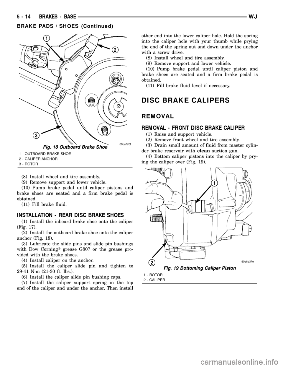
(1) Install the inboard brake shoe onto the caliper
(Fig. 17).
(2) Install the outboard brake shoe onto the caliper
anchor (Fig. 18).
(3) Lubricate the slide pins and slide pin bushings
with Dow Corningtgrease G807 or the grease pro-
vided with the brake shoes.
(4) Install caliper on the anchor.
(5) Install the caliper slide pin and tighten to
29-41 N´m (21-30 ft. lbs.).
(6) Install the caliper slide pin bushing caps.
(7) Install the caliper support spring in the top
end of the caliper and under the anchor. Then installother end into the lower caliper hole. Hold the spring
into the caliper hole with your thumb while prying
the end of the spring out and down under the anchor
with a screw drive.
(8) Install wheel and tire assembly.
(9) Remove support and lower vehicle.
(10) Pump brake pedal until caliper piston and
brake shoes are seated and a firm brake pedal is
obtained.
(11) Fill brake fluid level if necessary.
DISC BRAKE CALIPERS
REMOVAL
REMOVAL - FRONT DISC BRAKE CALIPER
(1) Raise and support vehicle.
(2) Remove front wheel and tire assembly.
(3) Drain small amount of fluid from master cylin-
der brake reservoir withcleansuction gun.
(4) Bottom caliper pistons into the caliper by pry-
ing the caliper over (Fig. 19).
Fig. 18 Outboard Brake Shoe
1 - OUTBOARD BRAKE SHOE
2 - CALIPER ANCHOR
3 - ROTOR
Fig. 19 Bottoming Caliper Piston
1 - ROTOR
2 - CALIPER
5 - 14 BRAKES - BASEWJ
BRAKE PADS / SHOES (Continued)
Page 190 of 2199
(5) Remove brake hose banjo bolt and gasket
washers. Discard gasket washers.
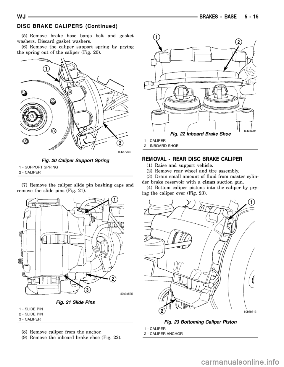
(6) Remove the caliper support spring by prying
the spring out of the caliper (Fig. 20).
(7) Remove the caliper slide pin bushing caps and
remove the slide pins (Fig. 21).
(8) Remove caliper from the anchor.
(9) Remove the inboard brake shoe (Fig. 22).
REMOVAL - REAR DISC BRAKE CALIPER
(1) Raise and support vehicle.
(2) Remove rear wheel and tire assembly.
(3) Drain small amount of fluid from master cylin-
der brake reservoir with acleansuction gun.
(4) Bottom caliper pistons into the caliper by pry-
ing the caliper over (Fig. 23).
Fig. 20 Caliper Support Spring
1 - SUPPORT SPRING
2 - CALIPER
Fig. 21 Slide Pins
1 - SLIDE PIN
2 - SLIDE PIN
3 - CALIPER
Fig. 22 Inboard Brake Shoe
1 - CALIPER
2 - INBOARD SHOE
Fig. 23 Bottoming Caliper Piston
1 - CALIPER
2 - CALIPER ANCHOR
WJBRAKES - BASE 5 - 15
DISC BRAKE CALIPERS (Continued)
Page 191 of 2199
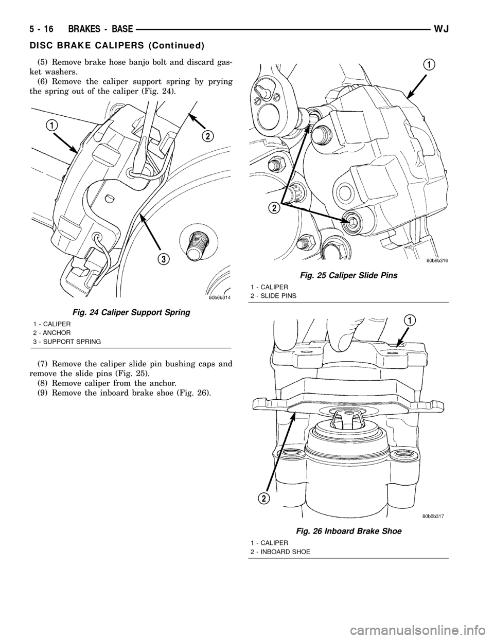
(5) Remove brake hose banjo bolt and discard gas-
ket washers.
(6) Remove the caliper support spring by prying
the spring out of the caliper (Fig. 24).
(7) Remove the caliper slide pin bushing caps and
remove the slide pins (Fig. 25).
(8) Remove caliper from the anchor.
(9) Remove the inboard brake shoe (Fig. 26).
Fig. 24 Caliper Support Spring
1 - CALIPER
2 - ANCHOR
3 - SUPPORT SPRING
Fig. 25 Caliper Slide Pins
1 - CALIPER
2 - SLIDE PINS
Fig. 26 Inboard Brake Shoe
1 - CALIPER
2 - INBOARD SHOE
5 - 16 BRAKES - BASEWJ
DISC BRAKE CALIPERS (Continued)
Page 193 of 2199
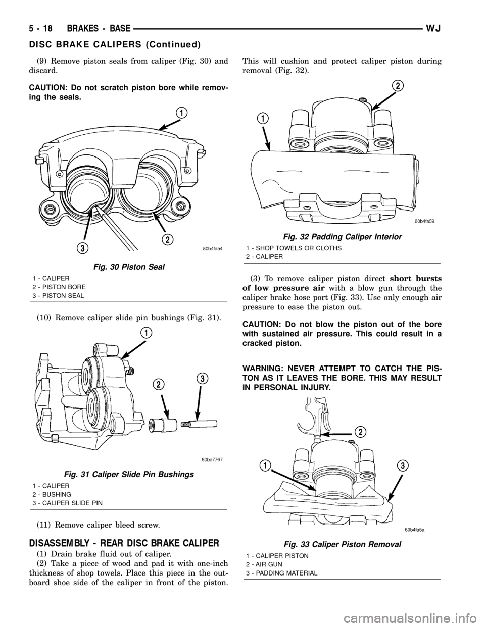
(9) Remove piston seals from caliper (Fig. 30) and
discard.
CAUTION: Do not scratch piston bore while remov-
ing the seals.
(10) Remove caliper slide pin bushings (Fig. 31).
(11) Remove caliper bleed screw.
DISASSEMBLY - REAR DISC BRAKE CALIPER
(1) Drain brake fluid out of caliper.
(2) Take a piece of wood and pad it with one-inch
thickness of shop towels. Place this piece in the out-
board shoe side of the caliper in front of the piston.This will cushion and protect caliper piston during
removal (Fig. 32).
(3) To remove caliper piston directshort bursts
of low pressure airwith a blow gun through the
caliper brake hose port (Fig. 33). Use only enough air
pressure to ease the piston out.
CAUTION: Do not blow the piston out of the bore
with sustained air pressure. This could result in a
cracked piston.
WARNING: NEVER ATTEMPT TO CATCH THE PIS-
TON AS IT LEAVES THE BORE. THIS MAY RESULT
IN PERSONAL INJURY.
Fig. 30 Piston Seal
1 - CALIPER
2 - PISTON BORE
3 - PISTON SEAL
Fig. 31 Caliper Slide Pin Bushings
1 - CALIPER
2 - BUSHING
3 - CALIPER SLIDE PIN
Fig. 32 Padding Caliper Interior
1 - SHOP TOWELS OR CLOTHS
2 - CALIPER
Fig. 33 Caliper Piston Removal
1 - CALIPER PISTON
2 - AIR GUN
3 - PADDING MATERIAL
5 - 18 BRAKES - BASEWJ
DISC BRAKE CALIPERS (Continued)