Bus JEEP GRAND CHEROKEE 2002 WJ / 2.G Workshop Manual
[x] Cancel search | Manufacturer: JEEP, Model Year: 2002, Model line: GRAND CHEROKEE, Model: JEEP GRAND CHEROKEE 2002 WJ / 2.GPages: 2199, PDF Size: 76.01 MB
Page 15 of 2199
becomes contaminated, drain, flush, and replace with
fresh properly mixed coolant solution.
CAUTION: Do not use coolant additives that are
claimed to improve engine cooling.
ENGINE OIL
WARNING: NEW OR USED ENGINE OIL CAN BE
IRRITATING TO THE SKIN. AVOID PROLONGED OR
REPEATED SKIN CONTACT WITH ENGINE OIL.
CONTAMINANTS IN USED ENGINE OIL, CAUSED BY
INTERNAL COMBUSTION, CAN BE HAZARDOUS TO
YOUR HEALTH. THOROUGHLY WASH EXPOSED
SKIN WITH SOAP AND WATER. DO NOT WASH
SKIN WITH GASOLINE, DIESEL FUEL, THINNER, OR
SOLVENTS, HEALTH PROBLEMS CAN RESULT. DO
NOT POLLUTE, DISPOSE OF USED ENGINE OIL
PROPERLY. CONTACT YOUR DEALER OR GOVERN-
MENT AGENCY FOR LOCATION OF COLLECTION
CENTER IN YOUR AREA.
API SERVICE GRADE CERTIFIED
Use an engine oil that is API Service Grade Certi-
fied. MOPARtprovides engine oils that conform to
this service grade.
SAE VISCOSITY
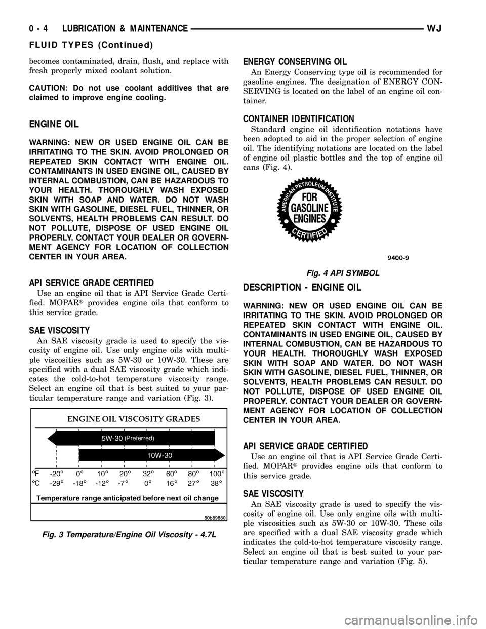
An SAE viscosity grade is used to specify the vis-
cosity of engine oil. Use only engine oils with multi-
ple viscosities such as 5W-30 or 10W-30. These are
specified with a dual SAE viscosity grade which indi-
cates the cold-to-hot temperature viscosity range.
Select an engine oil that is best suited to your par-
ticular temperature range and variation (Fig. 3).
ENERGY CONSERVING OIL
An Energy Conserving type oil is recommended for
gasoline engines. The designation of ENERGY CON-
SERVING is located on the label of an engine oil con-
tainer.
CONTAINER IDENTIFICATION
Standard engine oil identification notations have
been adopted to aid in the proper selection of engine
oil. The identifying notations are located on the label
of engine oil plastic bottles and the top of engine oil
cans (Fig. 4).
DESCRIPTION - ENGINE OIL
WARNING: NEW OR USED ENGINE OIL CAN BE
IRRITATING TO THE SKIN. AVOID PROLONGED OR
REPEATED SKIN CONTACT WITH ENGINE OIL.
CONTAMINANTS IN USED ENGINE OIL, CAUSED BY
INTERNAL COMBUSTION, CAN BE HAZARDOUS TO
YOUR HEALTH. THOROUGHLY WASH EXPOSED
SKIN WITH SOAP AND WATER. DO NOT WASH
SKIN WITH GASOLINE, DIESEL FUEL, THINNER, OR
SOLVENTS, HEALTH PROBLEMS CAN RESULT. DO
NOT POLLUTE, DISPOSE OF USED ENGINE OIL
PROPERLY. CONTACT YOUR DEALER OR GOVERN-
MENT AGENCY FOR LOCATION OF COLLECTION
CENTER IN YOUR AREA.
API SERVICE GRADE CERTIFIED
Use an engine oil that is API Service Grade Certi-
fied. MOPARtprovides engine oils that conform to
this service grade.
SAE VISCOSITY
An SAE viscosity grade is used to specify the vis-
cosity of engine oil. Use only engine oils with multi-
ple viscosities such as 5W-30 or 10W-30. These oils
are specified with a dual SAE viscosity grade which
indicates the cold-to-hot temperature viscosity range.
Select an engine oil that is best suited to your par-
ticular temperature range and variation (Fig. 5).
Fig. 3 Temperature/Engine Oil Viscosity - 4.7L
Fig. 4 API SYMBOL
0 - 4 LUBRICATION & MAINTENANCEWJ
FLUID TYPES (Continued)
Page 23 of 2199
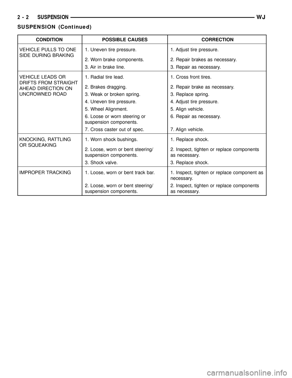
CONDITION POSSIBLE CAUSES CORRECTION
VEHICLE PULLS TO ONE
SIDE DURING BRAKING1. Uneven tire pressure. 1. Adjust tire pressure.
2. Worn brake components. 2. Repair brakes as necessary.
3. Air in brake line. 3. Repair as necessary.
VEHICLE LEADS OR
DRIFTS FROM STRAIGHT
AHEAD DIRECTION ON
UNCROWNED ROAD1. Radial tire lead. 1. Cross front tires.
2. Brakes dragging. 2. Repair brake as necessary.
3. Weak or broken spring. 3. Replace spring.
4. Uneven tire pressure. 4. Adjust tire pressure.
5. Wheel Alignment. 5. Align vehicle.
6. Loose or worn steering or
suspension components.6. Repair as necessary.
7. Cross caster out of spec. 7. Align vehicle.
KNOCKING, RATTLING
OR SQUEAKING1. Worn shock bushings. 1. Replace shock.
2. Loose, worn or bent steering/
suspension components.2. Inspect, tighten or replace components
as necessary.
3. Shock valve. 3. Replace shock.
IMPROPER TRACKING 1. Loose, worn or bent track bar. 1. Inspect, tighten or replace component as
necessary.
2. Loose, worn or bent steering/
suspension components.2. Inspect, tighten or replace components
as necessary.
2 - 2 SUSPENSIONWJ
SUSPENSION (Continued)
Page 24 of 2199
WHEEL ALIGNMENT
TABLE OF CONTENTS
page page
WHEEL ALIGNMENT
DESCRIPTION..........................3
OPERATION............................3
STANDARD PROCEDURE
STANDARD PROCEDURE - CAMBER.......3STANDARD PROCEDURE - CASTER.......4
STANDARD PROCEDURE - TOE POSITION . . 4
SPECIFICATIONS
ALIGNMENT..........................5
WHEEL ALIGNMENT
DESCRIPTION
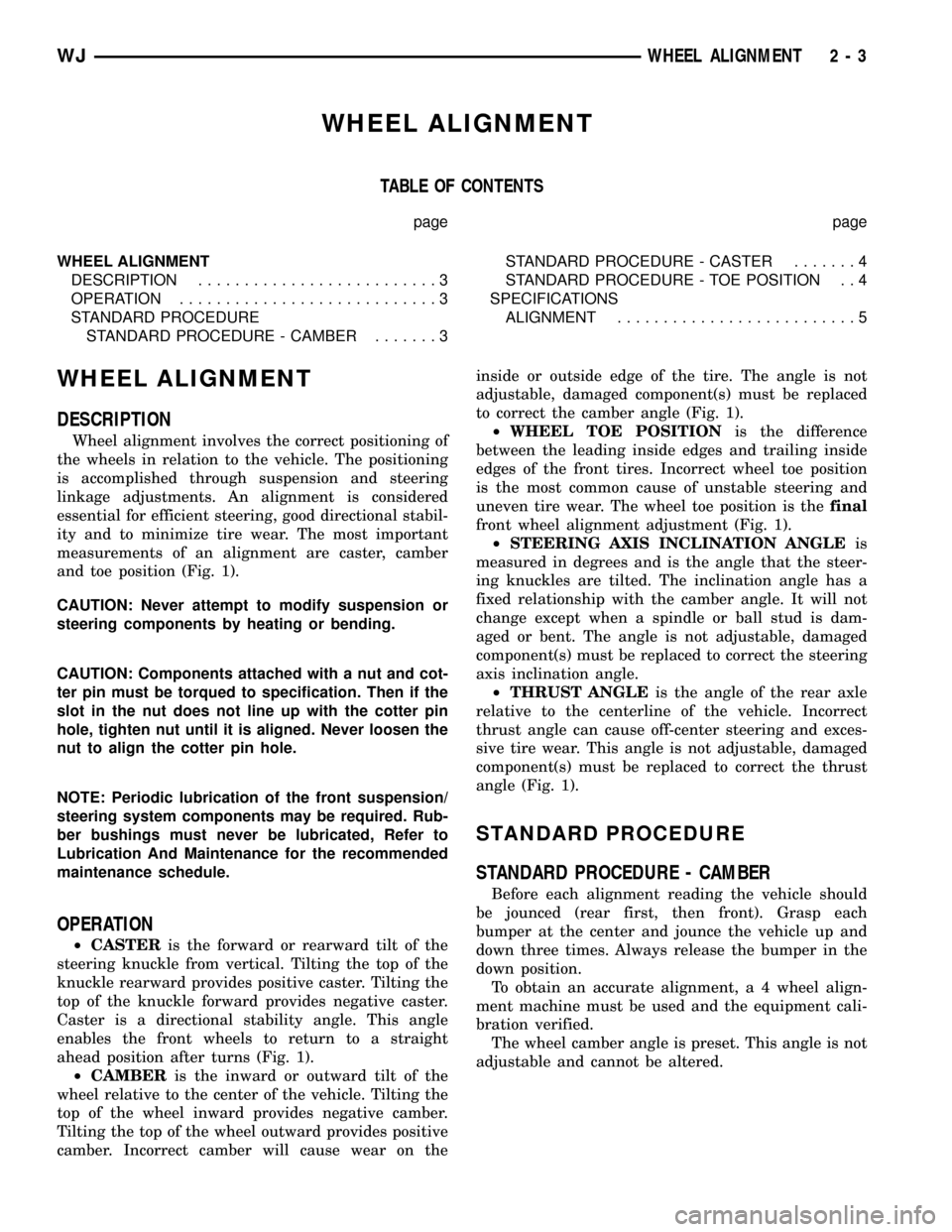
Wheel alignment involves the correct positioning of
the wheels in relation to the vehicle. The positioning
is accomplished through suspension and steering
linkage adjustments. An alignment is considered
essential for efficient steering, good directional stabil-
ity and to minimize tire wear. The most important
measurements of an alignment are caster, camber
and toe position (Fig. 1).
CAUTION: Never attempt to modify suspension or
steering components by heating or bending.
CAUTION: Components attached with a nut and cot-
ter pin must be torqued to specification. Then if the
slot in the nut does not line up with the cotter pin
hole, tighten nut until it is aligned. Never loosen the
nut to align the cotter pin hole.
NOTE: Periodic lubrication of the front suspension/
steering system components may be required. Rub-
ber bushings must never be lubricated, Refer to
Lubrication And Maintenance for the recommended
maintenance schedule.
OPERATION
²CASTERis the forward or rearward tilt of the
steering knuckle from vertical. Tilting the top of the
knuckle rearward provides positive caster. Tilting the
top of the knuckle forward provides negative caster.
Caster is a directional stability angle. This angle
enables the front wheels to return to a straight
ahead position after turns (Fig. 1).
²CAMBERis the inward or outward tilt of the
wheel relative to the center of the vehicle. Tilting the
top of the wheel inward provides negative camber.
Tilting the top of the wheel outward provides positive
camber. Incorrect camber will cause wear on theinside or outside edge of the tire. The angle is not
adjustable, damaged component(s) must be replaced
to correct the camber angle (Fig. 1).
²WHEEL TOE POSITIONis the difference
between the leading inside edges and trailing inside
edges of the front tires. Incorrect wheel toe position
is the most common cause of unstable steering and
uneven tire wear. The wheel toe position is thefinal
front wheel alignment adjustment (Fig. 1).
²STEERING AXIS INCLINATION ANGLEis
measured in degrees and is the angle that the steer-
ing knuckles are tilted. The inclination angle has a
fixed relationship with the camber angle. It will not
change except when a spindle or ball stud is dam-
aged or bent. The angle is not adjustable, damaged
component(s) must be replaced to correct the steering
axis inclination angle.
²THRUST ANGLEis the angle of the rear axle
relative to the centerline of the vehicle. Incorrect
thrust angle can cause off-center steering and exces-
sive tire wear. This angle is not adjustable, damaged
component(s) must be replaced to correct the thrust
angle (Fig. 1).
STANDARD PROCEDURE
STANDARD PROCEDURE - CAMBER
Before each alignment reading the vehicle should
be jounced (rear first, then front). Grasp each
bumper at the center and jounce the vehicle up and
down three times. Always release the bumper in the
down position.
To obtain an accurate alignment, a 4 wheel align-
ment machine must be used and the equipment cali-
bration verified.
The wheel camber angle is preset. This angle is not
adjustable and cannot be altered.
WJWHEEL ALIGNMENT 2 - 3
Page 27 of 2199
FRONT
TABLE OF CONTENTS
page page
FRONT
DESCRIPTION..........................6
STANDARD PROCEDURE - SERVICE
WARNINGS AND CAUTIONS..............6
SPECIFICATIONS
TORQUE CHART......................7
SPECIAL TOOLS
FRONT SUSPENSION...................8
BUSHINGS
REMOVAL.............................9
INSTALLATION..........................9
HUB / BEARING
DESCRIPTION..........................9
OPERATION............................9
REMOVAL.............................9
INSTALLATION.........................10
KNUCKLE
DESCRIPTION.........................10
OPERATION...........................10
REMOVAL - STEERING KNUCKLE..........10
INSTALLATION.........................10
LOWER BALL JOINT
REMOVAL.............................11
LOWER CONTROL ARM
DESCRIPTION.........................11
OPERATION...........................11
REMOVAL.............................11
INSTALLATION.........................11SHOCK
DESCRIPTION.........................12
OPERATION...........................12
REMOVAL.............................12
INSTALLATION.........................12
SPRING
DESCRIPTION.........................12
OPERATION...........................13
REMOVAL.............................13
INSTALLATION.........................13
STABILIZER BAR
DESCRIPTION.........................14
OPERATION...........................14
REMOVAL.............................14
INSTALLATION.........................14
TRACK BAR
DESCRIPTION.........................14
OPERATION...........................14
REMOVAL.............................14
INSTALLATION.........................14
UPPER BALL JOINT
REMOVAL.............................15
UPPER CONTROL ARM
DESCRIPTION.........................16
OPERATION...........................16
REMOVAL.............................16
INSTALLATION.........................16
FRONT
DESCRIPTION
The front suspension (Fig. 1) is a link/coil design
comprised of :
²Drive axle
²Shock absorbers
²Coil springs
²Upper and lower suspension arms
²Stabilizer bar
²Track bar
²Jounce bumpers
CAUTION: Components attached with a nut and cot-
ter pin must be torqued to specification. Then if the
slot in the nut does not line up with the cotter pin
hole, tighten nut until it is aligned. Never loosen the
nut to align the cotter pin hole.CAUTION: Suspension components with rubber
bushings must be tightened with the vehicle at nor-
mal ride height. It is important to have the springs
supporting the weight of the vehicle when the fas-
teners are torqued. If springs are not at their normal
ride position, vehicle ride comfort will be affected
and cause premature bushing wear.
STANDARD PROCEDURE - SERVICE
WARNINGS AND CAUTIONS
CAUTION: Suspension components with rubber
bushings must be tightened with the vehicle at nor-
mal ride height. It is important to have the springs
supporting the weight of the vehicle when the fas-
teners are torqued. If springs are not at their normal
ride position, vehicle ride comfort will be affected
and cause premature bushing wear.
2 - 6 FRONTWJ
Page 29 of 2199
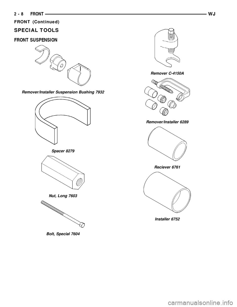
SPECIAL TOOLS
FRONT SUSPENSION
Remover/Installer Suspension Bushing 7932
Spacer 8279
Nut, Long 7603
Bolt, Special 7604
Remover C-4150A
Remover/Installer 6289
Reciever 6761
Installer 6752
2 - 8 FRONTWJ
FRONT (Continued)
Page 30 of 2199
BUSHINGS
REMOVAL
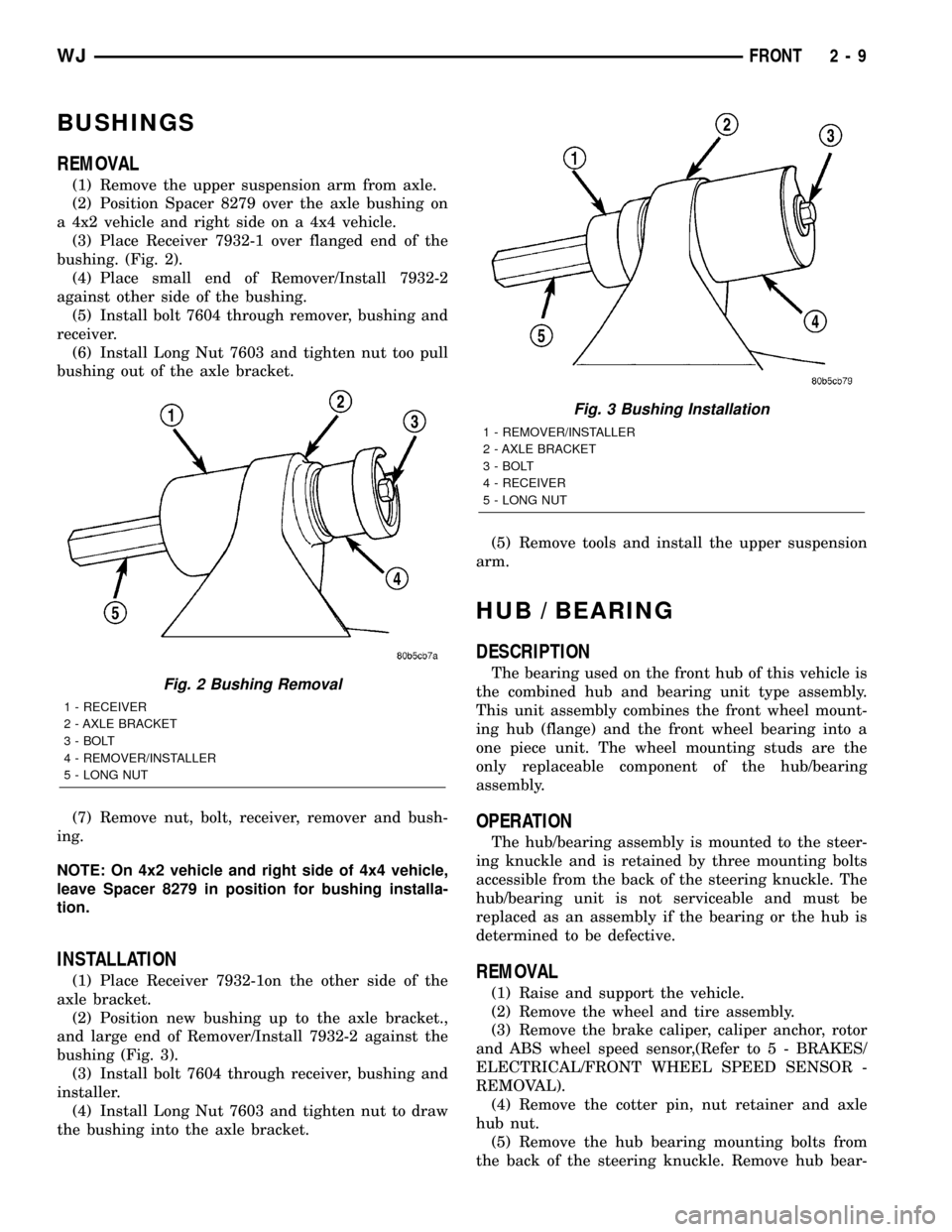
(1) Remove the upper suspension arm from axle.
(2) Position Spacer 8279 over the axle bushing on
a 4x2 vehicle and right side on a 4x4 vehicle.
(3) Place Receiver 7932-1 over flanged end of the
bushing. (Fig. 2).
(4) Place small end of Remover/Install 7932-2
against other side of the bushing.
(5) Install bolt 7604 through remover, bushing and
receiver.
(6) Install Long Nut 7603 and tighten nut too pull
bushing out of the axle bracket.
(7) Remove nut, bolt, receiver, remover and bush-
ing.
NOTE: On 4x2 vehicle and right side of 4x4 vehicle,
leave Spacer 8279 in position for bushing installa-
tion.
INSTALLATION
(1) Place Receiver 7932-1on the other side of the
axle bracket.
(2) Position new bushing up to the axle bracket.,
and large end of Remover/Install 7932-2 against the
bushing (Fig. 3).
(3) Install bolt 7604 through receiver, bushing and
installer.
(4) Install Long Nut 7603 and tighten nut to draw
the bushing into the axle bracket.(5) Remove tools and install the upper suspension
arm.
HUB / BEARING
DESCRIPTION
The bearing used on the front hub of this vehicle is
the combined hub and bearing unit type assembly.
This unit assembly combines the front wheel mount-
ing hub (flange) and the front wheel bearing into a
one piece unit. The wheel mounting studs are the
only replaceable component of the hub/bearing
assembly.
OPERATION
The hub/bearing assembly is mounted to the steer-
ing knuckle and is retained by three mounting bolts
accessible from the back of the steering knuckle. The
hub/bearing unit is not serviceable and must be
replaced as an assembly if the bearing or the hub is
determined to be defective.
REMOVAL
(1) Raise and support the vehicle.
(2) Remove the wheel and tire assembly.
(3) Remove the brake caliper, caliper anchor, rotor
and ABS wheel speed sensor,(Refer to 5 - BRAKES/
ELECTRICAL/FRONT WHEEL SPEED SENSOR -
REMOVAL).
(4) Remove the cotter pin, nut retainer and axle
hub nut.
(5) Remove the hub bearing mounting bolts from
the back of the steering knuckle. Remove hub bear-
Fig. 2 Bushing Removal
1 - RECEIVER
2 - AXLE BRACKET
3 - BOLT
4 - REMOVER/INSTALLER
5 - LONG NUT
Fig. 3 Bushing Installation
1 - REMOVER/INSTALLER
2 - AXLE BRACKET
3 - BOLT
4 - RECEIVER
5 - LONG NUT
WJFRONT 2 - 9
Page 32 of 2199
LOWER BALL JOINT
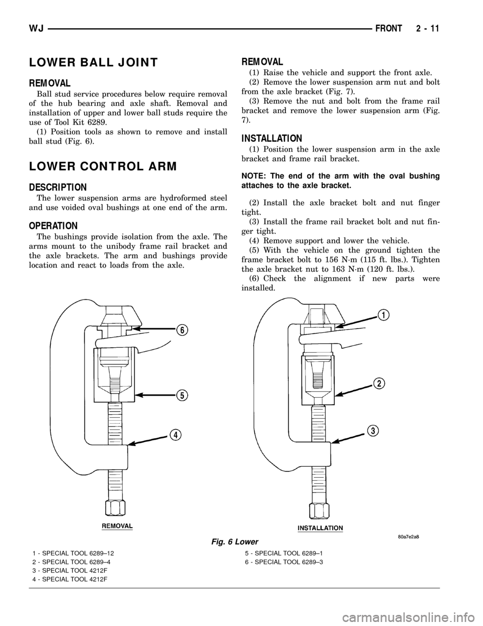
REMOVAL
Ball stud service procedures below require removal
of the hub bearing and axle shaft. Removal and
installation of upper and lower ball studs require the
use of Tool Kit 6289.
(1) Position tools as shown to remove and install
ball stud (Fig. 6).
LOWER CONTROL ARM
DESCRIPTION
The lower suspension arms are hydroformed steel
and use voided oval bushings at one end of the arm.
OPERATION
The bushings provide isolation from the axle. The
arms mount to the unibody frame rail bracket and
the axle brackets. The arm and bushings provide
location and react to loads from the axle.
REMOVAL
(1) Raise the vehicle and support the front axle.
(2) Remove the lower suspension arm nut and bolt
from the axle bracket (Fig. 7).
(3) Remove the nut and bolt from the frame rail
bracket and remove the lower suspension arm (Fig.
7).
INSTALLATION
(1) Position the lower suspension arm in the axle
bracket and frame rail bracket.
NOTE: The end of the arm with the oval bushing
attaches to the axle bracket.
(2) Install the axle bracket bolt and nut finger
tight.
(3) Install the frame rail bracket bolt and nut fin-
ger tight.
(4) Remove support and lower the vehicle.
(5) With the vehicle on the ground tighten the
frame bracket bolt to 156 N´m (115 ft. lbs.). Tighten
the axle bracket nut to 163 N´m (120 ft. lbs.).
(6) Check the alignment if new parts were
installed.
Fig. 6 Lower
1 - SPECIAL TOOL 6289±12
2 - SPECIAL TOOL 6289±4
3 - SPECIAL TOOL 4212F
4 - SPECIAL TOOL 4212F5 - SPECIAL TOOL 6289±1
6 - SPECIAL TOOL 6289±3
WJFRONT 2 - 11
Page 35 of 2199
(6) Install the track bar to the axle bracket and
install the mounting bolt.
NOTE: It may be necessary to pry the axle assem-
bly over to install the track bar bolt.
(7) Remove the hydraulic jack from under the
vehicle.
(8) Tighten all suspension components to proper
torque.
(9) Install the wheel and tire assemblies.
(10) Remove support and lower vehicle.
STABILIZER BAR
DESCRIPTION
The bar extends across the front underside of the
chassis and is mounted to the frame rails. Links are
connected from the bar to the axle brackets. The sta-
bilizer bar and links are isolated by rubber bushings.
OPERATION
The stabilizer bar is used to control vehicle body
roll during turns. The spring steel bar helps to con-
trol the vehicle body in relationship to the suspen-
sion.
REMOVAL
(1) Raise and support the vehicle.
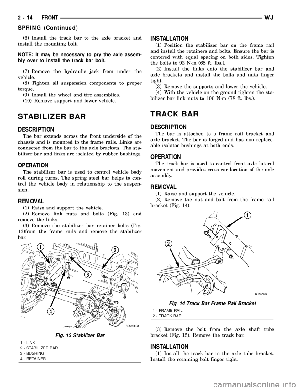
(2) Remove link nuts and bolts (Fig. 13) and
remove the links.
(3) Remove the stabilizer bar retainer bolts (Fig.
13)from the frame rails and remove the stabilizer
bar.
INSTALLATION
(1) Position the stabilizer bar on the frame rail
and install the retainers and bolts. Ensure the bar is
centered with equal spacing on both sides. Tighten
the bolts to 92 N´m (68 ft. lbs.).
(2) Install the links onto the stabilizer bar and
axle brackets and install the bolts and nuts finger
tight.
(3) Remove the supports and lower the vehicle.
(4) With the vehicle on the ground tighten the sta-
bilizer bar link nuts to 106 N´m (78 ft. lbs.).
TRACK BAR
DESCRIPTION
The bar is attached to a frame rail bracket and
axle bracket. The bar is forged and has non replace-
able isolator bushings at both ends.
OPERATION
The track bar is used to control front axle lateral
movement and provides cross car location of the axle
assembly.
REMOVAL
(1) Raise and support the vehicle.
(2) Remove the nut and bolt from the frame rail
bracket (Fig. 14).
(3) Remove the bolt from the axle shaft tube
bracket (Fig. 15). Remove the track bar.
INSTALLATION
(1) Install the track bar to the axle tube bracket.
Install the retaining bolt finger tight.
Fig. 13 Stabilizer Bar
1 - LINK
2 - STABILIZER BAR
3 - BUSHING
4 - RETAINER
Fig. 14 Track Bar Frame Rail Bracket
1 - FRAME RAIL
2 - TRACK BAR
2 - 14 FRONTWJ
SPRING (Continued)
Page 37 of 2199
UPPER CONTROL ARM
DESCRIPTION
The upper suspension arms are hydroformed steel
and use rubber bushings at each end of the arm.
OPERATION
The arms mount to the unibody frame rail bracket
and the axle brackets. The arm and bushings provide
location and react to loads from the axle. The bush-
ings provide isolation from the axle.
REMOVAL
(1) Raise vehicle and support the axle.
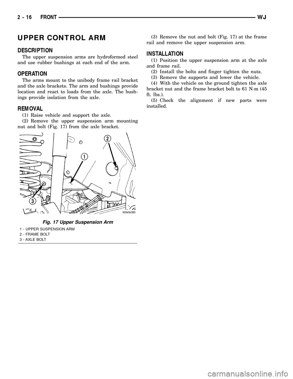
(2) Remove the upper suspension arm mounting
nut and bolt (Fig. 17) from the axle bracket.(3) Remove the nut and bolt (Fig. 17) at the frame
rail and remove the upper suspension arm.
INSTALLATION
(1) Position the upper suspension arm at the axle
and frame rail.
(2) Install the bolts and finger tighten the nuts.
(3) Remove the supports and lower the vehicle.
(4) With the vehicle on the ground tighten the axle
bracket nut and the frame bracket bolt to 61 N´m (45
ft. lbs.).
(5) Check the alignment if new parts were
installed.
Fig. 17 Upper Suspension Arm
1 - UPPER SUSPENSION ARM
2 - FRAME BOLT
3 - AXLE BOLT
2 - 16 FRONTWJ
Page 38 of 2199
REAR
TABLE OF CONTENTS
page page
REAR
DESCRIPTION.........................17
WARNING.............................17
DIAGNOSIS AND TESTING - REAR
SUSPENSION........................18
SPECIFICATIONS
TORQUE CHART......................18
SPECIAL TOOLS
REAR SUSPENSION...................19
LOWER CONTROL ARM
DESCRIPTION.........................19
OPERATION...........................19
REMOVAL.............................19
INSTALLATION.........................19
SHOCK
DESCRIPTION.........................19
OPERATION...........................19
REMOVAL.............................19
INSTALLATION.........................19
SPRING
DESCRIPTION.........................20OPERATION...........................20
REMOVAL.............................20
INSTALLATION.........................20
STABILIZER BAR
DESCRIPTION.........................21
OPERATION...........................21
REMOVAL.............................21
INSTALLATION.........................21
UPPER BALL JOINT
DESCRIPTION - UPPER SUSPENSION ARM,
BUSHINGS, AND BALL JOINT............21
OPERATION - UPPER SUSPENSION ARM,
BUSHINGS, AND BALL JOINT............21
REMOVAL.............................21
INSTALLATION.........................22
UPPER CONTROL ARM
DESCRIPTION.........................22
OPERATION...........................22
REMOVAL.............................22
INSTALLATION.........................23
REAR
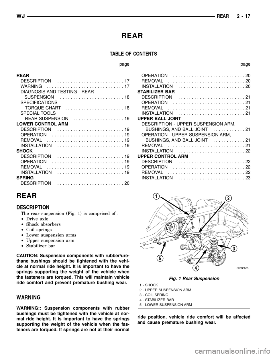
DESCRIPTION
The rear suspension (Fig. 1) is comprised of :
²Drive axle
²Shock absorbers
²Coil springs
²Lower suspension arms
²Upper suspension arm
²Stabilizer bar
CAUTION: Suspension components with rubber/ure-
thane bushings should be tightened with the vehi-
cle at normal ride height. It is important to have the
springs supporting the weight of the vehicle when
the fasteners are torqued. This will maintain vehicle
ride comfort and prevent premature bushing wear.
WARNING
WARNING:: Suspension components with rubber
bushings must be tightened with the vehicle at nor-
mal ride height. It is important to have the springs
supporting the weight of the vehicle when the fas-
teners are torqued. If springs are not at their normalride position, vehicle ride comfort will be affected
and cause premature bushing wear.
Fig. 1 Rear Suspension
1 - SHOCK
2 - UPPER SUSPENSION ARM
3 - COIL SPRING
4 - STABILIZER BAR
5 - LOWER SUSPENSION ARM
WJREAR 2 - 17