Control arm JEEP GRAND CHEROKEE 2002 WJ / 2.G User Guide
[x] Cancel search | Manufacturer: JEEP, Model Year: 2002, Model line: GRAND CHEROKEE, Model: JEEP GRAND CHEROKEE 2002 WJ / 2.GPages: 2199, PDF Size: 76.01 MB
Page 116 of 2199
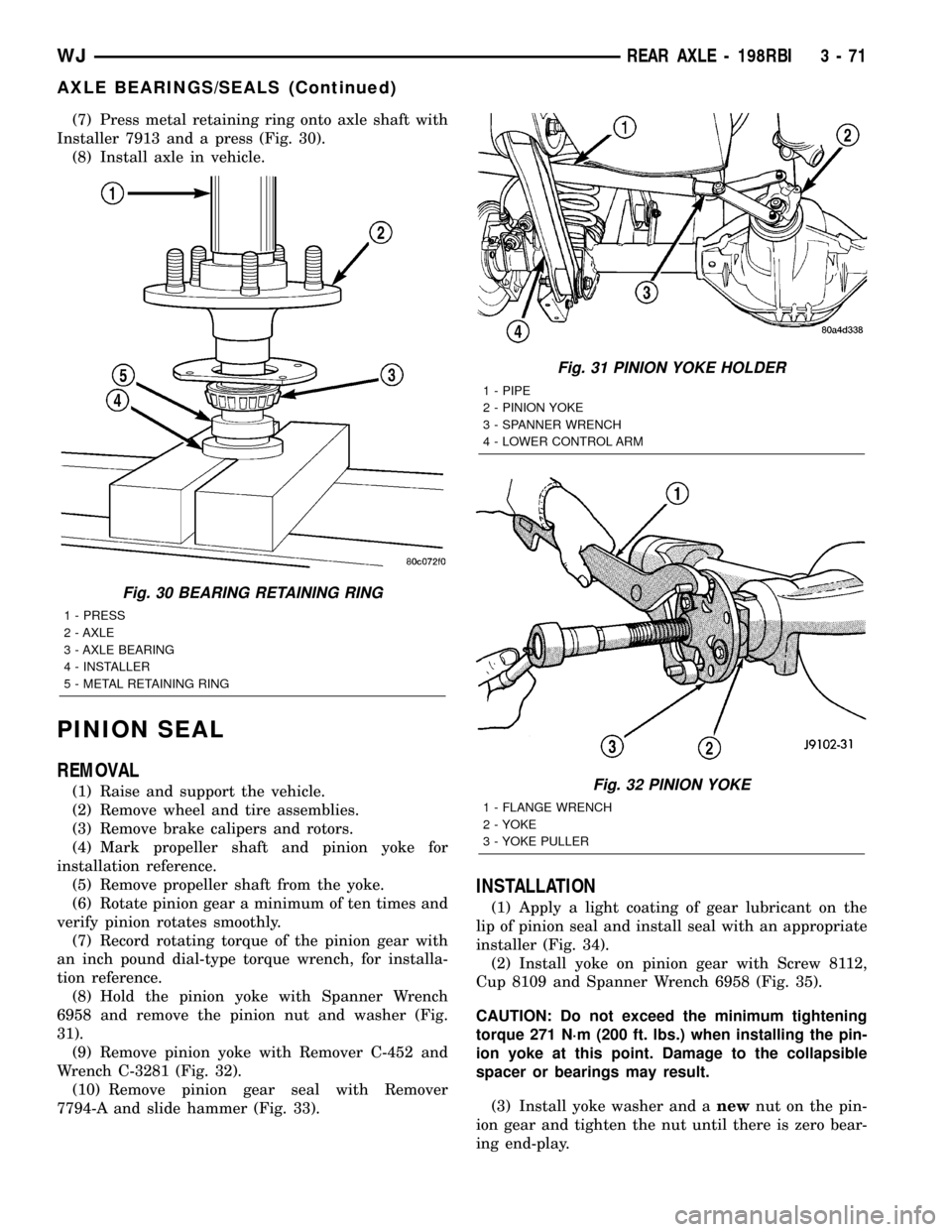
(7) Press metal retaining ring onto axle shaft with
Installer 7913 and a press (Fig. 30).
(8) Install axle in vehicle.
PINION SEAL
REMOVAL
(1) Raise and support the vehicle.
(2) Remove wheel and tire assemblies.
(3) Remove brake calipers and rotors.
(4) Mark propeller shaft and pinion yoke for
installation reference.
(5) Remove propeller shaft from the yoke.
(6) Rotate pinion gear a minimum of ten times and
verify pinion rotates smoothly.
(7) Record rotating torque of the pinion gear with
an inch pound dial-type torque wrench, for installa-
tion reference.
(8) Hold the pinion yoke with Spanner Wrench
6958 and remove the pinion nut and washer (Fig.
31).
(9) Remove pinion yoke with Remover C-452 and
Wrench C-3281 (Fig. 32).
(10) Remove pinion gear seal with Remover
7794-A and slide hammer (Fig. 33).
INSTALLATION
(1) Apply a light coating of gear lubricant on the
lip of pinion seal and install seal with an appropriate
installer (Fig. 34).
(2) Install yoke on pinion gear with Screw 8112,
Cup 8109 and Spanner Wrench 6958 (Fig. 35).
CAUTION: Do not exceed the minimum tightening
torque 271 N´m (200 ft. lbs.) when installing the pin-
ion yoke at this point. Damage to the collapsible
spacer or bearings may result.
(3) Install yoke washer and anewnut on the pin-
ion gear and tighten the nut until there is zero bear-
ing end-play.
Fig. 30 BEARING RETAINING RING
1 - PRESS
2 - AXLE
3 - AXLE BEARING
4 - INSTALLER
5 - METAL RETAINING RING
Fig. 31 PINION YOKE HOLDER
1 - PIPE
2 - PINION YOKE
3 - SPANNER WRENCH
4 - LOWER CONTROL ARM
Fig. 32 PINION YOKE
1 - FLANGE WRENCH
2 - YOKE
3 - YOKE PULLER
WJREAR AXLE - 198RBI 3 - 71
AXLE BEARINGS/SEALS (Continued)
Page 118 of 2199
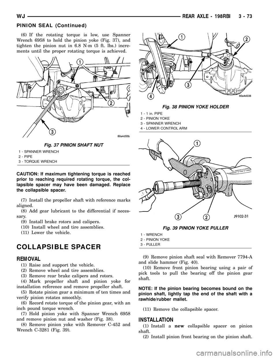
(6) If the rotating torque is low, use Spanner
Wrench 6958 to hold the pinion yoke (Fig. 37), and
tighten the pinion nut in 6.8 N´m (5 ft. lbs.) incre-
ments until the proper rotating torque is achieved.
CAUTION: If maximum tightening torque is reached
prior to reaching required rotating torque, the col-
lapsible spacer may have been damaged. Replace
the collapsible spacer.
(7) Install the propeller shaft with reference marks
aligned.
(8) Add gear lubricant to the differential if neces-
sary.
(9) Install brake rotors and calipers.
(10) Install wheel and tire assemblies.
(11) Lower the vehicle.
COLLAPSIBLE SPACER
REMOVAL
(1) Raise and support the vehicle.
(2) Remove wheel and tire assemblies.
(3) Remove rear brake calipers and rotors.
(4) Mark propeller shaft and pinion yoke for
installation reference and remove propeller shaft.
(5) Rotate pinion gear a minimum of ten times and
verify pinion rotates smoothly.
(6) Record rotate torque of the pinion gear, with an
inch pound torque wrench.
(7) Hold pinion yoke with Spanner Wrench 6958
and remove pinion nut and washer (Fig. 38).
(8) Remove pinion yoke with Remover C-452 and
Wrench C-3281 (Fig. 39).(9) Remove pinion shaft seal with Remover 7794-A
and slide hammer (Fig. 40).
(10) Remove front pinion bearing using a pair of
pick tools to pull the bearing off the pinion gear
shaft.
NOTE: If the pinion bearing becomes bound on the
pinion shaft, lightly tap the end of the shaft with a
rawhide/rubber mallet.
(11) Remove the collapsible spacer.
INSTALLATION
(1) Install anewcollapsible spacer on pinion
shaft.
(2) Install pinion front bearing on the pinion shaft.
Fig. 37 PINION SHAFT NUT
1 - SPANNER WRENCH
2 - PIPE
3 - TORQUE WRENCH
Fig. 38 PINION YOKE HOLDER
1 - 1 in. PIPE
2 - PINION YOKE
3 - SPANNER WRENCH
4 - LOWER CONTROL ARM
Fig. 39 PINION YOKE PULLER
1 - WRENCH
2 - PINION YOKE
3 - PULLER
WJREAR AXLE - 198RBI 3 - 73
PINION SEAL (Continued)
Page 129 of 2199
INSTALLATION
NOTE: If differential side bearings or differential
case are replaced, differential side bearing shim
requirements may change. Refer to Adjustments
(Differential Bearing Preload and Gear Backlash) for
procedures.
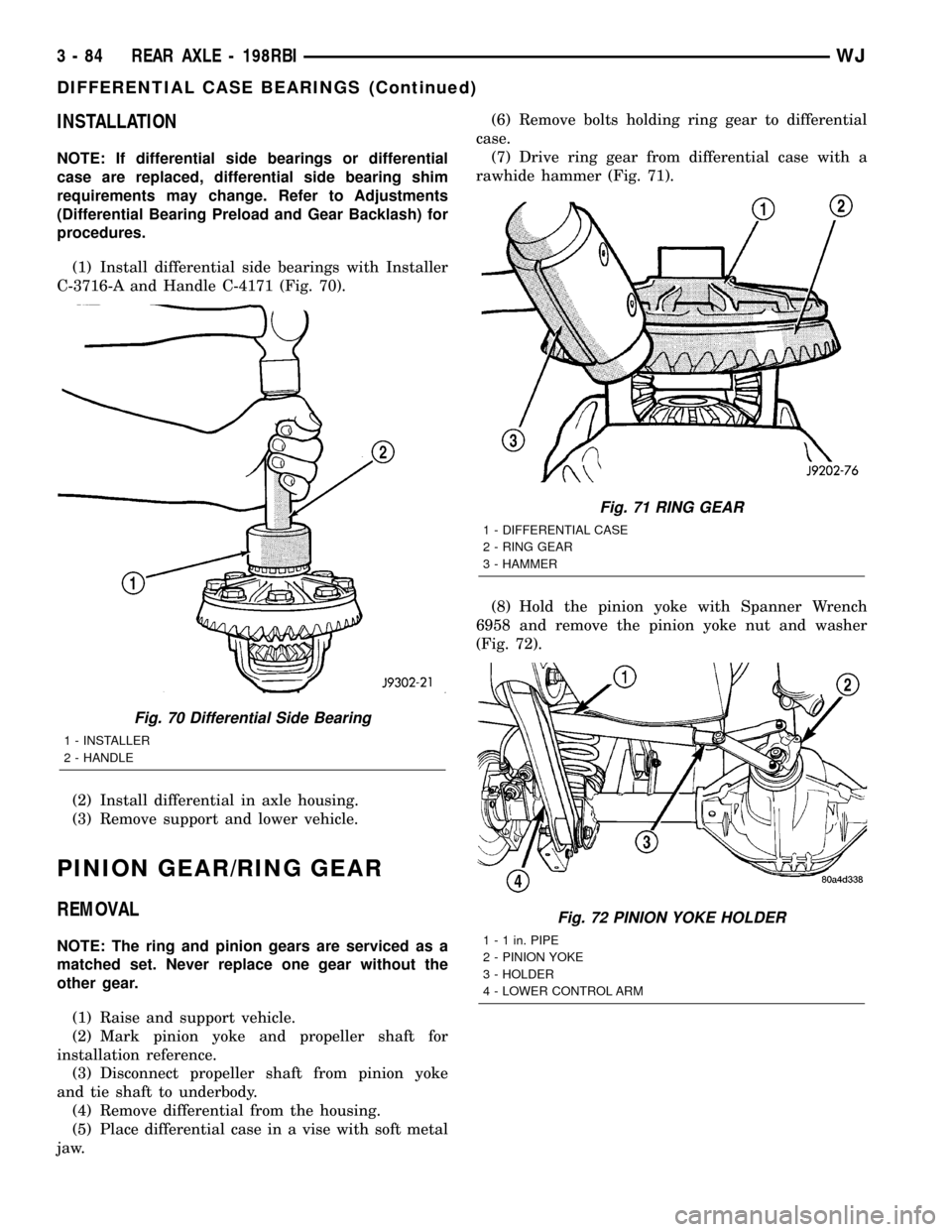
(1) Install differential side bearings with Installer
C-3716-A and Handle C-4171 (Fig. 70).
(2) Install differential in axle housing.
(3) Remove support and lower vehicle.
PINION GEAR/RING GEAR
REMOVAL
NOTE: The ring and pinion gears are serviced as a
matched set. Never replace one gear without the
other gear.
(1) Raise and support vehicle.
(2) Mark pinion yoke and propeller shaft for
installation reference.
(3) Disconnect propeller shaft from pinion yoke
and tie shaft to underbody.
(4) Remove differential from the housing.
(5) Place differential case in a vise with soft metal
jaw.(6) Remove bolts holding ring gear to differential
case.
(7) Drive ring gear from differential case with a
rawhide hammer (Fig. 71).
(8) Hold the pinion yoke with Spanner Wrench
6958 and remove the pinion yoke nut and washer
(Fig. 72).
Fig. 70 Differential Side Bearing
1 - INSTALLER
2 - HANDLE
Fig. 71 RING GEAR
1 - DIFFERENTIAL CASE
2 - RING GEAR
3 - HAMMER
Fig. 72 PINION YOKE HOLDER
1 - 1 in. PIPE
2 - PINION YOKE
3 - HOLDER
4 - LOWER CONTROL ARM
3 - 84 REAR AXLE - 198RBIWJ
DIFFERENTIAL CASE BEARINGS (Continued)
Page 137 of 2199
and therefore creates pressure in the pump. The tun-
ing of the front and rear axle orifices and valves
inside the gerotor pump is unique and each system
includes a torque-limiting pressure relief valve to
protect the clutch pack, which also facilitates vehicle
control under extreme side-to-side traction varia-
tions. The resulting pressure is applied to the clutch
pack and the transfer of torque is completed.
Under conditions in which opposite wheels are on
surfaces with widely different friction characteristics,
Vari-loktdelivers far more torque to the wheel on
the higher traction surface than do conventional
Trac-loktsystems. Because conventional Trac-lokt
differentials are initially pre-loaded to assure torque
transfer, normal driving (where inner and outer
wheel speeds differ during cornering, etc.) produces
torque transfer during even slight side-to-side speed
variations. Since these devices rely on friction from
this preload to transfer torque, normal use tends to
cause wear that reduces the ability of the differential
to transfer torque over time. By design, the Vari-lokt
system is less subject to wear, remaining more con-
sistent over time in its ability to transfer torque. The
coupling assembly is serviced as a unit. From a ser-
vice standpoint the coupling also benefits from using
the same lubricant supply as the ring and pinion
gears.
DIAGNOSIS AND TESTING
GEAR NOISE
Axle gear noise can be caused by insufficient lubri-
cant, incorrect backlash, tooth contact, worn/damaged
gears, or the carrier housing not having the proper
offset and squareness.
Gear noise usually happens at a specific speed
range. The noise can also occur during a specific type
of driving condition. These conditions are accelera-
tion, deceleration, coast, or constant load.
When road testing, first warm-up the axle fluid by
driving the vehicle at least 5 miles and then acceler-
ate the vehicle to the speed range where the noise is
the greatest. Shift out-of-gear and coast through the
peak-noise range. If the noise stops or changes
greatly:
²Check for insufficient lubricant.
²Incorrect ring gear backlash.
²Gear damage.
Differential side gears and pinions can be checked
by turning the vehicle. They usually do not cause
noise during straight-ahead driving when the gears
are unloaded. The side gears are loaded during vehi-
cle turns. A worn pinion mate shaft can also cause a
snapping or a knocking noise.
BEARING NOISE
The axle shaft, differential and pinion bearings can
all produce noise when worn or damaged. Bearing
noise can be either a whining, or a growling sound.
Pinion bearings have a constant-pitch noise. This
noise changes only with vehicle speed. Pinion bearing
noise will be higher pitched because it rotates at a
faster rate. Drive the vehicle and load the differen-
tial. If bearing noise occurs, the rear pinion bearing
is the source of the noise. If the bearing noise is
heard during a coast, the front pinion bearing is the
source.
Worn or damaged differential bearings usually pro-
duce a low pitch noise. Differential bearing noise is
similar to pinion bearing noise. The pitch of differen-
tial bearing noise is also constant and varies only
with vehicle speed.
Axle shaft bearings produce noise and vibration
when worn or damaged. The noise generally changes
when the bearings are loaded. Road test the vehicle.
Turn the vehicle sharply to the left and to the right.
This will load the bearings and change the noise
level. Where axle bearing damage is slight, the noise
is usually not noticeable at speeds above 30 mph.
LOW SPEED KNOCK
Low speed knock is generally caused by a worn
U-joint or by worn side±gear thrust washers. A worn
pinion shaft bore will also cause low speed knock.
VIBRATION
Vibration at the rear of the vehicle is usually
caused by a:
²Damaged drive shaft.
²Missing drive shaft balance weight(s).
²Worn or out-of-balance wheels.
²Loose wheel lug nuts.
²Worn U-joint(s).
²Loose/broken springs.
²Damaged axle shaft bearing(s).
²Loose pinion gear nut.
²Excessive pinion yoke run out.
²Bent axle shaft(s).
Check for loose or damaged front-end components
or engine/transmission mounts. These components
can contribute to what appears to be a rearend vibra-
tion. Do not overlook engine accessories, brackets
and drive belts.
All driveline components should be examined
before starting any repair.
(Refer to 22 - TIRES/WHEELS - DIAGNOSIS AND
TESTING)
3 - 92 REAR AXLE - 226RBAWJ
REAR AXLE - 226RBA (Continued)
Page 156 of 2199
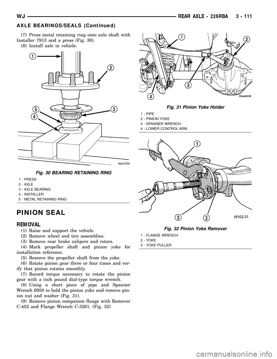
(7) Press metal retaining ring onto axle shaft with
Installer 7913 and a press (Fig. 30).
(8) Install axle in vehicle.
PINION SEAL
REMOVAL
(1) Raise and support the vehicle.
(2) Remove wheel and tire assemblies.
(3) Remove rear brake calipers and rotors.
(4) Mark propeller shaft and pinion yoke for
installation reference.
(5) Remove the propeller shaft from the yoke.
(6) Rotate pinion gear three or four times and ver-
ify that pinion rotates smoothly.
(7) Record torque necessary to rotate the pinion
gear with a inch pound dial-type torque wrench.
(8) Using a short piece of pipe and Spanner
Wrench 6958 to hold the pinion yoke and remove pin-
ion nut and washer (Fig. 31).
(9) Remove pinion companion flange with Remover
C-452 and Flange Wrench C-3281. (Fig. 32)
Fig. 30 BEARING RETAINING RING
1 - PRESS
2 - AXLE
3 - AXLE BEARING
4 - INSTALLER
5 - METAL RETAINING RING
Fig. 31 Pinion Yoke Holder
1 - PIPE
2 - PINION YOKE
3 - SPANNER WRENCH
4 - LOWER CONTROL ARM
Fig. 32 Pinion Yoke Remover
1 - FLANGE WRENCH
2 - YOKE
3 - YOKE PULLER
WJREAR AXLE - 226RBA 3 - 111
AXLE BEARINGS/SEALS (Continued)
Page 158 of 2199
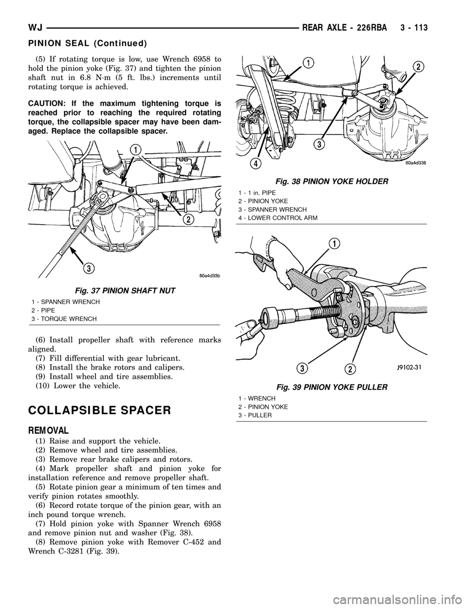
(5) If rotating torque is low, use Wrench 6958 to
hold the pinion yoke (Fig. 37) and tighten the pinion
shaft nut in 6.8 N´m (5 ft. lbs.) increments until
rotating torque is achieved.
CAUTION: If the maximum tightening torque is
reached prior to reaching the required rotating
torque, the collapsible spacer may have been dam-
aged. Replace the collapsible spacer.
(6) Install propeller shaft with reference marks
aligned.
(7) Fill differential with gear lubricant.
(8) Install the brake rotors and calipers.
(9) Install wheel and tire assemblies.
(10) Lower the vehicle.
COLLAPSIBLE SPACER
REMOVAL
(1) Raise and support the vehicle.
(2) Remove wheel and tire assemblies.
(3) Remove rear brake calipers and rotors.
(4) Mark propeller shaft and pinion yoke for
installation reference and remove propeller shaft.
(5) Rotate pinion gear a minimum of ten times and
verify pinion rotates smoothly.
(6) Record rotate torque of the pinion gear, with an
inch pound torque wrench.
(7) Hold pinion yoke with Spanner Wrench 6958
and remove pinion nut and washer (Fig. 38).
(8) Remove pinion yoke with Remover C-452 and
Wrench C-3281 (Fig. 39).
Fig. 37 PINION SHAFT NUT
1 - SPANNER WRENCH
2 - PIPE
3 - TORQUE WRENCH
Fig. 38 PINION YOKE HOLDER
1 - 1 in. PIPE
2 - PINION YOKE
3 - SPANNER WRENCH
4 - LOWER CONTROL ARM
Fig. 39 PINION YOKE PULLER
1 - WRENCH
2 - PINION YOKE
3 - PULLER
WJREAR AXLE - 226RBA 3 - 113
PINION SEAL (Continued)
Page 169 of 2199
CAUTION: Vari-lokTplenum must be seated against
the differential case prior to installing the ring gear
side differential bearing.
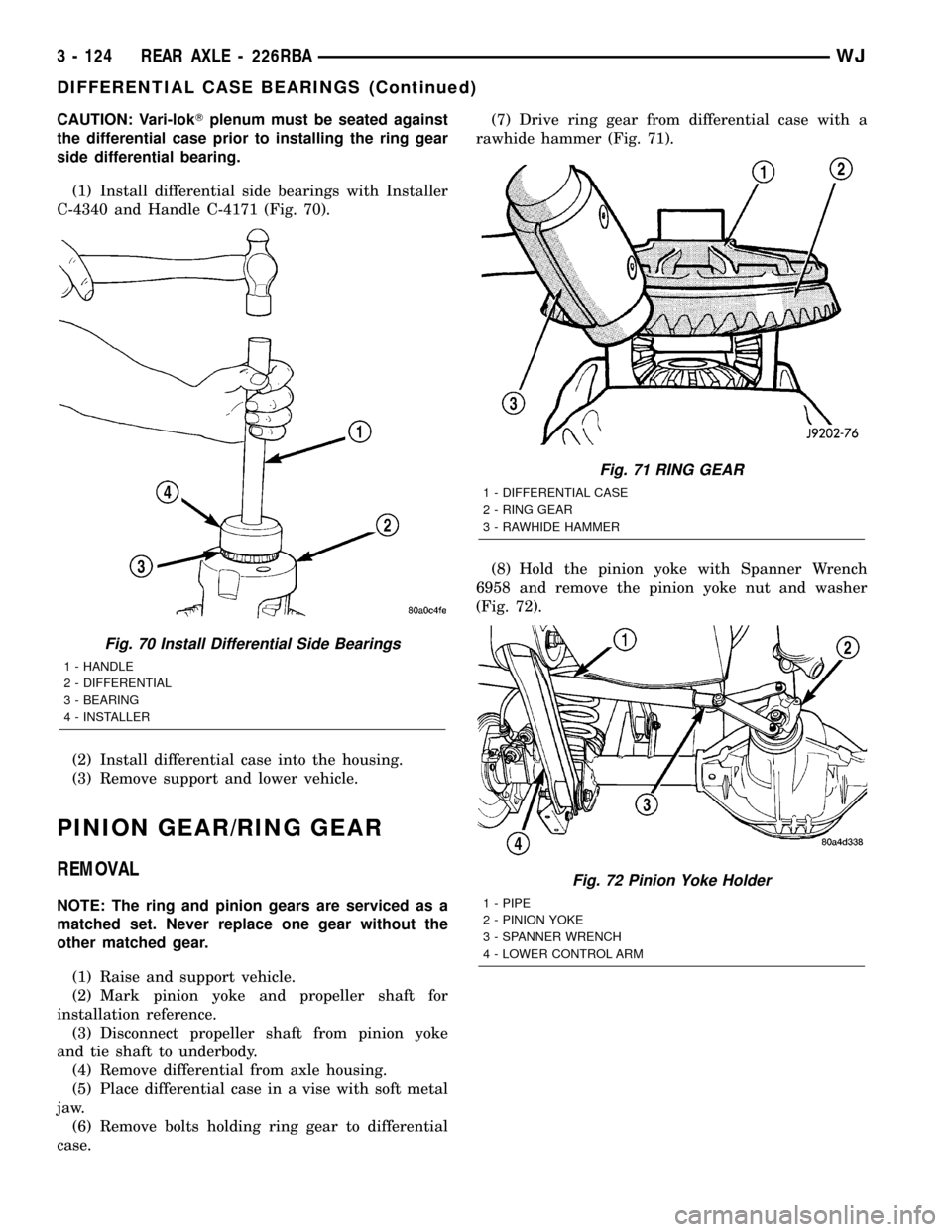
(1) Install differential side bearings with Installer
C-4340 and Handle C-4171 (Fig. 70).
(2) Install differential case into the housing.
(3) Remove support and lower vehicle.
PINION GEAR/RING GEAR
REMOVAL
NOTE: The ring and pinion gears are serviced as a
matched set. Never replace one gear without the
other matched gear.
(1) Raise and support vehicle.
(2) Mark pinion yoke and propeller shaft for
installation reference.
(3) Disconnect propeller shaft from pinion yoke
and tie shaft to underbody.
(4) Remove differential from axle housing.
(5) Place differential case in a vise with soft metal
jaw.
(6) Remove bolts holding ring gear to differential
case.(7) Drive ring gear from differential case with a
rawhide hammer (Fig. 71).
(8) Hold the pinion yoke with Spanner Wrench
6958 and remove the pinion yoke nut and washer
(Fig. 72).
Fig. 70 Install Differential Side Bearings
1 - HANDLE
2 - DIFFERENTIAL
3 - BEARING
4 - INSTALLER
Fig. 71 RING GEAR
1 - DIFFERENTIAL CASE
2 - RING GEAR
3 - RAWHIDE HAMMER
Fig. 72 Pinion Yoke Holder
1 - PIPE
2 - PINION YOKE
3 - SPANNER WRENCH
4 - LOWER CONTROL ARM
3 - 124 REAR AXLE - 226RBAWJ
DIFFERENTIAL CASE BEARINGS (Continued)
Page 229 of 2199
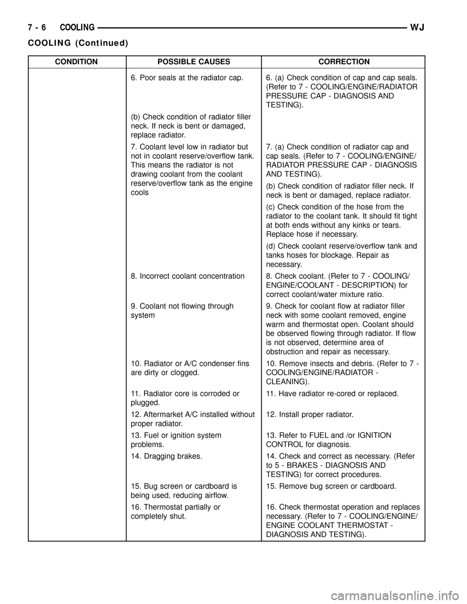
CONDITION POSSIBLE CAUSES CORRECTION
6. Poor seals at the radiator cap. 6. (a) Check condition of cap and cap seals.
(Refer to 7 - COOLING/ENGINE/RADIATOR
PRESSURE CAP - DIAGNOSIS AND
TESTING).
(b) Check condition of radiator filler
neck. If neck is bent or damaged,
replace radiator.
7. Coolant level low in radiator but
not in coolant reserve/overflow tank.
This means the radiator is not
drawing coolant from the coolant
reserve/overflow tank as the engine
cools7. (a) Check condition of radiator cap and
cap seals. (Refer to 7 - COOLING/ENGINE/
RADIATOR PRESSURE CAP - DIAGNOSIS
AND TESTING).
(b) Check condition of radiator filler neck. If
neck is bent or damaged, replace radiator.
(c) Check condition of the hose from the
radiator to the coolant tank. It should fit tight
at both ends without any kinks or tears.
Replace hose if necessary.
(d) Check coolant reserve/overflow tank and
tanks hoses for blockage. Repair as
necessary.
8. Incorrect coolant concentration 8. Check coolant. (Refer to 7 - COOLING/
ENGINE/COOLANT - DESCRIPTION) for
correct coolant/water mixture ratio.
9. Coolant not flowing through
system9. Check for coolant flow at radiator filler
neck with some coolant removed, engine
warm and thermostat open. Coolant should
be observed flowing through radiator. If flow
is not observed, determine area of
obstruction and repair as necessary.
10. Radiator or A/C condenser fins
are dirty or clogged.10. Remove insects and debris. (Refer to 7 -
COOLING/ENGINE/RADIATOR -
CLEANING).
11. Radiator core is corroded or
plugged.11. Have radiator re-cored or replaced.
12. Aftermarket A/C installed without
proper radiator.12. Install proper radiator.
13. Fuel or ignition system
problems.13. Refer to FUEL and /or IGNITION
CONTROL for diagnosis.
14. Dragging brakes. 14. Check and correct as necessary. (Refer
to 5 - BRAKES - DIAGNOSIS AND
TESTING) for correct procedures.
15. Bug screen or cardboard is
being used, reducing airflow.15. Remove bug screen or cardboard.
16. Thermostat partially or
completely shut.16. Check thermostat operation and replaces
necessary. (Refer to 7 - COOLING/ENGINE/
ENGINE COOLANT THERMOSTAT -
DIAGNOSIS AND TESTING).
7 - 6 COOLINGWJ
COOLING (Continued)
Page 232 of 2199
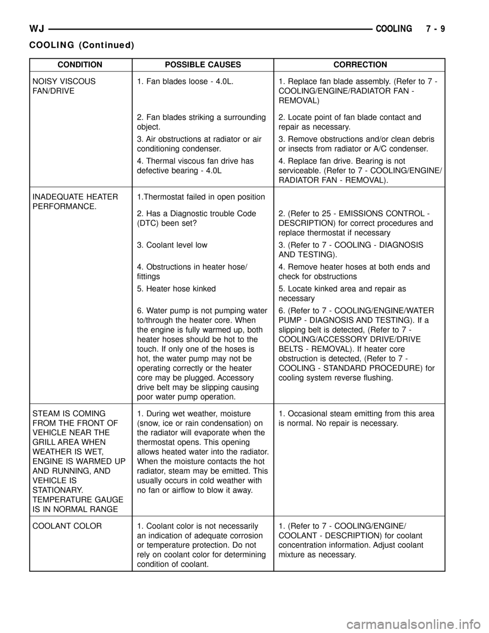
CONDITION POSSIBLE CAUSES CORRECTION
NOISY VISCOUS
FAN/DRIVE1. Fan blades loose - 4.0L. 1. Replace fan blade assembly. (Refer to 7 -
COOLING/ENGINE/RADIATOR FAN -
REMOVAL)
2. Fan blades striking a surrounding
object.2. Locate point of fan blade contact and
repair as necessary.
3. Air obstructions at radiator or air
conditioning condenser.3. Remove obstructions and/or clean debris
or insects from radiator or A/C condenser.
4. Thermal viscous fan drive has
defective bearing - 4.0L4. Replace fan drive. Bearing is not
serviceable. (Refer to 7 - COOLING/ENGINE/
RADIATOR FAN - REMOVAL).
INADEQUATE HEATER
PERFORMANCE.1.Thermostat failed in open position
2. Has a Diagnostic trouble Code
(DTC) been set?2. (Refer to 25 - EMISSIONS CONTROL -
DESCRIPTION) for correct procedures and
replace thermostat if necessary
3. Coolant level low 3. (Refer to 7 - COOLING - DIAGNOSIS
AND TESTING).
4. Obstructions in heater hose/
fittings4. Remove heater hoses at both ends and
check for obstructions
5. Heater hose kinked 5. Locate kinked area and repair as
necessary
6. Water pump is not pumping water
to/through the heater core. When
the engine is fully warmed up, both
heater hoses should be hot to the
touch. If only one of the hoses is
hot, the water pump may not be
operating correctly or the heater
core may be plugged. Accessory
drive belt may be slipping causing
poor water pump operation.6. (Refer to 7 - COOLING/ENGINE/WATER
PUMP - DIAGNOSIS AND TESTING). If a
slipping belt is detected, (Refer to 7 -
COOLING/ACCESSORY DRIVE/DRIVE
BELTS - REMOVAL). If heater core
obstruction is detected, (Refer to 7 -
COOLING - STANDARD PROCEDURE) for
cooling system reverse flushing.
STEAM IS COMING
FROM THE FRONT OF
VEHICLE NEAR THE
GRILL AREA WHEN
WEATHER IS WET,
ENGINE IS WARMED UP
AND RUNNING, AND
VEHICLE IS
STATIONARY.
TEMPERATURE GAUGE
IS IN NORMAL RANGE1. During wet weather, moisture
(snow, ice or rain condensation) on
the radiator will evaporate when the
thermostat opens. This opening
allows heated water into the radiator.
When the moisture contacts the hot
radiator, steam may be emitted. This
usually occurs in cold weather with
no fan or airflow to blow it away.1. Occasional steam emitting from this area
is normal. No repair is necessary.
COOLANT COLOR 1. Coolant color is not necessarily
an indication of adequate corrosion
or temperature protection. Do not
rely on coolant color for determining
condition of coolant.1. (Refer to 7 - COOLING/ENGINE/
COOLANT - DESCRIPTION) for coolant
concentration information. Adjust coolant
mixture as necessary.
WJCOOLING 7 - 9
COOLING (Continued)
Page 233 of 2199
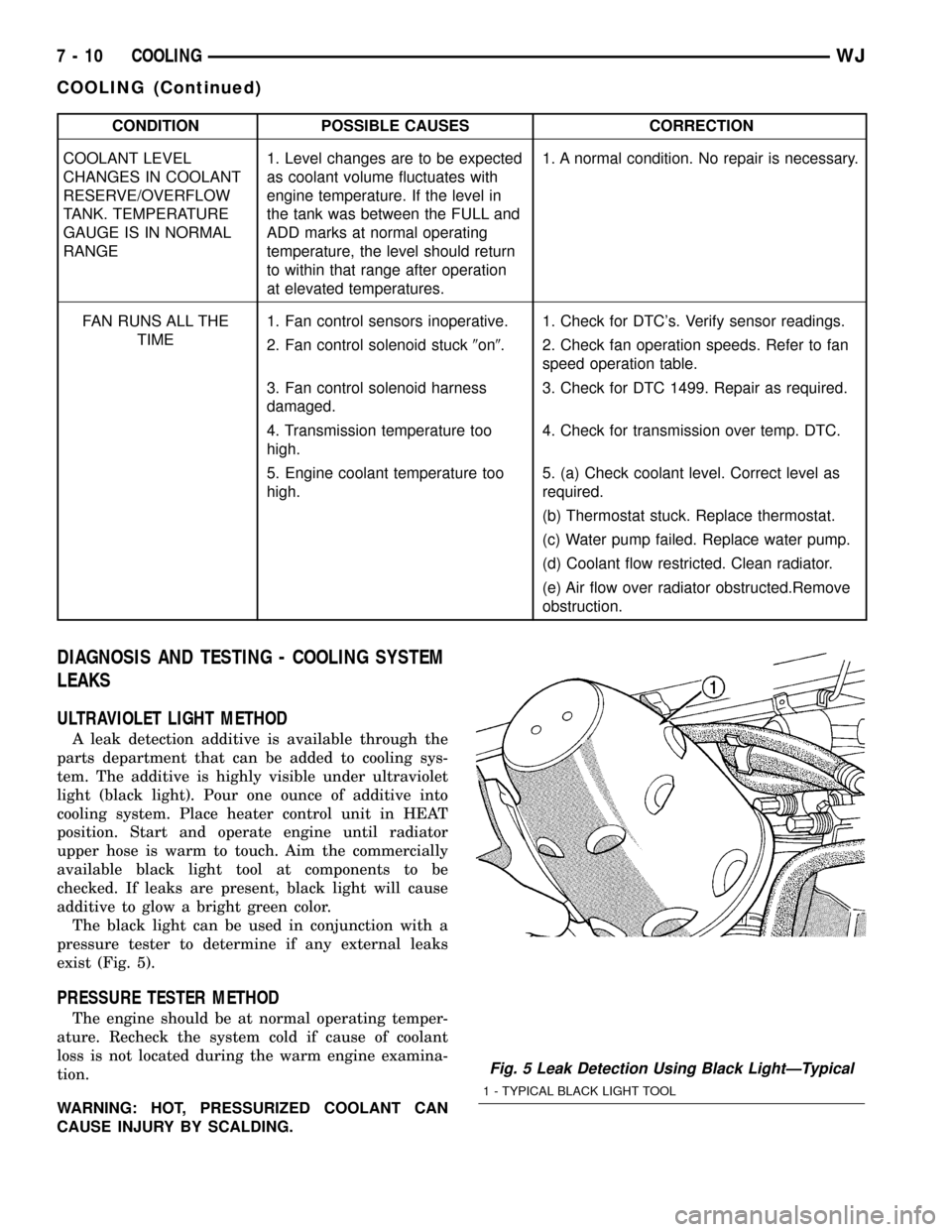
CONDITION POSSIBLE CAUSES CORRECTION
COOLANT LEVEL
CHANGES IN COOLANT
RESERVE/OVERFLOW
TANK. TEMPERATURE
GAUGE IS IN NORMAL
RANGE1. Level changes are to be expected
as coolant volume fluctuates with
engine temperature. If the level in
the tank was between the FULL and
ADD marks at normal operating
temperature, the level should return
to within that range after operation
at elevated temperatures.1. A normal condition. No repair is necessary.
FAN RUNS ALL THE
TIME1. Fan control sensors inoperative. 1. Check for DTC's. Verify sensor readings.
2. Fan control solenoid stuck9on9. 2. Check fan operation speeds. Refer to fan
speed operation table.
3. Fan control solenoid harness
damaged.3. Check for DTC 1499. Repair as required.
4. Transmission temperature too
high.4. Check for transmission over temp. DTC.
5. Engine coolant temperature too
high.5. (a) Check coolant level. Correct level as
required.
(b) Thermostat stuck. Replace thermostat.
(c) Water pump failed. Replace water pump.
(d) Coolant flow restricted. Clean radiator.
(e) Air flow over radiator obstructed.Remove
obstruction.
DIAGNOSIS AND TESTING - COOLING SYSTEM
LEAKS
ULTRAVIOLET LIGHT METHOD
A leak detection additive is available through the
parts department that can be added to cooling sys-
tem. The additive is highly visible under ultraviolet
light (black light). Pour one ounce of additive into
cooling system. Place heater control unit in HEAT
position. Start and operate engine until radiator
upper hose is warm to touch. Aim the commercially
available black light tool at components to be
checked. If leaks are present, black light will cause
additive to glow a bright green color.
The black light can be used in conjunction with a
pressure tester to determine if any external leaks
exist (Fig. 5).
PRESSURE TESTER METHOD
The engine should be at normal operating temper-
ature. Recheck the system cold if cause of coolant
loss is not located during the warm engine examina-
tion.
WARNING: HOT, PRESSURIZED COOLANT CAN
CAUSE INJURY BY SCALDING.
Fig. 5 Leak Detection Using Black LightÐTypical
1 - TYPICAL BLACK LIGHT TOOL
7 - 10 COOLINGWJ
COOLING (Continued)