Weld JEEP GRAND CHEROKEE 2002 WJ / 2.G User Guide
[x] Cancel search | Manufacturer: JEEP, Model Year: 2002, Model line: GRAND CHEROKEE, Model: JEEP GRAND CHEROKEE 2002 WJ / 2.GPages: 2199, PDF Size: 76.01 MB
Page 1398 of 2199
EXHAUST SYSTEM
TABLE OF CONTENTS
page page
EXHAUST SYSTEM
DESCRIPTION - EXHAUST SYSTEM.........1
DIAGNOSIS AND TESTING - EXHAUST
SYSTEM.............................3
SPECIFICATIONS
TORQUE.............................3
CATALYTIC CONVERTER - 4.0L
DESCRIPTION - CATALYTIC CONVERTER
4.0L ENGINE..........................4
REMOVAL.............................4
INSPECTION...........................5
INSTALLATION..........................5
CATALYTIC CONVERTER - 4.7L
DESCRIPTION - CATALYTIC CONVERTER.....6
REMOVAL.............................6
INSPECTION...........................7
INSTALLATION..........................7EXHAUST PIPE - 4.0L
REMOVAL.............................8
INSPECTION...........................8
INSTALLATION..........................8
EXHAUST PIPE - 4.7L
REMOVAL.............................10
INSPECTION..........................10
INSTALLATION.........................10
HEAT SHIELDS
DESCRIPTION.........................12
MUFFLER
DESCRIPTION.........................12
REMOVAL.............................12
INSTALLATION.........................12
TAILPIPE
DESCRIPTION.........................13
OPERATION...........................13
EXHAUST SYSTEM
DESCRIPTION - EXHAUST SYSTEM
WARNING: THE NORMAL OPERATING TEMPERA-
TURE OF THE EXHAUST SYSTEM IS VERY HIGH.
THEREFORE, NEVER WORK AROUND OR ATTEMPT
TO SERVICE ANY PART OF THE EXHAUST SYSTEM
UNTIL IT IS COOLED. SPECIAL CARE SHOULD BE
TAKEN WHEN WORKING NEAR THE CATALYTIC
CONVERTER. THE TEMPERATURE OF THE CON-
VERTER RISES TO A HIGH LEVEL AFTER A SHORT
PERIOD OF ENGINE OPERATION TIME.
CAUTION: Avoid application of rust prevention com-
pounds or undercoating materials to exhaust sys-
tem floor pan heat shields. Light overspray near the
edges is permitted. Application of coating will result
in excessive floor pan temperatures and objection-
able fumes.
The exhaust system uses a single muffler with a
welded tailpipe.The 50 State Emissions vehicles use two mini cat-
alytic converters inline with the exhaust pipe below
the exhaust manifolds.
The exhaust manifolds are equipped with ball
flange outlets to assure a tight seal and strain free
connections.
The exhaust system must be properly aligned to
prevent stress, leakage and body contact. If the sys-
tem contacts any body panel, it may amplify objec-
tionable noises originating from the engine or body.
When inspecting an exhaust system, critically
inspect for cracked or loose joints, stripped screw or
bolt threads, corrosion damage and worn, cracked or
broken hangers. Replace all components that are
badly corroded or damaged. DO NOT attempt to
repair.
When replacement is required, use original equip-
ment parts (or their equivalent). This will assure
proper alignment and provide acceptable exhaust
noise levels.
The basic exhaust system consists of exhaust man-
ifold(s), exhaust pipe with oxygen sensors, catalytic
converter(s), heat shield(s), muffler and tailpipe (Fig.
1) and (Fig. 2).
WJEXHAUST SYSTEM 11 - 1
Page 1409 of 2199

HEAT SHIELDS
DESCRIPTION
Heat shields are needed to protect both the vehicle
and the environment from the high temperatures
developed by the catalytic converter. The catalytic
converter releases additional heat into the exhaust
system. Under severe operating conditions, the tem-
perature increases in the area of the converter. Such
conditions can exist when the engine misfires or oth-
erwise does not operate at peak efficiency (Fig. 17).
MUFFLER
DESCRIPTION
Both the 4.0L and 4.7L engines use a stainless
steel muffler to control exhaust noise levels and
exhaust back pressure. The muffler and tailpipe are
a one piece assembly (Fig. 18).
REMOVAL
All original equipment exhaust systems are manu-
factured with the tailpipe welded to the muffler. Ser-
vice replacement mufflers and tailpipes are either
clamped together or welded together.
WARNING: IF TORCHES ARE USED WHEN WORK-
ING ON THE EXHAUST SYSTEM, DO NOT ALLOW
THE FLAME NEAR THE FUEL LINES.
(1) Raise and support the vehicle.
(2) Saturate the bolts and nuts with heat valve
lubricant. Allow 5 minutes for penetration.(3) Loosen the exhaust clamp on the catalytic con-
verter to muffler connection (Fig. 19).
(4) Heat the catalytic converter-to-muffler connec-
tion with a torch until the metal becomes cherry red.
(5) While the metal is still cherry red, remove the
tailpipe/muffler assembly from the catalytic con-
verter.
(6) Remove the tailpipe from the tailpipe hanger
(Fig. 20).
(7) Remove the tailpipe/muffler assembly (Fig. 20).
INSTALLATION
(1) If the tailpipe hanger assembly was removed,
install the hanger to the frame. Tighten the bolts to
22 N´m (192 in. lbs.) torque.
(2) Position the tailpipe and muffler onto the
tailpipe hanger (Fig. 20) .
(3) Install the muffler onto the catalytic converter.
Make sure that the tailpipe has sufficient clearance
from the floor pan. Install exhaust clamp and tighten
the nuts to 47 N´m (35 ft. lbs.) torque (Fig. 19) .
(4) Lower the vehicle.
(5) Start the engine and inspect for exhaust leaks
and exhaust system contact with the body panels.
Adjust the alignment, if needed.
Fig. 17 Front and Rear Floor Pan Heat Shields
Typical
1 - REAR FLOOR PAN HEAT SHIELD
2 - HEAT SHIELD RETAINING NUTS (QTY 8)
3 - FRONT FLOOR PAN HEAT SHIELD
Fig. 18 Muffler and Tailpipe
1 - CATALYTIC CONVERTER
2 - TAILPIPE HANGER
3 - TAILPIPE
4 - MUFFLER
11 - 12 EXHAUST SYSTEMWJ
Page 1535 of 2199
leaks are generally deposited on the housing and not
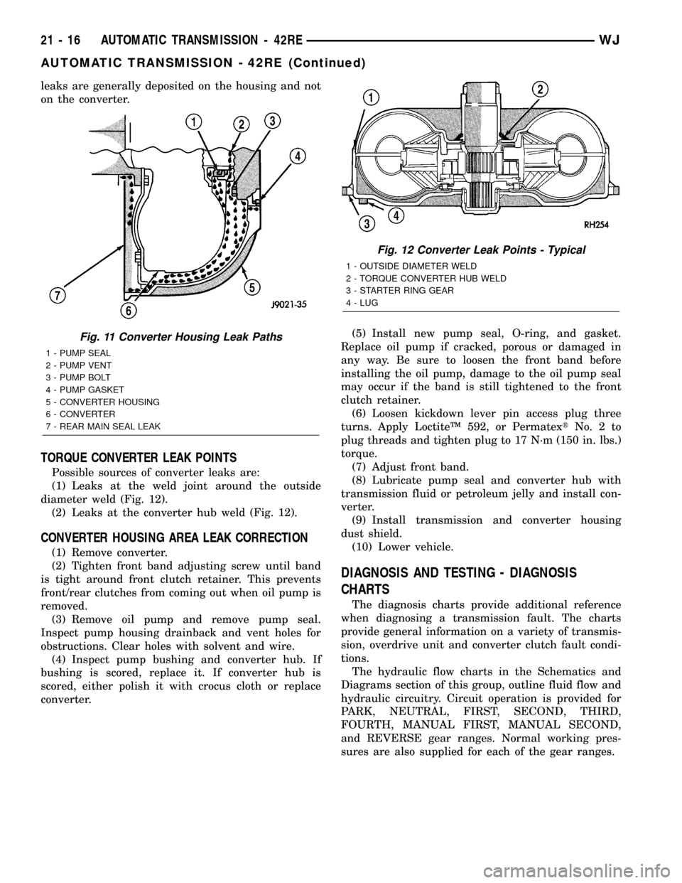
on the converter.
TORQUE CONVERTER LEAK POINTS
Possible sources of converter leaks are:
(1) Leaks at the weld joint around the outside
diameter weld (Fig. 12).
(2) Leaks at the converter hub weld (Fig. 12).
CONVERTER HOUSING AREA LEAK CORRECTION
(1) Remove converter.
(2) Tighten front band adjusting screw until band
is tight around front clutch retainer. This prevents
front/rear clutches from coming out when oil pump is
removed.
(3) Remove oil pump and remove pump seal.
Inspect pump housing drainback and vent holes for
obstructions. Clear holes with solvent and wire.
(4) Inspect pump bushing and converter hub. If
bushing is scored, replace it. If converter hub is
scored, either polish it with crocus cloth or replace
converter.(5) Install new pump seal, O-ring, and gasket.
Replace oil pump if cracked, porous or damaged in
any way. Be sure to loosen the front band before
installing the oil pump, damage to the oil pump seal
may occur if the band is still tightened to the front
clutch retainer.
(6) Loosen kickdown lever pin access plug three
turns. Apply LoctiteŸ 592, or PermatextNo.2to
plug threads and tighten plug to 17 N´m (150 in. lbs.)
torque.
(7) Adjust front band.
(8) Lubricate pump seal and converter hub with
transmission fluid or petroleum jelly and install con-
verter.
(9) Install transmission and converter housing
dust shield.
(10) Lower vehicle.
DIAGNOSIS AND TESTING - DIAGNOSIS
CHARTS
The diagnosis charts provide additional reference
when diagnosing a transmission fault. The charts
provide general information on a variety of transmis-
sion, overdrive unit and converter clutch fault condi-
tions.
The hydraulic flow charts in the Schematics and
Diagrams section of this group, outline fluid flow and
hydraulic circuitry. Circuit operation is provided for
PARK, NEUTRAL, FIRST, SECOND, THIRD,
FOURTH, MANUAL FIRST, MANUAL SECOND,
and REVERSE gear ranges. Normal working pres-
sures are also supplied for each of the gear ranges.
Fig. 11 Converter Housing Leak Paths
1 - PUMP SEAL
2 - PUMP VENT
3 - PUMP BOLT
4 - PUMP GASKET
5 - CONVERTER HOUSING
6 - CONVERTER
7 - REAR MAIN SEAL LEAK
Fig. 12 Converter Leak Points - Typical
1 - OUTSIDE DIAMETER WELD
2 - TORQUE CONVERTER HUB WELD
3 - STARTER RING GEAR
4 - LUG
21 - 16 AUTOMATIC TRANSMISSION - 42REWJ
AUTOMATIC TRANSMISSION - 42RE (Continued)
Page 1545 of 2199
CONDITION POSSIBLE CAUSES CORRECTION
OIL LEAKS. 1. Fluid Lines and Fittings
Loose/Leaks/Damaged.1. Tighten fittings. If leaks persist, replace fittings
and lines if necessary.
2. Fill Tube (where tube enters
case) Leaks/Damaged.2. Replace tube seal. Inspect tube for cracks in fill
tube.
3. Pressure Port Plug Loose
Loose/Damaged.3. Tighten to correct torque. Replace plug or
reseal if leak persists.
4. Pan Gasket Leaks. 4. Tighten pan screws (150 in. lbs.). If leaks
persist, replace gasket.
5. Valve Body Manual Lever Shaft
Seal Leaks/Worn.5. Replace shaft seal.
6. Rear Bearing Access Plate
Leaks.6. Replace gasket. Tighten screws.
7. Gasket Damaged or Bolts are
Loose.7. Replace bolts or gasket or tighten both.
8. Adapter/Extension Gasket
Damaged Leaks/Damaged.8. Replace gasket.
9. Park/Neutral Switch, or
Transmission Range Sensor
Leaks/Damaged.9. Replace switch and gasket.
10. Converter Housing Area Leaks. 10. Check for leaks at seal caused by worn seal
or burr on converter hub (cutting seal), worn
bushing, missing oil return, oil in front pump
housing or hole plugged. Check for leaks past
O-ring seal on pump or past pump-to-case bolts;
pump housing porous, oil coming out vent due to
overfill or leak past front band shaft access plug.
11. Pump Seal Leaks/Worn/
Damaged.11. Replace seal.
12. Torque Converter Weld
Leak/Cracked Hub.12. Replace converter.
13. Case Porosity Leaks. 13. Replace case.
NOISY OPERATION
IN FOURTH GEAR
ONLY1. Overdrive Clutch Discs, Plates
or Snap Rings Damaged.1. Remove unit and rebuild clutch pack.
2. Overdrive Piston or Planetary
Thrust Bearing Damaged.2. Remove and disassemble unit. Replace either
thrust bearing if damaged.
3. Output Shaft Bearings
Scored/Damaged.3. Remove and disassemble unit. Replace either
bearing if damaged.
4. Planetary Gears Worn/Chipped. 4. Remove and overhaul overdrive unit.
5. Overdrive Unit Overrunning
Clutch Rollers Worn/Scored.5. Remove and overhaul overdrive unit.
STANDARD PROCEDURE - ALUMINUM
THREAD REPAIR
Damaged or worn threads in the aluminum trans-
mission case and valve body can be repaired by the
use of Heli-CoilsŸ, or equivalent. This repair con-
sists of drilling out the worn-out damaged threads.
Then tap the hole with a special Heli-CoilŸ tap, or
equivalent, and installing a Heli-CoilŸ insert, orequivalent, into the hole. This brings the hole back to
its original thread size.
Heli-CoilŸ, or equivalent, tools and inserts are
readily available from most automotive parts suppli-
ers.
21 - 26 AUTOMATIC TRANSMISSION - 42REWJ
AUTOMATIC TRANSMISSION - 42RE (Continued)
Page 1647 of 2199

NOTE: Be sure that as the cable is pulled forward
and centered on the throttle lever stud, the cable
housing moves smoothly with the cable. Due to the
angle at which the cable housing enters the spring
housing, the cable housing may bind slightly and
create an incorrect adjustment.
(8) Reconnect the T.V. cable (B) to the throttle
bellcrank lever (C).
(9) Check cable adjustment. Verify transmission
throttle lever and lever on throttle body move simul-
taneously.
TORQUE CONVERTER
DESCRIPTION
The torque converter (Fig. 245) is a hydraulic
device that couples the engine crankshaft to the
transmission. The torque converter consists of an
outer shell with an internal turbine, a stator, an
overrunning clutch, an impeller and an electronically
applied converter clutch. The converter clutch pro-
vides reduced engine speed and greater fuel economy
when engaged. Clutch engagement also provides
reduced transmission fluid temperatures. The torque
converter hub drives the transmission oil (fluid)
pump.
The torque converter is a sealed, welded unit that
is not repairable and is serviced as an assembly.
CAUTION: The torque converter must be replaced if
a transmission failure resulted in large amounts of
metal or fiber contamination in the fluid. If the fluid
is contaminated, flush the all transmission fluid
cooler(s) and lines.
Fig. 244 Throttle Valve Cable at Throttle Linkage
1 - THROTTLE LINKAGE
2 - THROTTLE VALVE CABLE LOCKING CLIP
3 - THROTTLE VALVE CABLE
Fig. 245 Torque Converter Assembly
1 - TURBINE
2 - IMPELLER
3 - HUB
4-STATOR
5 - FRONT COVER
6 - CONVERTER CLUTCH DISC
7 - DRIVE PLATE
21 - 128 AUTOMATIC TRANSMISSION - 42REWJ
THROTTLE VALVE CABLE (Continued)
Page 1702 of 2199
TORQUE CONVERTER LEAK POINTS
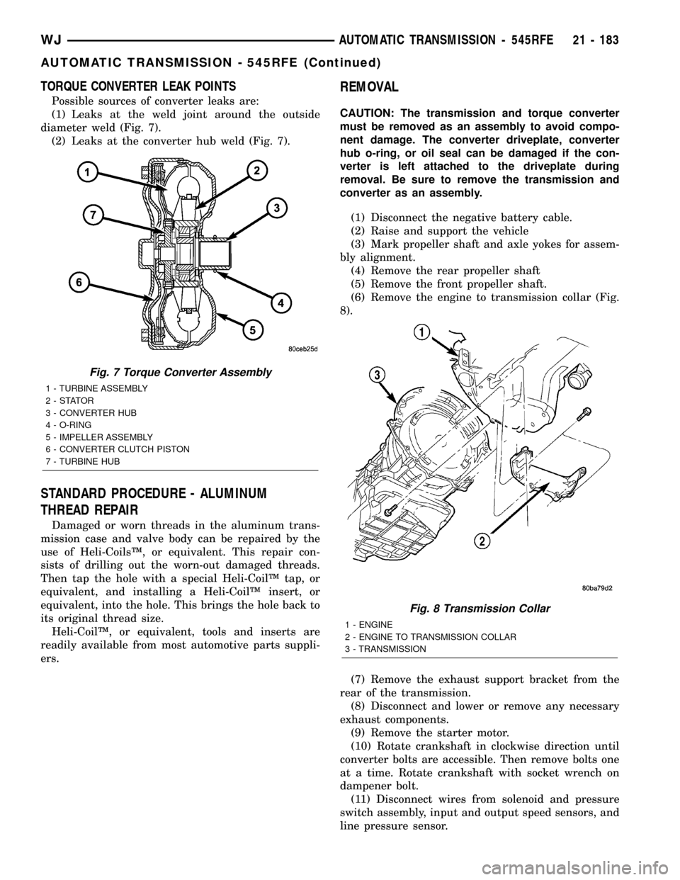
Possible sources of converter leaks are:
(1) Leaks at the weld joint around the outside
diameter weld (Fig. 7).
(2) Leaks at the converter hub weld (Fig. 7).
STANDARD PROCEDURE - ALUMINUM
THREAD REPAIR
Damaged or worn threads in the aluminum trans-
mission case and valve body can be repaired by the
use of Heli-CoilsŸ, or equivalent. This repair con-
sists of drilling out the worn-out damaged threads.
Then tap the hole with a special Heli-CoilŸ tap, or
equivalent, and installing a Heli-CoilŸ insert, or
equivalent, into the hole. This brings the hole back to
its original thread size.
Heli-CoilŸ, or equivalent, tools and inserts are
readily available from most automotive parts suppli-
ers.
REMOVAL
CAUTION: The transmission and torque converter
must be removed as an assembly to avoid compo-
nent damage. The converter driveplate, converter
hub o-ring, or oil seal can be damaged if the con-
verter is left attached to the driveplate during
removal. Be sure to remove the transmission and
converter as an assembly.
(1) Disconnect the negative battery cable.
(2) Raise and support the vehicle
(3) Mark propeller shaft and axle yokes for assem-
bly alignment.
(4) Remove the rear propeller shaft
(5) Remove the front propeller shaft.
(6) Remove the engine to transmission collar (Fig.
8).
(7) Remove the exhaust support bracket from the
rear of the transmission.
(8) Disconnect and lower or remove any necessary
exhaust components.
(9) Remove the starter motor.
(10) Rotate crankshaft in clockwise direction until
converter bolts are accessible. Then remove bolts one
at a time. Rotate crankshaft with socket wrench on
dampener bolt.
(11) Disconnect wires from solenoid and pressure
switch assembly, input and output speed sensors, and
line pressure sensor.
Fig. 7 Torque Converter Assembly
1 - TURBINE ASSEMBLY
2-STATOR
3 - CONVERTER HUB
4 - O-RING
5 - IMPELLER ASSEMBLY
6 - CONVERTER CLUTCH PISTON
7 - TURBINE HUB
Fig. 8 Transmission Collar
1 - ENGINE
2 - ENGINE TO TRANSMISSION COLLAR
3 - TRANSMISSION
WJAUTOMATIC TRANSMISSION - 545RFE 21 - 183
AUTOMATIC TRANSMISSION - 545RFE (Continued)
Page 1783 of 2199

A solenoid can also be described by the method by
which it is controlled. Some of the possibilities
include variable force, pulse-width modulated, con-
stant ON, or duty cycle. The variable force and pulse-
width modulated versions utilize similar methods to
control the current flow through the solenoid to posi-
tion the solenoid plunger at a desired position some-
where between full ON and full OFF. The constant
ON and duty cycled versions control the voltage
across the solenoid to allow either full flow or no flow
through the solenoid's valve.
OPERATION
When an electrical current is applied to the sole-
noid coil, a magnetic field is created which produces
an attraction to the plunger, causing the plunger to
move and work against the spring pressure and the
load applied by the fluid the valve is controlling. The
plunger is normally directly attached to the valve
which it is to operate. When the current is removed
from the coil, the attraction is removed and the
plunger will return to its original position due to
spring pressure.
The plunger is made of a conductive material and
accomplishes this movement by providing a path for
the magnetic field to flow. By keeping the air gap
between the plunger and the coil to the minimum
necessary to allow free movement of the plunger, the
magnetic field is maximized.
TORQUE CONVERTER
DESCRIPTION
The torque converter (Fig. 109) is a hydraulic
device that couples the engine crankshaft to the
transmission. The torque converter consists of an
outer shell with an internal turbine, a stator, an
overrunning clutch, an impeller and an electronically
applied converter clutch. The converter clutch pro-vides reduced engine speed and greater fuel economy
when engaged. Clutch engagement also provides
reduced transmission fluid temperatures. The con-
verter clutch engages in third gear. The torque con-
verter hub drives the transmission oil (fluid) pump
and contains an o-ring seal to better control oil flow.
The torque converter is a sealed, welded unit that
is not repairable and is serviced as an assembly.
CAUTION: The torque converter must be replaced if
a transmission failure resulted in large amounts of
metal or fiber contamination in the fluid. If the fluid
is contaminated, flush the fluid cooler and lines.
Fig. 109 Torque Converter Assembly
1 - TURBINE ASSEMBLY
2-STATOR
3 - CONVERTER HUB
4 - O-RING
5 - IMPELLER ASSEMBLY
6 - CONVERTER CLUTCH PISTON
7 - TURBINE HUB
21 - 264 AUTOMATIC TRANSMISSION - 545RFEWJ
SOLENOIDS (Continued)
Page 1869 of 2199

SPARE TIRE
DESCRIPTION - SPARE / TEMPORARY TIRE
The temporary spare tire is designed for emer-
gency use only. The original tire should be repaired
or replaced at the first opportunity, then reinstalled.
Do not exceed speeds of 50 M.P.H. when using the
temporary spare tire. Refer to Owner's Manual for
complete details.
WHEELS
DESCRIPTION
The rim size is on the vehicle safety certification
label located on the drivers door shut face. The size
of the rim is determined by the drivetrain package.
Original equipment wheels/rims are designed for
operation up to the specified maximum vehicle capac-
ity.
All models use stamped steel, cast aluminum or
forged aluminum wheels. Every wheel has raised sec-
tions between the rim flanges and rim drop well
called safety humps (Fig. 18) .
Initial inflation of the tire forces the bead over
these raised sections. In case of rapid loss of air pres-
sure, the raised sections help hold the tire on the
wheel.
The wheel studs and nuts are designed for specific
applications. All aluminum and some steel wheels
have wheel stud nuts with an enlarged nose. This
enlarged nose is necessary to ensure proper retentionof the wheels. Do not use replacement studs or nuts
with a different design or lesser quality.
DIAGNOSIS AND TESTING - WHEEL
INSPECTION
Inspect wheels for:
²Excessive run out
²Dents or cracks
²Damaged wheel lug nut holes
²Air Leaks from any area or surface of the rim
NOTE: Do not attempt to repair a wheel by hammer-
ing, heating or welding.
If a wheel is damaged an original equipment
replacement wheel should be used. When obtaining
replacement wheels, they should be equivalent in
load carrying capacity. The diameter, width, offset,
pilot hole and bolt circle of the wheel should be the
same as the original wheel.
WARNING: FAILURE TO USE EQUIVALENT
REPLACEMENT WHEELS MAY ADVERSELY
AFFECT THE SAFETY AND HANDLING OF THE
VEHICLE. USED WHEELS ARE NOT RECOM-
MENDED. THE SERVICE HISTORY OF THE WHEEL
MAY HAVE INCLUDED SEVERE TREATMENT OR
VERY HIGH MILEAGE. THE RIM COULD FAIL WITH-
OUT WARNING.
STANDARD PROCEDURE - WHEEL
REPLACEMENT
The wheel studs and nuts are designed for specific
applications. They must be replaced with equivalent
parts. Do not use replacement parts of lesser quality
or a substitute design. All aluminum and some steel
wheels have wheel stud nuts which feature an
enlarged nose. This enlarged nose is necessary to
ensure proper retention of the aluminum wheels.
NOTE: Do not use chrome plated lug nuts with
chrome plated wheels.
Before installing the wheel, be sure to remove any
build up of corrosion on the wheel mounting surfaces.
Ensure wheels are installed with good metal-to-metal
contact. Improper installation could cause loosening
of wheel nuts. This could affect the safety and han-
dling of your vehicle.
To install the wheel, first position it properly on
the mounting surface. All wheel nuts should then be
tightened just snug. Gradually tighten them in
sequence to the proper torque specification.Never
use oil or grease on studs or nuts.
Wheels must be replaced if they have:
²Excessive runout
Fig. 18 Safety Rim
1 - FLANGE
2 - RIDGE
3 - WELL
22 - 10 TIRES/WHEELSWJ
Page 1870 of 2199
²Bent or dented
²Leak air through welds
²Have damaged bolt holes
Wheel repairs employing hammering, heating, or
welding are not allowed.
Original equipment wheels are available through
your dealer. Replacement wheels from any other
source should be equivalent in:
²Load carrying capacity
²Diameter
²Width²Offset
²Mounting configuration
Failure to use equivalent replacement wheels may
affect the safety and handling of your vehicle.
Replacement withusedwheels is not recommended.
Their service history may have included severe treat-
ment.
SPECIFICATIONS
TORQUE CHART
TORQUE SPECIFICATIONS
DESCRIPTION N´m Ft. Lbs. In. Lbs.
Lug Nut
1/2 X 20 with 60É Cone115-150 85-115 Ð
STUDS
REMOVAL
CAUTION: Do not use a hammer to remove wheel
studs.
(1) Raise and support vehicle.
(2) Remove wheel and tire assembly.
(3) Remove brake caliper, caliper adapter and
rotor,(Refer to 5 - BRAKES/HYDRAULIC/MECHAN-
ICAL/ROTORS - REMOVAL).
(4) Remove stud from hub with Remover C-4150A
(Fig. 19).
INSTALLATION
CAUTION: Do not use a hammer to remove wheel
studs.
(1) Install the new stud into the hub flange.
(2) Install the three washers onto the stud, then
install the lug nut with the flat side of the nut
against the washers.
(3) Tighten the lug nut until the stud is pulled
into the hub flange. Verify that the stud is properly
seated into the flange.
(4) Remove the lug nut and washers.
(5) Install the brake rotor, caliper adapter, and
caliper,(Refer to 5 - BRAKES/HYDRAULIC/ME-
CHANICAL/DISC BRAKE CALIPERS - INSTALLA-
TION).(6) Install the wheel and tire assembly, use new
lug nut on stud or studs that were replaced.
(7) Remove the support and lower vehicle.Fig. 19 Wheel Stud Removal
1 - REMOVER
2 - WHEEL STUD
WJTIRES/WHEELS 22 - 11
WHEELS (Continued)
Page 1874 of 2199
BODY
TABLE OF CONTENTS
page page
BODY
DIAGNOSIS AND TESTING
WATER LEAKS........................1
WIND NOISE..........................2
STANDARD PROCEDURE
STANDARD PROCEDURE - BODY
LUBRICATION.........................2
STANDARD PROCEDURE - DRILLING AND
WELDING............................3
SPECIFICATIONS
BODY LUBRICANTS....................3
SPECIFICATIONS - TORQUE.............4
SPECIAL TOOLS
BODY...............................4DECKLID/HATCH/LIFTGATE/TAILGATE........5
DOOR - FRONT.........................11
DOORS - REAR.........................19
EXTERIOR.............................25
HOOD.................................33
INSTRUMENT PANEL SYSTEM.............36
INTERIOR..............................69
PAINT.................................81
SEATS................................83
STATIONARY GLASS.....................93
SUNROOF.............................96
WEATHERSTRIP/SEALS..................105
BODY STRUCTURE.....................112
BODY
DIAGNOSIS AND TESTING
WATER LEAKS
Water leaks can be caused by poor sealing,
improper body component alignment, body seam
porosity, missing plugs, or blocked drain holes. Cen-
trifugal and gravitational force can cause water to
drip from a location away from the actual leak point,
making leak detection difficult. All body sealing
points should be water tight in normal wet-driving
conditions. Water flowing downward from the front of
the vehicle should not enter the passenger or luggage
compartment. Moving sealing surfaces will not
always seal water tight under all conditions. At
times, side glass or door seals will allow water to
enter the passenger compartment during high pres-
sure washing or hard driving rain (severe) condi-
tions. Overcompensating on door or glass
adjustments to stop a water leak that occurs under
severe conditions can cause premature seal wear and
excessive closing or latching effort. After completing
a repair, water test vehicle to verify leak has stopped
before returning vehicle to use.
VISUAL INSPECTION BEFORE WATER LEAK TESTS
Verify that floor and body plugs are in place, body
drains are clear, and body components are properly
aligned and sealed. If component alignment or seal-
ing is necessary, refer to the appropriate section of
this group for proper procedures.
WATER LEAK TESTS
WARNING: DO NOT USE ELECTRIC SHOP LIGHTS
OR TOOLS IN WATER TEST AREA. PERSONAL
INJURY CAN RESULT.
When the conditions causing a water leak have
been determined, simulate the conditions as closely
as possible.
²If a leak occurs with the vehicle parked in a
steady light rain, flood the leak area with an open-
ended garden hose.
²If a leak occurs while driving at highway speeds
in a steady rain, test the leak area with a reasonable
velocity stream or fan spray of water. Direct the
spray in a direction comparable to actual conditions.
²If a leak occurs when the vehicle is parked on an
incline, hoist the end or side of the vehicle to simu-
late this condition. This method can be used when
the leak occurs when the vehicle accelerates, stops or
turns. If the leak occurs on acceleration, hoist the
front of the vehicle. If the leak occurs when braking,
hoist the back of the vehicle. If the leak occurs on left
turns, hoist the left side of the vehicle. If the leak
occurs on right turns, hoist the right side of the vehi-
cle. For hoisting recommendations refer to Group 0,
Lubrication and Maintenance, General Information
section.
WATER LEAK DETECTION
To detect a water leak point-of-entry, do a water
test and watch for water tracks or droplets forming
on the inside of the vehicle. If necessary, remove inte-
rior trim covers or panels to gain visual access to the
WJBODY 23 - 1