Weld JEEP GRAND CHEROKEE 2002 WJ / 2.G Workshop Manual
[x] Cancel search | Manufacturer: JEEP, Model Year: 2002, Model line: GRAND CHEROKEE, Model: JEEP GRAND CHEROKEE 2002 WJ / 2.GPages: 2199, PDF Size: 76.01 MB
Page 47 of 2199
DRIVELINE VIBRATION
Drive Condition Possible Cause Correction
Propeller Shaft Noise 1) Undercoating or other foreign material
on shaft.1) Clean exterior of shaft and wash with
solvent.
2) Loose U-joint clamp screws. 2) Install new clamps and screws and
tighten to proper torque.
3) Loose or bent U-joint yoke or
excessive runout.3) Install new yoke.
4) Incorrect driveline angularity. 4) Measure and correct driveline angles.
5) Rear spring center bolt not in seat. 5) Loosen spring u-bolts and seat center
bolt.
6) Worn U-joint bearings. 6) Install new U-joint.
7) Propeller shaft damaged or out of
balance.7) Installl new propeller shaft.
8) Broken rear spring. 8) Install new rear spring.
9) Excessive runout or unbalanced
condition.9) Re-index propeller shaft, test, and
evaluate.
10) Excessive drive pinion gear shaft
runout.10) Re-index propeller shaft and evaluate.
11) Excessive axle yoke deflection. 11) Inspect and replace yoke if necessary.
12) Excessive transfer case runout. 12) Inspect and repair as necessary.
Universal Joint Noise 1) Loose U-joint clamp screws. 1) Install new clamps and screws and
tighten to proper torque.
2) Lack of lubrication. 2) Replace U-joints as necessary.
BALANCE
NOTE: Removing and re-indexing the propeller
shaft 180É relative to the yoke may eliminate some
vibrations.
If propeller shaft is suspected of being unbalanced,
it can be verified with the following procedure:
(1) Raise the vehicle.
(2) Clean all the foreign material from the propel-
ler shaft and the universal joints.
(3) Inspect the propeller shaft for missing balance
weights, broken welds, and bent areas.If the pro-
peller shaft is bent, it must be replaced.
(4) Inspect the universal joints to ensure that they
are not worn, are properly installed, and are cor-
rectly aligned with the shaft.
(5) Check the universal joint clamp screws torque.
(6) Remove the wheels and tires. Install the wheel
lug nuts to retain the brake drums or rotors.
(7) Mark and number the shaft six inches from the
yoke end at four positions 90É apart.
(8) Run and accelerate the vehicle until vibration
occurs. Note the intensity and speed the vibration
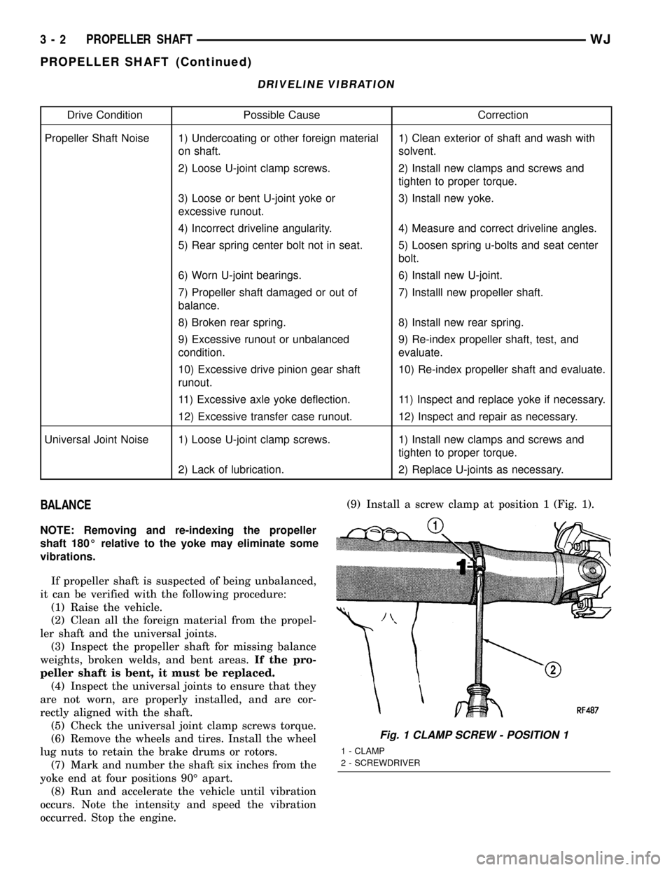
occurred. Stop the engine.(9) Install a screw clamp at position 1 (Fig. 1).
Fig. 1 CLAMP SCREW - POSITION 1
1 - CLAMP
2 - SCREWDRIVER
3 - 2 PROPELLER SHAFTWJ
PROPELLER SHAFT (Continued)
Page 48 of 2199
(10) Start the engine and re-check for vibration. If
there is little or no change in vibration, move the
clamp to one of the other three positions. Repeat the
vibration test.
(11) If there is no difference in vibration at the
other positions, the source of the vibration may not
be propeller shaft.
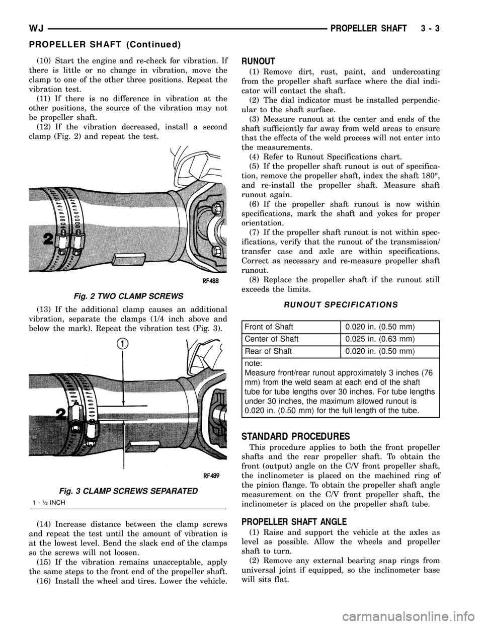
(12) If the vibration decreased, install a second
clamp (Fig. 2) and repeat the test.
(13) If the additional clamp causes an additional
vibration, separate the clamps (1/4 inch above and
below the mark). Repeat the vibration test (Fig. 3).
(14) Increase distance between the clamp screws
and repeat the test until the amount of vibration is
at the lowest level. Bend the slack end of the clamps
so the screws will not loosen.
(15) If the vibration remains unacceptable, apply
the same steps to the front end of the propeller shaft.
(16) Install the wheel and tires. Lower the vehicle.RUNOUT
(1) Remove dirt, rust, paint, and undercoating
from the propeller shaft surface where the dial indi-
cator will contact the shaft.
(2) The dial indicator must be installed perpendic-
ular to the shaft surface.
(3) Measure runout at the center and ends of the
shaft sufficiently far away from weld areas to ensure
that the effects of the weld process will not enter into
the measurements.
(4) Refer to Runout Specifications chart.
(5) If the propeller shaft runout is out of specifica-
tion, remove the propeller shaft, index the shaft 180É,
and re-install the propeller shaft. Measure shaft
runout again.
(6) If the propeller shaft runout is now within
specifications, mark the shaft and yokes for proper
orientation.
(7) If the propeller shaft runout is not within spec-
ifications, verify that the runout of the transmission/
transfer case and axle are within specifications.
Correct as necessary and re-measure propeller shaft
runout.
(8) Replace the propeller shaft if the runout still
exceeds the limits.
RUNOUT SPECIFICATIONS
Front of Shaft 0.020 in. (0.50 mm)
Center of Shaft 0.025 in. (0.63 mm)
Rear of Shaft 0.020 in. (0.50 mm)
note:
Measure front/rear runout approximately 3 inches (76
mm) from the weld seam at each end of the shaft
tube for tube lengths over 30 inches. For tube lengths
under 30 inches, the maximum allowed runout is
0.020 in. (0.50 mm) for the full length of the tube.
STANDARD PROCEDURES
This procedure applies to both the front propeller
shafts and the rear propeller shaft. To obtain the
front (output) angle on the C/V front propeller shaft,
the inclinometer is placed on the machined ring of
the pinion flange. To obtain the propeller shaft angle
measurement on the C/V front propeller shaft, the
inclinometer is placed on the propeller shaft tube.
PROPELLER SHAFT ANGLE
(1) Raise and support the vehicle at the axles as
level as possible. Allow the wheels and propeller
shaft to turn.
(2) Remove any external bearing snap rings from
universal joint if equipped, so the inclinometer base
will sits flat.
Fig. 2 TWO CLAMP SCREWS
Fig. 3 CLAMP SCREWS SEPARATED
1 - ó INCH
WJPROPELLER SHAFT 3 - 3
PROPELLER SHAFT (Continued)
Page 60 of 2199
FRONT AXLE - 186FBI
TABLE OF CONTENTS
page page
FRONT AXLE - 186FBI
DESCRIPTION.........................15
OPERATION...........................15
DIAGNOSIS AND TESTING................16
REMOVAL.............................20
INSTALLATION.........................21
ADJUSTMENTS........................21
SPECIFICATIONS.......................30
SPECIAL TOOLS.......................31
AXLE SHAFTS
REMOVAL.............................34
INSTALLATION.........................34
AXLE SHAFT SEALS
REMOVAL.............................35
INSTALLATION.........................35
AXLE - C/V JOINT
REMOVAL.............................35
INSTALLATION.........................35
AXLE - U-JOINT
REMOVAL.............................36INSTALLATION.........................37
PINION SEAL
REMOVAL.............................37
INSTALLATION.........................37
COLLAPSIBLE SPACER
REMOVAL.............................39
INSTALLATION.........................39
DIFFERENTIAL
REMOVAL.............................40
DISASSEMBLY.........................42
ASSEMBLY............................42
INSTALLATION.........................43
DIFFERENTIAL CASE BEARINGS
REMOVAL.............................44
INSTALLATION.........................44
PINION GEAR/RING GEAR
REMOVAL.............................45
INSTALLATION.........................46
FRONT AXLE - 186FBI
DESCRIPTION
The Front Beam-design Iron (FBI) axle consists of
a cast iron differential housing with axle shaft tubes
extending from either side. The tubes are pressed
into the differential housing and welded. The axles
are semi-floating axle shafts, meaning the loads are
supported by the hub bearings. The axle shafts are
retained by nuts at the hub bearings.
The differential case is a one-piece design. Differ-
ential bearing preload and ring gear backlash is
adjusted by the use of shims located between the dif-
ferential bearing cups and housing. Pinion bearing
preload is set and maintained by the use of a collaps-
ible spacer. A differential cover provides a means for
inspection and servicing.
An optional Vari-Loktdifferential has a one-piece
differential case which contains the gerotor pump
assembly and the clutch mechinism. This unit is ser-
viced as an assembly.
OPERATION
The axle receives power from the transfer case
through the front propeller shaft. The front propeller
shaft is connected to the pinion gear which rotatesthe differential through the gear mesh with the ring
gear bolted to the differential case. The engine power
is transmitted to the axle shafts through the pinion
mate and side gears. The side gears are splined to
the axle shafts.
STANDARD DIFFERENTIAL
During straight-ahead driving, the differential pinion
gears do not rotate on the pinion mate shaft. This
occurs because input torque applied to the gears is
divided and distributed equally between the two side
gears. As a result, the pinion gears revolve with the pin-
ion mate shaft but do not rotate around it (Fig. 1).
When turning corners, the outside wheel must
travel a greater distance than the inside wheel to
complete a turn. The difference must be compensated
for to prevent the tires from scuffing and skidding
through turns. To accomplish this, the differential
allows the axle shafts to turn at unequal speeds (Fig.
2). In this instance, the input torque applied to the
pinion gears is not divided equally. The pinion gears
now rotate around the pinion mate shaft in opposite
directions. This allows the side gear and axle shaft
attached to the outside wheel to rotate at a faster
speed.
WJFRONT AXLE - 186FBI 3 - 15
Page 95 of 2199
REAR AXLE - 198RBI
TABLE OF CONTENTS
page page
REAR AXLE - 198RBI
DESCRIPTION.........................50
OPERATION...........................50
DIAGNOSIS AND TESTING................51
REMOVAL.............................55
INSTALLATION.........................56
ADJUSTMENTS........................56
SPECIFICATIONS.......................65
SPECIAL TOOLS.......................66
AXLE SHAFTS
REMOVAL.............................69
INSTALLATION.........................69
AXLE BEARINGS/SEALS
REMOVAL.............................69
INSTALLATION.........................70
PINION SEAL
REMOVAL.............................71
INSTALLATION.........................71
COLLAPSIBLE SPACER
REMOVAL.............................73INSTALLATION.........................73
DIFFERENTIAL
REMOVAL.............................75
DISASSEMBLY.........................77
ASSEMBLY............................77
INSTALLATION.........................77
DIFFERENTIAL-TRAC-LOC
DIAGNOSIS AND TESTING................79
DISASSEMBLY.........................79
CLEANING............................82
INSPECTION..........................82
ASSEMBLY............................82
DIFFERENTIAL CASE BEARINGS
REMOVAL.............................83
INSTALLATION.........................84
PINION GEAR/RING GEAR
REMOVAL.............................84
INSTALLATION.........................86
REAR AXLE - 198RBI
DESCRIPTION
The Rear Beam-design Iron (RBI) axle housing has
an iron center casting with axle shaft tubes extend-
ing from either side. The tubes are pressed into and
welded to the differential housing to form a one-piece
axle housing. The axles has semi-floating axle shafts,
meaning that loads are supported by the axle shaft
and bearings. The axle shafts are retained by bearing
retainer plates on the axles which are bolted to
flanges at the outboard end of the axle tubes.
The differential case is a one-piece design. Differ-
ential bearing preload and ring gear backlash is
adjusted by the use of selective spacer shims. Pinion
bearing preload is set and maintained by the use of a
collapsible spacer. A differential cover provides a
means for inspection and service.
Axles with optional Trac-Loktdifferential have a
one-piece differential case, and the same internal
components as a standard differential, plus two
clutch disc packs.
OPERATION
The axle receives power from the transmission/
transfer case through the rear propeller shaft. Therear propeller shaft is connected to the pinion gear
which rotates the differential through the gear mesh
with the ring gear bolted to the differential case. The
engine power is transmitted to the axle shafts
through the pinion mate and side gears. The side
gears are splined to the axle shafts.
STANDARD DIFFERENTIAL
During straight-ahead driving, the differential pin-
ion gears do not rotate on the pinion mate shaft. This
occurs because input torque applied to the gears is
divided and distributed equally between the two side
gears. As a result, the pinion gears revolve with the
pinion mate shaft but do not rotate around it (Fig. 1).
When turning corners, the outside wheel must
travel a greater distance than the inside wheel to
complete a turn. The difference must be compensated
for to prevent the tires from scuffing and skidding
through turns. To accomplish this, the differential
allows the axle shafts to turn at unequal speeds (Fig.
2). In this instance, the input torque applied to the
pinion gears is not divided equally. The pinion gears
now rotate around the pinion mate shaft in opposite
directions. This allows the side gear and axle shaft
attached to the outside wheel to rotate at a faster
speed.
3 - 50 REAR AXLE - 198RBIWJ
Page 255 of 2199
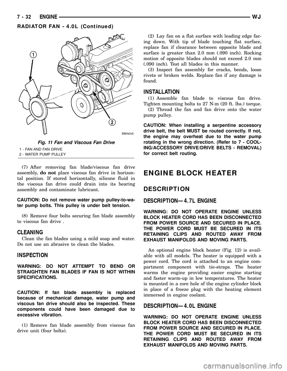
(7) After removing fan blade/viscous fan drive
assembly,do notplace viscous fan drive in horizon-
tal position. If stored horizontally, silicone fluid in
the viscous fan drive could drain into its bearing
assembly and contaminate lubricant.
CAUTION: Do not remove water pump pulley-to-wa-
ter pump bolts. This pulley is under belt tension.
(8) Remove four bolts securing fan blade assembly
to viscous fan drive .
CLEANING
Clean the fan blades using a mild soap and water.
Do not use an abrasive to clean the blades.
INSPECTION
WARNING: DO NOT ATTEMPT TO BEND OR
STRAIGHTEN FAN BLADES IF FAN IS NOT WITHIN
SPECIFICATIONS.
CAUTION: If fan blade assembly is replaced
because of mechanical damage, water pump and
viscous fan drive should also be inspected. These
components could have been damaged due to
excessive vibration.
(1) Remove fan blade assembly from viscous fan
drive unit (four bolts).(2) Lay fan on a flat surface with leading edge fac-
ing down. With tip of blade touching flat surface,
replace fan if clearance between opposite blade and
surface is greater than 2.0 mm (.090 inch). Rocking
motion of opposite blades should not exceed 2.0 mm
(.090 inch). Test all blades in this manner.
(3) Inspect fan assembly for cracks, bends, loose
rivets or broken welds. Replace fan if any damage is
found.
INSTALLATION
(1) Assemble fan blade to viscous fan drive.
Tighten mounting bolts to 27 N´m (20 ft. lbs.) torque.
(2) Thread the fan and fan drive onto the water
pump pulley.
CAUTION: When installing a serpentine accessory
drive belt, the belt MUST be routed correctly. If not,
the engine may overheat due to the water pump
rotating in the wrong direction. (Refer to 7 - COOL-
ING/ACCESSORY DRIVE/DRIVE BELTS - REMOVAL)
for correct belt routing.
ENGINE BLOCK HEATER
DESCRIPTION
DESCRIPTIONÐ4.7L ENGINE
WARNING: DO NOT OPERATE ENGINE UNLESS
BLOCK HEATER CORD HAS BEEN DISCONNECTED
FROM POWER SOURCE AND SECURED IN PLACE.
THE POWER CORD MUST BE SECURED IN ITS
RETAINING CLIPS AND ROUTED AWAY FROM
EXHAUST MANIFOLDS AND MOVING PARTS.
An optional engine block heater (Fig. 12) is avail-
able with all models. The heater is equipped with a
power cord. The cord is attached to an engine com-
partment component with tie-straps. The heater
warms the engine providing easier engine starting
and faster warm-up in low temperatures. The heater
is mounted in a core hole of the engine cylinder block
in place of a freeze plug with the heating element
immersed in engine coolant.
DESCRIPTIONÐ4.0L ENGINE
WARNING: DO NOT OPERATE ENGINE UNLESS
BLOCK HEATER CORD HAS BEEN DISCONNECTED
FROM POWER SOURCE AND SECURED IN PLACE.
THE POWER CORD MUST BE SECURED IN ITS
RETAINING CLIPS AND ROUTED AWAY FROM
EXHAUST MANIFOLDS AND MOVING PARTS.
Fig. 11 Fan and Viscous Fan Drive
1 - FAN AND FAN DRIVE
2 - WATER PUMP PULLEY
7 - 32 ENGINEWJ
RADIATOR FAN - 4.0L (Continued)
Page 546 of 2199
(4) Check to be certain that nobody is in the vehi-
cle, then reconnect the battery negative cable.
(5) Using the DRBIIIt, read and record the active
(current) Diagnostic Trouble Code (DTC) data.
(6) Next, use the DRBIIItto read and record any
stored (historical) DTC data.
(7) If any DTC is found in Step 5 or Step 6, refer
to the appropriate diagnostic information.
(8) Use the DRBIIItto erase the stored DTC data.
If any problems remain, the stored DTC data will not
erase. Refer to the appropriate diagnostic informa-
tion to diagnose any stored DTC that will not erase.
If the stored DTC information is successfully erased,
go to Step 9.
(9) Turn the ignition switch to the Off position for
about fifteen seconds, and then back to the On posi-
tion. Observe the airbag indicator in the instrument
cluster. It should light for six to eight seconds, and
then go out. This indicates that the supplemental
restraint system is functioning normally and that the
repairs are complete. If the airbag indicator fails to
light, or lights and stays on, there is still an active
supplemental restraint system fault or malfunction.
Refer to the appropriate diagnostic information to
diagnose the problem.
AIRBAG CONTROL MODULE
DESCRIPTION
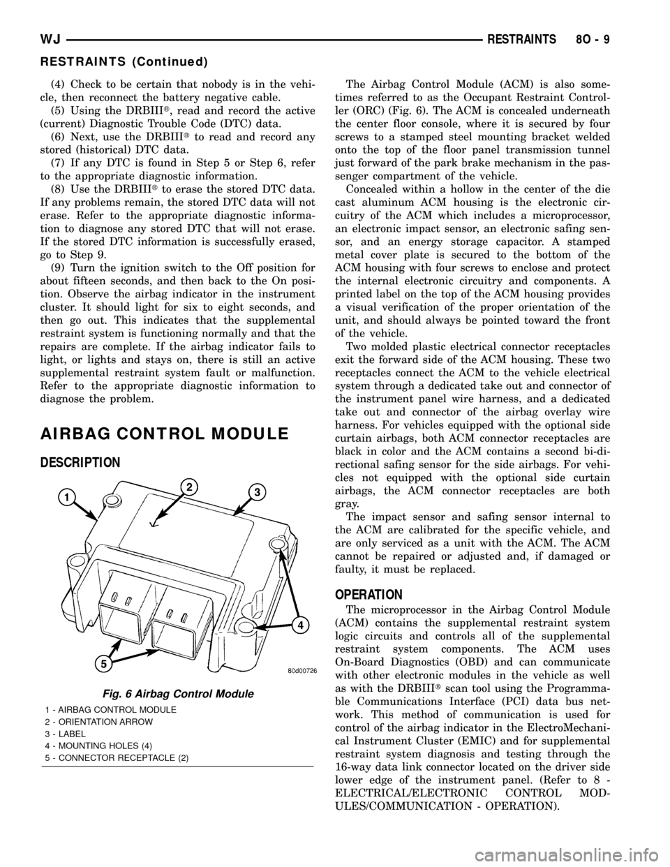
The Airbag Control Module (ACM) is also some-
times referred to as the Occupant Restraint Control-
ler (ORC) (Fig. 6). The ACM is concealed underneath
the center floor console, where it is secured by four
screws to a stamped steel mounting bracket welded
onto the top of the floor panel transmission tunnel
just forward of the park brake mechanism in the pas-
senger compartment of the vehicle.
Concealed within a hollow in the center of the die
cast aluminum ACM housing is the electronic cir-
cuitry of the ACM which includes a microprocessor,
an electronic impact sensor, an electronic safing sen-
sor, and an energy storage capacitor. A stamped
metal cover plate is secured to the bottom of the
ACM housing with four screws to enclose and protect
the internal electronic circuitry and components. A
printed label on the top of the ACM housing provides
a visual verification of the proper orientation of the
unit, and should always be pointed toward the front
of the vehicle.
Two molded plastic electrical connector receptacles
exit the forward side of the ACM housing. These two
receptacles connect the ACM to the vehicle electrical
system through a dedicated take out and connector of
the instrument panel wire harness, and a dedicated
take out and connector of the airbag overlay wire
harness. For vehicles equipped with the optional side
curtain airbags, both ACM connector receptacles are
black in color and the ACM contains a second bi-di-
rectional safing sensor for the side airbags. For vehi-
cles not equipped with the optional side curtain
airbags, the ACM connector receptacles are both
gray.
The impact sensor and safing sensor internal to
the ACM are calibrated for the specific vehicle, and
are only serviced as a unit with the ACM. The ACM
cannot be repaired or adjusted and, if damaged or
faulty, it must be replaced.
OPERATION
The microprocessor in the Airbag Control Module
(ACM) contains the supplemental restraint system
logic circuits and controls all of the supplemental
restraint system components. The ACM uses
On-Board Diagnostics (OBD) and can communicate
with other electronic modules in the vehicle as well
as with the DRBIIItscan tool using the Programma-
ble Communications Interface (PCI) data bus net-
work. This method of communication is used for
control of the airbag indicator in the ElectroMechani-
cal Instrument Cluster (EMIC) and for supplemental
restraint system diagnosis and testing through the
16-way data link connector located on the driver side
lower edge of the instrument panel. (Refer to 8 -
ELECTRICAL/ELECTRONIC CONTROL MOD-
ULES/COMMUNICATION - OPERATION).
Fig. 6 Airbag Control Module
1 - AIRBAG CONTROL MODULE
2 - ORIENTATION ARROW
3 - LABEL
4 - MOUNTING HOLES (4)
5 - CONNECTOR RECEPTACLE (2)
WJRESTRAINTS 8O - 9
RESTRAINTS (Continued)
Page 549 of 2199
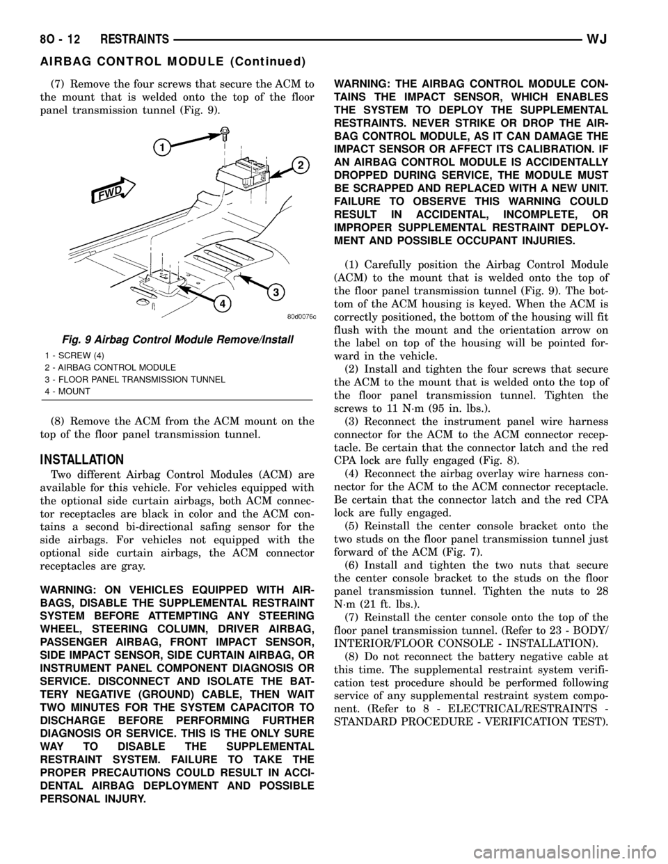
(7) Remove the four screws that secure the ACM to
the mount that is welded onto the top of the floor
panel transmission tunnel (Fig. 9).
(8) Remove the ACM from the ACM mount on the
top of the floor panel transmission tunnel.
INSTALLATION
Two different Airbag Control Modules (ACM) are
available for this vehicle. For vehicles equipped with
the optional side curtain airbags, both ACM connec-
tor receptacles are black in color and the ACM con-
tains a second bi-directional safing sensor for the
side airbags. For vehicles not equipped with the
optional side curtain airbags, the ACM connector
receptacles are gray.
WARNING: ON VEHICLES EQUIPPED WITH AIR-
BAGS, DISABLE THE SUPPLEMENTAL RESTRAINT
SYSTEM BEFORE ATTEMPTING ANY STEERING
WHEEL, STEERING COLUMN, DRIVER AIRBAG,
PASSENGER AIRBAG, FRONT IMPACT SENSOR,
SIDE IMPACT SENSOR, SIDE CURTAIN AIRBAG, OR
INSTRUMENT PANEL COMPONENT DIAGNOSIS OR
SERVICE. DISCONNECT AND ISOLATE THE BAT-
TERY NEGATIVE (GROUND) CABLE, THEN WAIT
TWO MINUTES FOR THE SYSTEM CAPACITOR TO
DISCHARGE BEFORE PERFORMING FURTHER
DIAGNOSIS OR SERVICE. THIS IS THE ONLY SURE
WAY TO DISABLE THE SUPPLEMENTAL
RESTRAINT SYSTEM. FAILURE TO TAKE THE
PROPER PRECAUTIONS COULD RESULT IN ACCI-
DENTAL AIRBAG DEPLOYMENT AND POSSIBLE
PERSONAL INJURY.WARNING: THE AIRBAG CONTROL MODULE CON-
TAINS THE IMPACT SENSOR, WHICH ENABLES
THE SYSTEM TO DEPLOY THE SUPPLEMENTAL
RESTRAINTS. NEVER STRIKE OR DROP THE AIR-
BAG CONTROL MODULE, AS IT CAN DAMAGE THE
IMPACT SENSOR OR AFFECT ITS CALIBRATION. IF
AN AIRBAG CONTROL MODULE IS ACCIDENTALLY
DROPPED DURING SERVICE, THE MODULE MUST
BE SCRAPPED AND REPLACED WITH A NEW UNIT.
FAILURE TO OBSERVE THIS WARNING COULD
RESULT IN ACCIDENTAL, INCOMPLETE, OR
IMPROPER SUPPLEMENTAL RESTRAINT DEPLOY-
MENT AND POSSIBLE OCCUPANT INJURIES.
(1) Carefully position the Airbag Control Module
(ACM) to the mount that is welded onto the top of
the floor panel transmission tunnel (Fig. 9). The bot-
tom of the ACM housing is keyed. When the ACM is
correctly positioned, the bottom of the housing will fit
flush with the mount and the orientation arrow on
the label on top of the housing will be pointed for-
ward in the vehicle.
(2) Install and tighten the four screws that secure
the ACM to the mount that is welded onto the top of
the floor panel transmission tunnel. Tighten the
screws to 11 N´m (95 in. lbs.).
(3) Reconnect the instrument panel wire harness
connector for the ACM to the ACM connector recep-
tacle. Be certain that the connector latch and the red
CPA lock are fully engaged (Fig. 8).
(4) Reconnect the airbag overlay wire harness con-
nector for the ACM to the ACM connector receptacle.
Be certain that the connector latch and the red CPA
lock are fully engaged.
(5) Reinstall the center console bracket onto the
two studs on the floor panel transmission tunnel just
forward of the ACM (Fig. 7).
(6) Install and tighten the two nuts that secure
the center console bracket to the studs on the floor
panel transmission tunnel. Tighten the nuts to 28
N´m (21 ft. lbs.).
(7) Reinstall the center console onto the top of the
floor panel transmission tunnel. (Refer to 23 - BODY/
INTERIOR/FLOOR CONSOLE - INSTALLATION).
(8) Do not reconnect the battery negative cable at
this time. The supplemental restraint system verifi-
cation test procedure should be performed following
service of any supplemental restraint system compo-
nent. (Refer to 8 - ELECTRICAL/RESTRAINTS -
STANDARD PROCEDURE - VERIFICATION TEST).
Fig. 9 Airbag Control Module Remove/Install
1 - SCREW (4)
2 - AIRBAG CONTROL MODULE
3 - FLOOR PANEL TRANSMISSION TUNNEL
4 - MOUNT
8O - 12 RESTRAINTSWJ
AIRBAG CONTROL MODULE (Continued)
Page 623 of 2199
(3) Insert the hook formation on the tip of the
wiper arm through the opening in the wiper blade
superstructure ahead of the wiper blade pivot block/
latch unit far enough to engage the pivot block with
the hook (Fig. 10).
(4) Slide the wiper blade pivot block/latch up into
the hook formation on the tip of the wiper arm until
the latch release tab snaps into its locked position.
Latch engagement will be accompanied by an audible
click.
(5) Gently lower the wiper blade onto the glass.
FRONT WIPER MODULE
DESCRIPTION
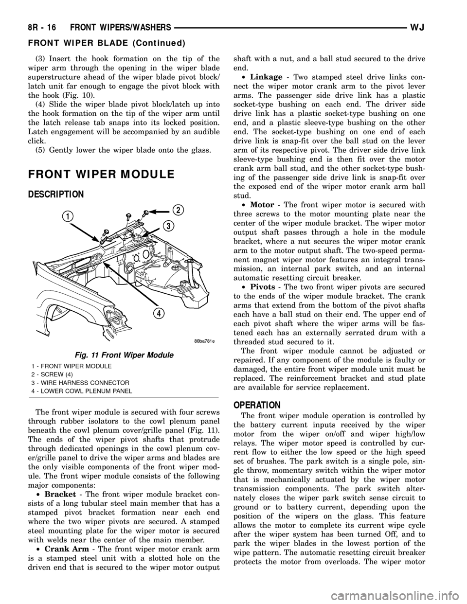
The front wiper module is secured with four screws
through rubber isolators to the cowl plenum panel
beneath the cowl plenum cover/grille panel (Fig. 11).
The ends of the wiper pivot shafts that protrude
through dedicated openings in the cowl plenum cov-
er/grille panel to drive the wiper arms and blades are
the only visible components of the front wiper mod-
ule. The front wiper module consists of the following
major components:
²Bracket- The front wiper module bracket con-
sists of a long tubular steel main member that has a
stamped pivot bracket formation near each end
where the two wiper pivots are secured. A stamped
steel mounting plate for the wiper motor is secured
with welds near the center of the main member.
²Crank Arm- The front wiper motor crank arm
is a stamped steel unit with a slotted hole on the
driven end that is secured to the wiper motor outputshaft with a nut, and a ball stud secured to the drive
end.
²Linkage- Two stamped steel drive links con-
nect the wiper motor crank arm to the pivot lever
arms. The passenger side drive link has a plastic
socket-type bushing on each end. The driver side
drive link has a plastic socket-type bushing on one
end, and a plastic sleeve-type bushing on the other
end. The socket-type bushing on one end of each
drive link is snap-fit over the ball stud on the lever
arm of its respective pivot. The driver side drive link
sleeve-type bushing end is then fit over the motor
crank arm ball stud, and the other socket-type bush-
ing of the passenger side drive link is snap-fit over
the exposed end of the wiper motor crank arm ball
stud.
²Motor- The front wiper motor is secured with
three screws to the motor mounting plate near the
center of the wiper module bracket. The wiper motor
output shaft passes through a hole in the module
bracket, where a nut secures the wiper motor crank
arm to the motor output shaft. The two-speed perma-
nent magnet wiper motor features an integral trans-
mission, an internal park switch, and an internal
automatic resetting circuit breaker.
²Pivots- The two front wiper pivots are secured
to the ends of the wiper module bracket. The crank
arms that extend from the bottom of the pivot shafts
each have a ball stud on their end. The upper end of
each pivot shaft where the wiper arms will be fas-
tened each has an externally serrated drum with a
threaded stud secured to it.
The front wiper module cannot be adjusted or
repaired. If any component of the module is faulty or
damaged, the entire front wiper module unit must be
replaced. The reinforcement bracket and stud plate
are available for service replacement.OPERATION
The front wiper module operation is controlled by
the battery current inputs received by the wiper
motor from the wiper on/off and wiper high/low
relays. The wiper motor speed is controlled by cur-
rent flow to either the low speed or the high speed
set of brushes. The park switch is a single pole, sin-
gle throw, momentary switch within the wiper motor
that is mechanically actuated by the wiper motor
transmission components. The park switch alter-
nately closes the wiper park switch sense circuit to
ground or to battery current, depending upon the
position of the wipers on the glass. This feature
allows the motor to complete its current wipe cycle
after the wiper system has been turned Off, and to
park the wiper blades in the lowest portion of the
wipe pattern. The automatic resetting circuit breaker
protects the motor from overloads. The wiper motor
Fig. 11 Front Wiper Module
1 - FRONT WIPER MODULE
2 - SCREW (4)
3 - WIRE HARNESS CONNECTOR
4 - LOWER COWL PLENUM PANEL
8R - 16 FRONT WIPERS/WASHERSWJ
FRONT WIPER BLADE (Continued)
Page 1331 of 2199
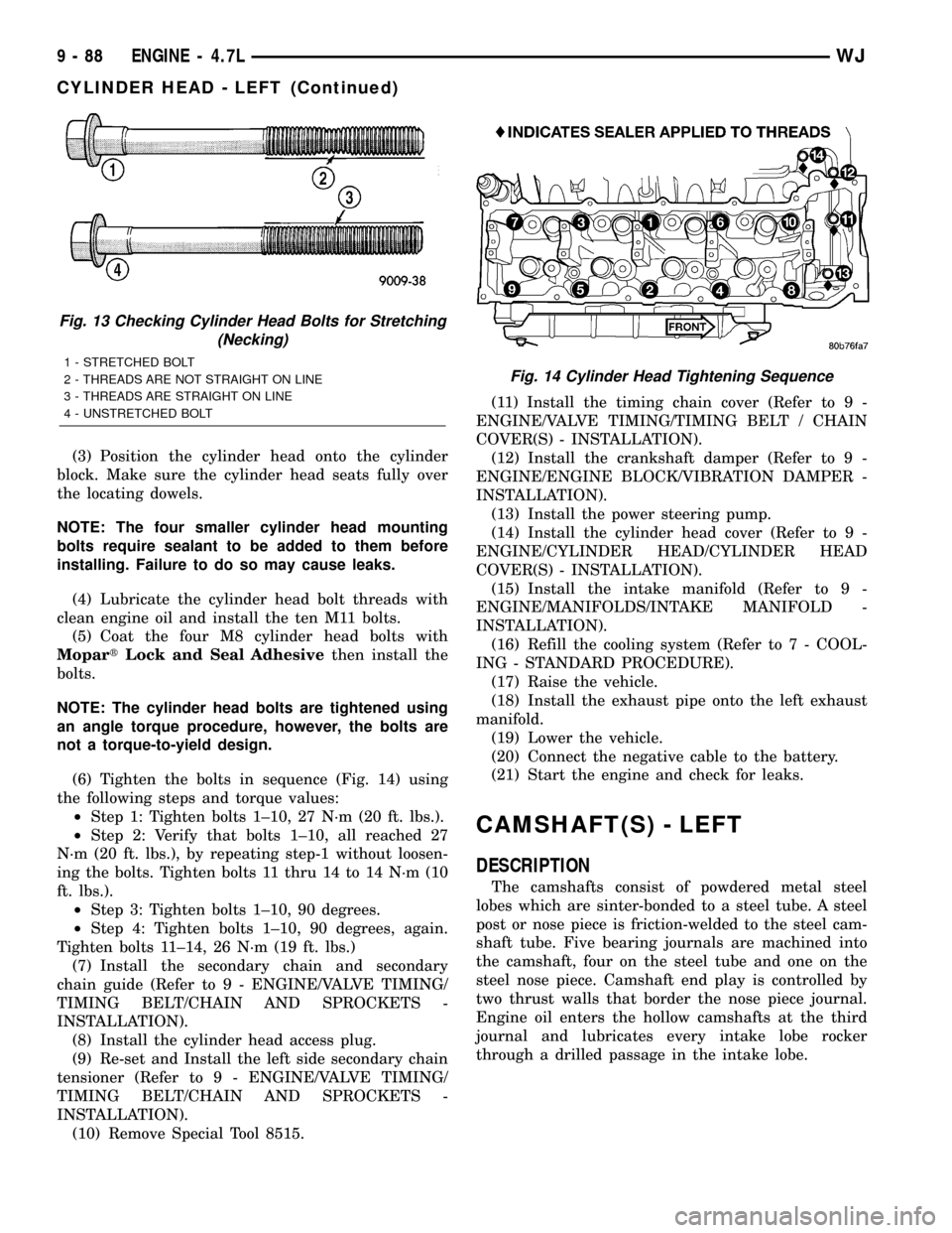
(3) Position the cylinder head onto the cylinder
block. Make sure the cylinder head seats fully over
the locating dowels.
NOTE: The four smaller cylinder head mounting
bolts require sealant to be added to them before
installing. Failure to do so may cause leaks.
(4) Lubricate the cylinder head bolt threads with
clean engine oil and install the ten M11 bolts.
(5) Coat the four M8 cylinder head bolts with
MopartLock and Seal Adhesivethen install the
bolts.
NOTE: The cylinder head bolts are tightened using
an angle torque procedure, however, the bolts are
not a torque-to-yield design.
(6) Tighten the bolts in sequence (Fig. 14) using
the following steps and torque values:
²Step 1: Tighten bolts 1±10, 27 N´m (20 ft. lbs.).
²Step 2: Verify that bolts 1±10, all reached 27
N´m (20 ft. lbs.), by repeating step-1 without loosen-
ing the bolts. Tighten bolts 11 thru 14 to 14 N´m (10
ft. lbs.).
²Step 3: Tighten bolts 1±10, 90 degrees.
²Step 4: Tighten bolts 1±10, 90 degrees, again.
Tighten bolts 11±14, 26 N´m (19 ft. lbs.)
(7) Install the secondary chain and secondary
chain guide (Refer to 9 - ENGINE/VALVE TIMING/
TIMING BELT/CHAIN AND SPROCKETS -
INSTALLATION).
(8) Install the cylinder head access plug.
(9) Re-set and Install the left side secondary chain
tensioner (Refer to 9 - ENGINE/VALVE TIMING/
TIMING BELT/CHAIN AND SPROCKETS -
INSTALLATION).
(10) Remove Special Tool 8515.(11) Install the timing chain cover (Refer to 9 -
ENGINE/VALVE TIMING/TIMING BELT / CHAIN
COVER(S) - INSTALLATION).
(12) Install the crankshaft damper (Refer to 9 -
ENGINE/ENGINE BLOCK/VIBRATION DAMPER -
INSTALLATION).
(13) Install the power steering pump.
(14) Install the cylinder head cover (Refer to 9 -
ENGINE/CYLINDER HEAD/CYLINDER HEAD
COVER(S) - INSTALLATION).
(15) Install the intake manifold (Refer to 9 -
ENGINE/MANIFOLDS/INTAKE MANIFOLD -
INSTALLATION).
(16) Refill the cooling system (Refer to 7 - COOL-
ING - STANDARD PROCEDURE).
(17) Raise the vehicle.
(18) Install the exhaust pipe onto the left exhaust
manifold.
(19) Lower the vehicle.
(20) Connect the negative cable to the battery.
(21) Start the engine and check for leaks.
CAMSHAFT(S) - LEFT
DESCRIPTION
The camshafts consist of powdered metal steel
lobes which are sinter-bonded to a steel tube. A steel
post or nose piece is friction-welded to the steel cam-
shaft tube. Five bearing journals are machined into
the camshaft, four on the steel tube and one on the
steel nose piece. Camshaft end play is controlled by
two thrust walls that border the nose piece journal.
Engine oil enters the hollow camshafts at the third
journal and lubricates every intake lobe rocker
through a drilled passage in the intake lobe.
Fig. 13 Checking Cylinder Head Bolts for Stretching
(Necking)
1 - STRETCHED BOLT
2 - THREADS ARE NOT STRAIGHT ON LINE
3 - THREADS ARE STRAIGHT ON LINE
4 - UNSTRETCHED BOLTFig. 14 Cylinder Head Tightening Sequence
9 - 88 ENGINE - 4.7LWJ
CYLINDER HEAD - LEFT (Continued)
Page 1343 of 2199
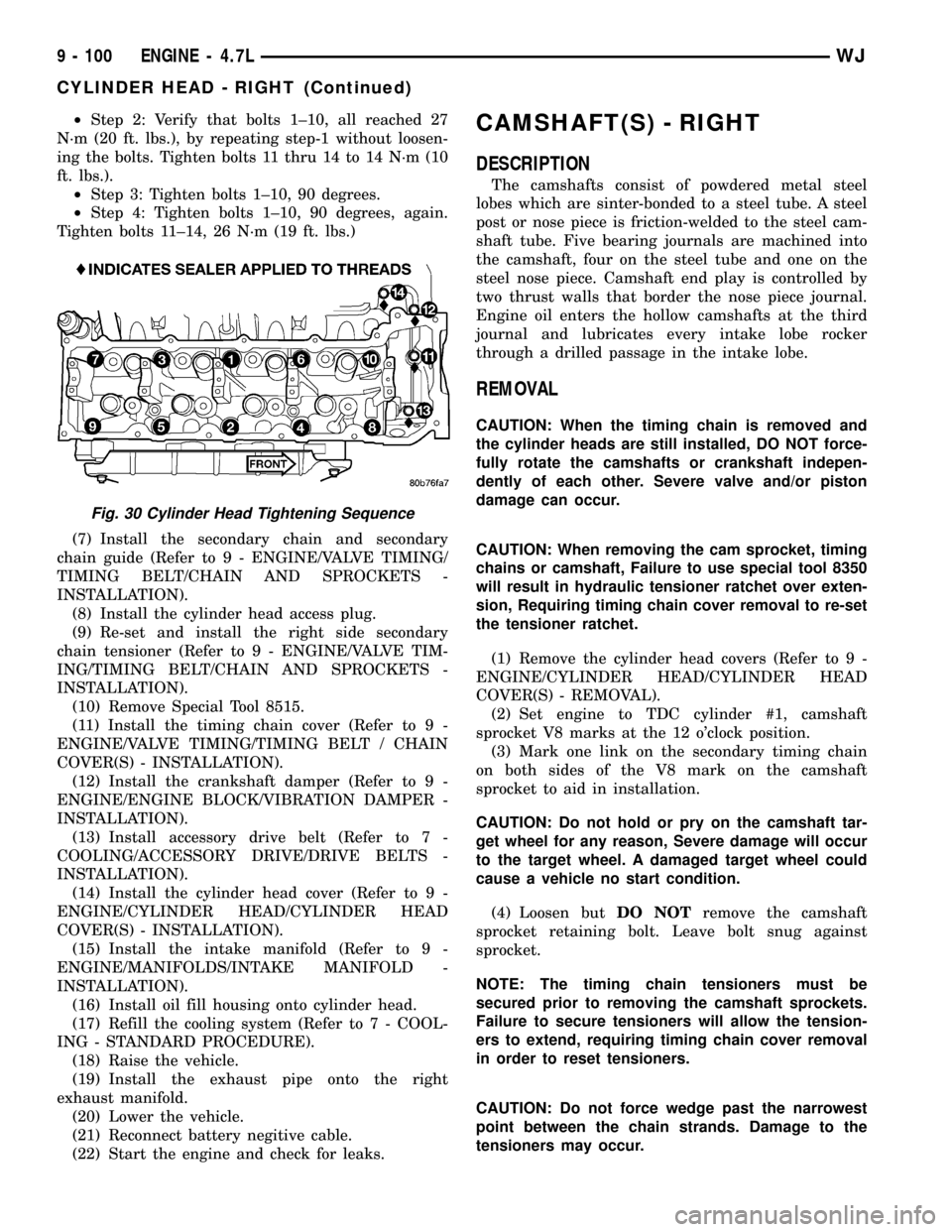
²Step 2: Verify that bolts 1±10, all reached 27
N´m (20 ft. lbs.), by repeating step-1 without loosen-
ing the bolts. Tighten bolts 11 thru 14 to 14 N´m (10
ft. lbs.).
²Step 3: Tighten bolts 1±10, 90 degrees.
²Step 4: Tighten bolts 1±10, 90 degrees, again.
Tighten bolts 11±14, 26 N´m (19 ft. lbs.)
(7) Install the secondary chain and secondary
chain guide (Refer to 9 - ENGINE/VALVE TIMING/
TIMING BELT/CHAIN AND SPROCKETS -
INSTALLATION).
(8) Install the cylinder head access plug.
(9) Re-set and install the right side secondary
chain tensioner (Refer to 9 - ENGINE/VALVE TIM-
ING/TIMING BELT/CHAIN AND SPROCKETS -
INSTALLATION).
(10) Remove Special Tool 8515.
(11) Install the timing chain cover (Refer to 9 -
ENGINE/VALVE TIMING/TIMING BELT / CHAIN
COVER(S) - INSTALLATION).
(12) Install the crankshaft damper (Refer to 9 -
ENGINE/ENGINE BLOCK/VIBRATION DAMPER -
INSTALLATION).
(13) Install accessory drive belt (Refer to 7 -
COOLING/ACCESSORY DRIVE/DRIVE BELTS -
INSTALLATION).
(14) Install the cylinder head cover (Refer to 9 -
ENGINE/CYLINDER HEAD/CYLINDER HEAD
COVER(S) - INSTALLATION).
(15) Install the intake manifold (Refer to 9 -
ENGINE/MANIFOLDS/INTAKE MANIFOLD -
INSTALLATION).
(16) Install oil fill housing onto cylinder head.
(17) Refill the cooling system (Refer to 7 - COOL-
ING - STANDARD PROCEDURE).
(18) Raise the vehicle.
(19) Install the exhaust pipe onto the right
exhaust manifold.
(20) Lower the vehicle.
(21) Reconnect battery negitive cable.
(22) Start the engine and check for leaks.CAMSHAFT(S) - RIGHT
DESCRIPTION
The camshafts consist of powdered metal steel
lobes which are sinter-bonded to a steel tube. A steel
post or nose piece is friction-welded to the steel cam-
shaft tube. Five bearing journals are machined into
the camshaft, four on the steel tube and one on the
steel nose piece. Camshaft end play is controlled by
two thrust walls that border the nose piece journal.
Engine oil enters the hollow camshafts at the third
journal and lubricates every intake lobe rocker
through a drilled passage in the intake lobe.
REMOVAL
CAUTION: When the timing chain is removed and
the cylinder heads are still installed, DO NOT force-
fully rotate the camshafts or crankshaft indepen-
dently of each other. Severe valve and/or piston
damage can occur.
CAUTION: When removing the cam sprocket, timing
chains or camshaft, Failure to use special tool 8350
will result in hydraulic tensioner ratchet over exten-
sion, Requiring timing chain cover removal to re-set
the tensioner ratchet.
(1) Remove the cylinder head covers (Refer to 9 -
ENGINE/CYLINDER HEAD/CYLINDER HEAD
COVER(S) - REMOVAL).
(2) Set engine to TDC cylinder #1, camshaft
sprocket V8 marks at the 12 o'clock position.
(3) Mark one link on the secondary timing chain
on both sides of the V8 mark on the camshaft
sprocket to aid in installation.
CAUTION: Do not hold or pry on the camshaft tar-
get wheel for any reason, Severe damage will occur
to the target wheel. A damaged target wheel could
cause a vehicle no start condition.
(4) Loosen butDO NOTremove the camshaft
sprocket retaining bolt. Leave bolt snug against
sprocket.
NOTE: The timing chain tensioners must be
secured prior to removing the camshaft sprockets.
Failure to secure tensioners will allow the tension-
ers to extend, requiring timing chain cover removal
in order to reset tensioners.
CAUTION: Do not force wedge past the narrowest
point between the chain strands. Damage to the
tensioners may occur.
Fig. 30 Cylinder Head Tightening Sequence
9 - 100 ENGINE - 4.7LWJ
CYLINDER HEAD - RIGHT (Continued)