door handle JEEP GRAND CHEROKEE 2002 WJ / 2.G User Guide
[x] Cancel search | Manufacturer: JEEP, Model Year: 2002, Model line: GRAND CHEROKEE, Model: JEEP GRAND CHEROKEE 2002 WJ / 2.GPages: 2199, PDF Size: 76.01 MB
Page 1051 of 2199

Component Page
LIFTGATE FLIP-UP PUSH
BUTTON SWITCH................ 8W-80-97
LIFTGATE FLIP-UP RELEASE
SOLENOID...................... 8W-80-97
LIFTGATE POWER LOCK MOTOR..... 8W-80-97
LINE PRESSURE SENSOR (4.7L)...... 8W-80-98
MANIFOLD ABSOLUTE PRESSURE
SENSOR (4.0L)................... 8W-80-98
MANIFOLD ABSOLUTE PRESSURE
SENSOR (4.7L)................... 8W-80-98
MANUAL TEMPERATURE
CONTROL C1 (MTC).............. 8W-80-98
MANUAL TEMPERATURE
CONTROL C2 (MTC).............. 8W-80-99
MASS AIR FLOW SENSOR (DIESEL) . . . 8W-80-99
MODE DOOR MOTOR/ACTUATOR
(AZC).......................... 8W-80-99
NEEDLE MOVEMENT SENSOR
(DIESEL)....................... 8W-80-99
OUTPUT SPEED SENSOR (4.0L)...... 8W-80-99
OUTPUT SPEED SENSOR (4.7L)..... 8W-80-100
OVERHEAD MAP/COURTESY LAMP . . 8W-80-100
OXYGEN SENSOR 1/1 UPSTREAM.... 8W-80-100
OXYGEN SENSOR 1/2 DOWNSTREAM . 8W-80-100
OXYGEN SENSOR 2/1 UPSTREAM.... 8W-80-100
OXYGEN SENSOR 2/2
DOWNSTREAM................. 8W-80-101
PARK/NEUTRAL POSITION SWITCH
(4.0L).......................... 8W-80-101
PARK/NEUTRAL POSITION SWITCH
(DIESEL)...................... 8W-80-101
PASSENGER AIRBAG.............. 8W-80-101
PASSENGER BLEND DOOR
MOTOR/ACTUATOR (LHD) (AZC) . . . 8W-80-101
PASSENGER BLEND DOOR
MOTOR/ACTUATOR (RHD) (AZC) . . . 8W-80-102
PASSENGER CURTAIN AIRBAG...... 8W-80-102
PASSENGER DOOR LOCK MOTOR/AJAR
SWITCH....................... 8W-80-102
PASSENGER DOOR MODULE C1..... 8W-80-102
PASSENGER DOOR MODULE C2..... 8W-80-103
PASSENGER FRONT DOOR
COURTESY LAMP............... 8W-80-103
PASSENGER FRONT POWER
WINDOW MOTOR............... 8W-80-103
PASSENGER HEATED SEAT BACK
(PREMIUM I/III)................. 8W-80-103
PASSENGER HEATED SEAT CUSHION
(PREMIUM I/III)................. 8W-80-104
PASSENGER HEATED SEAT SWITCH . 8W-80-104
PASSENGER LUMBAR MOTOR
(MIDLINE/PREMIUM)............ 8W-80-104
PASSENGER LUMBAR SWITCH
(MIDLINE/PREMIUM)............ 8W-80-104
PASSENGER POWER MIRROR....... 8W-80-105Component Page
PASSENGER POWER SEAT FRONT
RISER MOTOR.................. 8W-80-105
PASSENGER POWER SEAT
HORIZONTAL MOTOR........... 8W-80-105
PASSENGER POWER SEAT REAR
RISER MOTOR.................. 8W-80-105
PASSENGER POWER SEAT RECLINER
MOTOR (MIDLINE/PREMIUM)..... 8W-80-106
PASSENGER POWER SEAT SWITCH
(MIDLINE/PREMIUM)............ 8W-80-106
PASSENGER REAR POWER
WINDOW MOTOR............... 8W-80-106
PASSENGER REAR POWER
WINDOW SWITCH............... 8W-80-106
PASSENGER SEAT BELT SWITCH.... 8W-80-106
PASSENGER SIDE IMPACT
SENSOR....................... 8W-80-107
POWER AMPLIFIER C1
(PREMIUM RADIO).............. 8W-80-107
POWER AMPLIFIER C2
(PREMIUM RADIO).............. 8W-80-107
POWER CONNECTOR.............. 8W-80-108
POWERTRAIN CONTROL
MODULE C1 (GAS).............. 8W-80-108
POWERTRAIN CONTROL
MODULE C2 (GAS).............. 8W-80-109
POWERTRAIN CONTROL
MODULE C3 (GAS).............. 8W-80-110
RADIATOR FAN MOTOR............ 8W-80-110
RADIATOR FAN RELAY............. 8W-80-111
RADIO C1........................ 8W-80-111
RADIO C2........................ 8W-80-111
RAIN SENSOR (AUTOWIPE)......... 8W-80-112
REAR POWER OUTLET............. 8W-80-112
REAR WASHER PUMP.............. 8W-80-112
REAR WIPER MOTOR.............. 8W-80-112
RECIRCULATION DOOR
MOTOR/ACTUATOR (AZC)......... 8W-80-112
RED BRAKE WARNING INDICATOR
SWITCH....................... 8W-80-113
REMOTE KEYLESS MODULE
(JAPAN)....................... 8W-80-113
RIGHT COURTESY LAMP........... 8W-80-113
RIGHT DOOR HANDLE
COURTESY LAMP............... 8W-80-113
RIGHT FOG LAMP................. 8W-80-113
RIGHT FRONT DOOR SPEAKER..... 8W-80-114
RIGHT FRONT IMPACT SENSOR..... 8W-80-114
RIGHT FRONT PARK LAMP......... 8W-80-114
RIGHT FRONT PARK/TURN SIGNAL LAMP
(EXCEPT BUILT-UP-EXPORT)...... 8W-80-114
RIGHT FRONT SIDE MARKER LAMP
(EXCEPT BUILT-UP-EXPORT)...... 8W-80-115
RIGHT FRONT TURN SIGNAL LAMP
(BUILT-UP-EXPORT)............. 8W-80-115
8W - 80 - 4 8W-80 CONNECTOR PIN-OUTWJ
Page 1139 of 2199
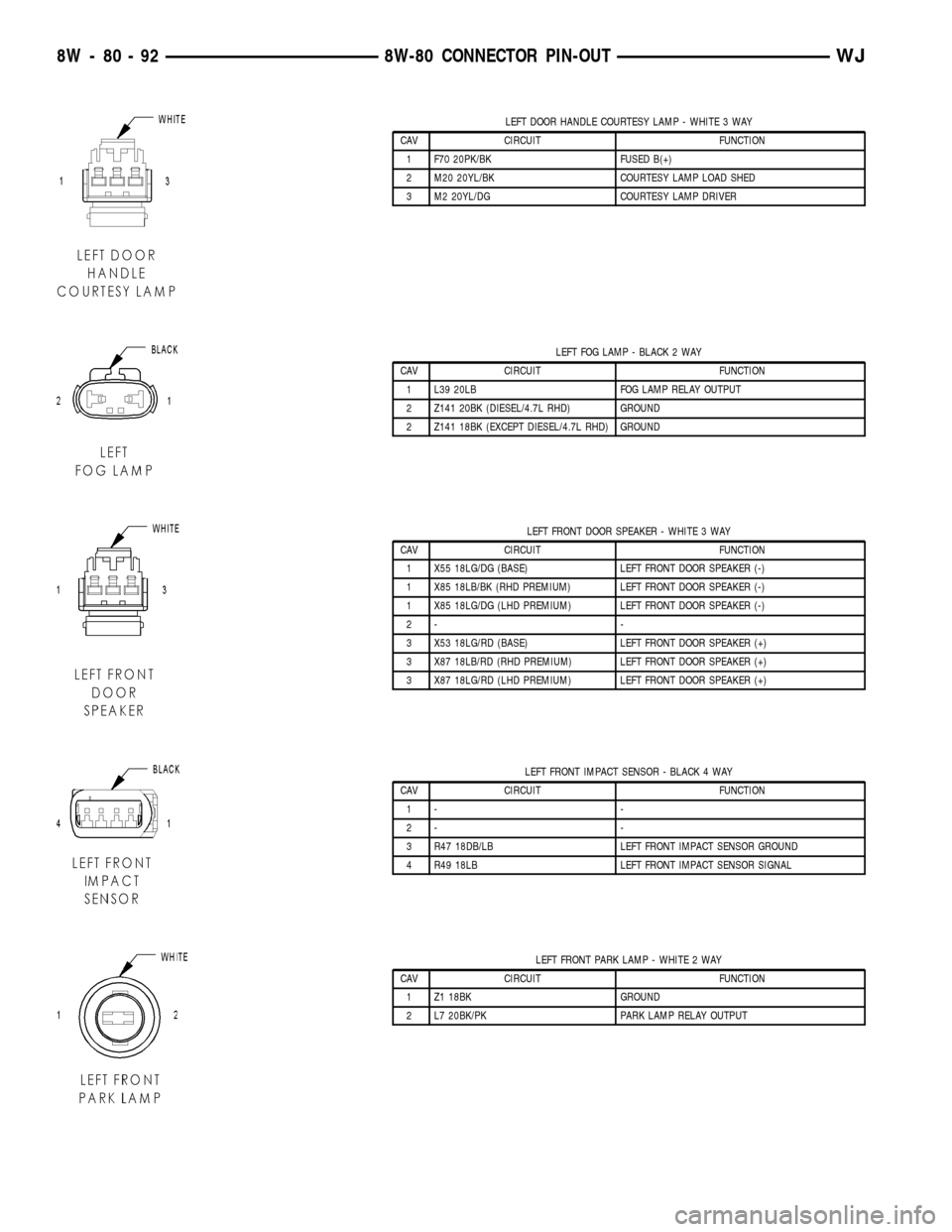
LEFT DOOR HANDLE COURTESY LAMP - WHITE 3 WAY
CAV CIRCUIT FUNCTION
1 F70 20PK/BK FUSED B(+)
2 M20 20YL/BK COURTESY LAMP LOAD SHED
3 M2 20YL/DG COURTESY LAMP DRIVER
LEFT FOG LAMP - BLACK 2 WAY
CAV CIRCUIT FUNCTION
1 L39 20LB FOG LAMP RELAY OUTPUT
2 Z141 20BK (DIESEL/4.7L RHD) GROUND
2 Z141 18BK (EXCEPT DIESEL/4.7L RHD) GROUND
LEFT FRONT DOOR SPEAKER - WHITE 3 WAY
CAV CIRCUIT FUNCTION
1 X55 18LG/DG (BASE) LEFT FRONT DOOR SPEAKER (-)
1 X85 18LB/BK (RHD PREMIUM) LEFT FRONT DOOR SPEAKER (-)
1 X85 18LG/DG (LHD PREMIUM) LEFT FRONT DOOR SPEAKER (-)
2- -
3 X53 18LG/RD (BASE) LEFT FRONT DOOR SPEAKER (+)
3 X87 18LB/RD (RHD PREMIUM) LEFT FRONT DOOR SPEAKER (+)
3 X87 18LG/RD (LHD PREMIUM) LEFT FRONT DOOR SPEAKER (+)
LEFT FRONT IMPACT SENSOR - BLACK 4 WAY
CAV CIRCUIT FUNCTION
1- -
2- -
3 R47 18DB/LB LEFT FRONT IMPACT SENSOR GROUND
4 R49 18LB LEFT FRONT IMPACT SENSOR SIGNAL
LEFT FRONT PARK LAMP - WHITE 2 WAY
CAV CIRCUIT FUNCTION
1 Z1 18BK GROUND
2 L7 20BK/PK PARK LAMP RELAY OUTPUT
8W - 80 - 92 8W-80 CONNECTOR PIN-OUTWJ
Page 1160 of 2199
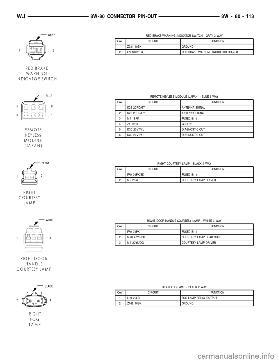
RED BRAKE WARNING INDICATOR SWITCH - GRAY 2 WAY
CAV CIRCUIT FUNCTION
1 Z231 18BK GROUND
2 G9 18GY/BK RED BRAKE WARNING INDICATOR DRIVER
REMOTE KEYLESS MODULE (JAPAN) - BLUE 6 WAY
CAV CIRCUIT FUNCTION
1 K25 20RD/GY ANTENNA SIGNAL
2 K25 20RD/GY ANTENNA SIGNAL
3 M1 18PK FUSED B(+)
4 Z1 18BK GROUND
5 D30 20VT/YL DIAGNOSTIC OUT
6 D30 20VT/YL DIAGNOSTIC OUT
RIGHT COURTESY LAMP - BLACK 2 WAY
CAV CIRCUIT FUNCTION
1 F70 20PK/BK FUSED B(+)
2 M2 20YL COURTESY LAMP DRIVER
RIGHT DOOR HANDLE COURTESY LAMP - WHITE 3 WAY
CAV CIRCUIT FUNCTION
1 F70 20PK FUSED B(+)
2 M20 20YL/BK COURTESY LAMP LOAD SHED
3 M2 20YL/DG COURTESY LAMP DRIVER
RIGHT FOG LAMP - BLACK 2 WAY
CAV CIRCUIT FUNCTION
1 L39 20LB FOG LAMP RELAY OUTPUT
2 Z142 18BK GROUND
WJ8W-80 CONNECTOR PIN-OUT 8W - 80 - 113
Page 1181 of 2199
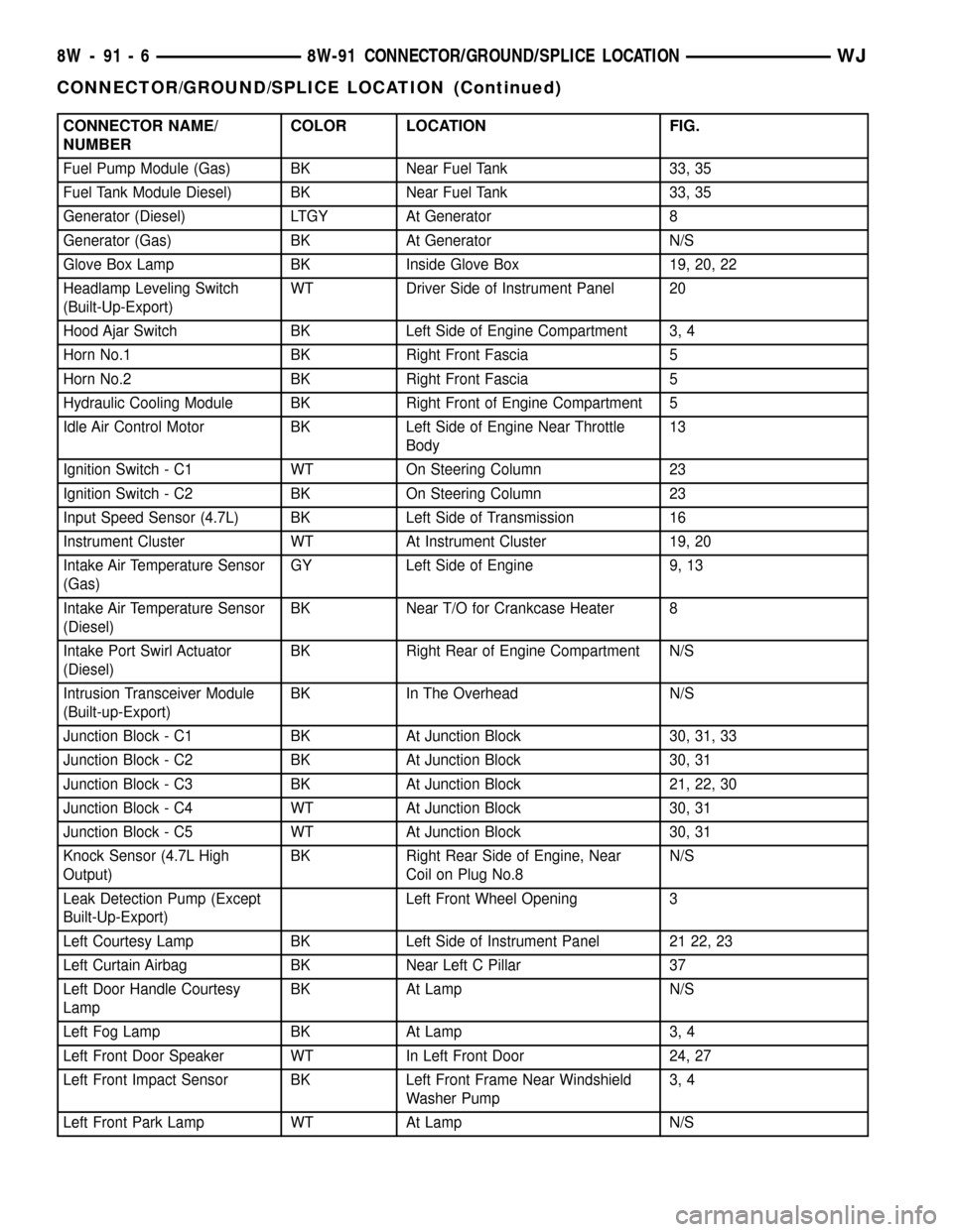
CONNECTOR NAME/
NUMBERCOLOR LOCATION FIG.
Fuel Pump Module (Gas) BK Near Fuel Tank 33, 35
Fuel Tank Module Diesel) BK Near Fuel Tank 33, 35
Generator (Diesel) LTGY At Generator 8
Generator (Gas) BK At Generator N/S
Glove Box Lamp BK Inside Glove Box 19, 20, 22
Headlamp Leveling Switch
(Built-Up-Export)WT Driver Side of Instrument Panel 20
Hood Ajar Switch BK Left Side of Engine Compartment 3, 4
Horn No.1 BK Right Front Fascia 5
Horn No.2 BK Right Front Fascia 5
Hydraulic Cooling Module BK Right Front of Engine Compartment 5
Idle Air Control Motor BK Left Side of Engine Near Throttle
Body13
Ignition Switch - C1 WT On Steering Column 23
Ignition Switch - C2 BK On Steering Column 23
Input Speed Sensor (4.7L) BK Left Side of Transmission 16
Instrument Cluster WT At Instrument Cluster 19, 20
Intake Air Temperature Sensor
(Gas)GY Left Side of Engine 9, 13
Intake Air Temperature Sensor
(Diesel)BK Near T/O for Crankcase Heater 8
Intake Port Swirl Actuator
(Diesel)BK Right Rear of Engine Compartment N/S
Intrusion Transceiver Module
(Built-up-Export)BK In The Overhead N/S
Junction Block - C1 BK At Junction Block 30, 31, 33
Junction Block - C2 BK At Junction Block 30, 31
Junction Block - C3 BK At Junction Block 21, 22, 30
Junction Block - C4 WT At Junction Block 30, 31
Junction Block - C5 WT At Junction Block 30, 31
Knock Sensor (4.7L High
Output)BK Right Rear Side of Engine, Near
Coil on Plug No.8N/S
Leak Detection Pump (Except
Built-Up-Export)Left Front Wheel Opening 3
Left Courtesy Lamp BK Left Side of Instrument Panel 21 22, 23
Left Curtain Airbag BK Near Left C Pillar 37
Left Door Handle Courtesy
LampBK At Lamp N/S
Left Fog Lamp BK At Lamp 3, 4
Left Front Door Speaker WT In Left Front Door 24, 27
Left Front Impact Sensor BK Left Front Frame Near Windshield
Washer Pump3, 4
Left Front Park Lamp WT At Lamp N/S
8W - 91 - 6 8W-91 CONNECTOR/GROUND/SPLICE LOCATIONWJ
CONNECTOR/GROUND/SPLICE LOCATION (Continued)
Page 1184 of 2199
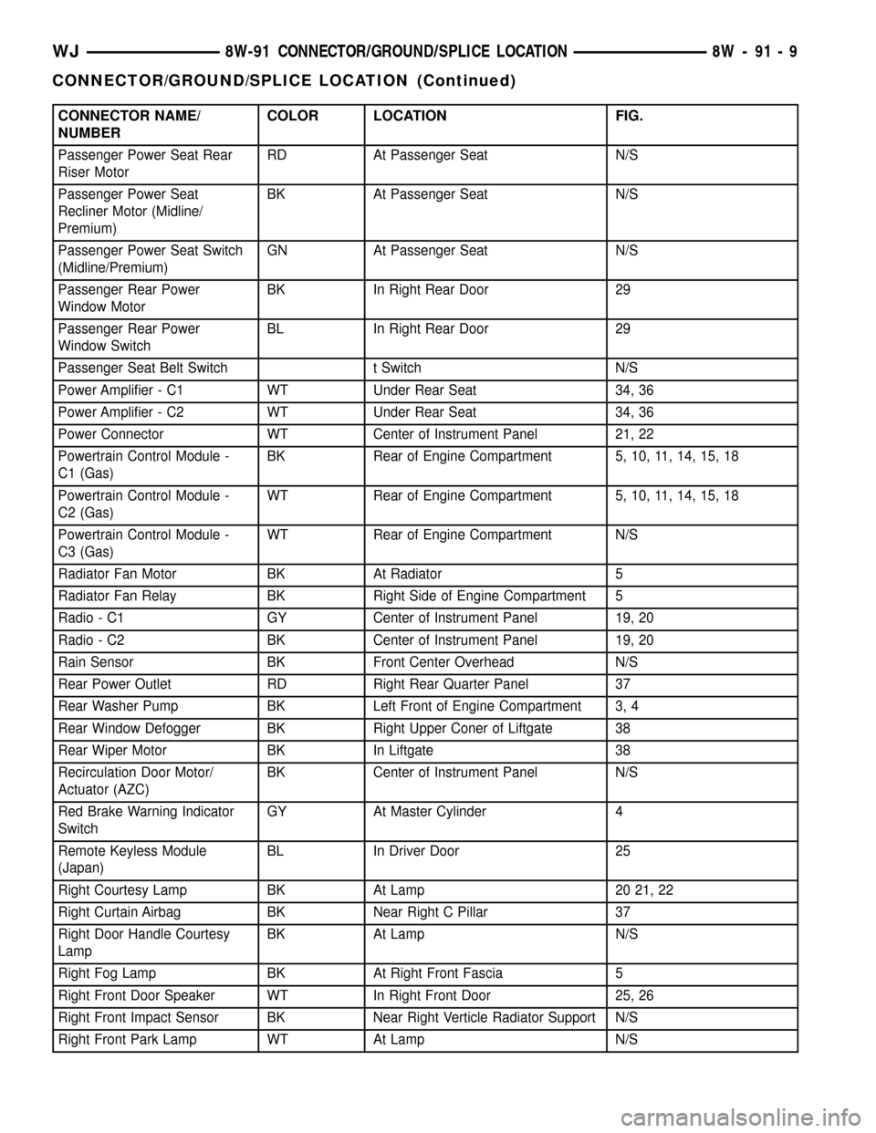
CONNECTOR NAME/
NUMBERCOLOR LOCATION FIG.
Passenger Power Seat Rear
Riser MotorRD At Passenger Seat N/S
Passenger Power Seat
Recliner Motor (Midline/
Premium)BK At Passenger Seat N/S
Passenger Power Seat Switch
(Midline/Premium)GN At Passenger Seat N/S
Passenger Rear Power
Window MotorBK In Right Rear Door 29
Passenger Rear Power
Window SwitchBL In Right Rear Door 29
Passenger Seat Belt Switch t Switch N/S
Power Amplifier - C1 WT Under Rear Seat 34, 36
Power Amplifier - C2 WT Under Rear Seat 34, 36
Power Connector WT Center of Instrument Panel 21, 22
Powertrain Control Module -
C1 (Gas)BK Rear of Engine Compartment 5, 10, 11, 14, 15, 18
Powertrain Control Module -
C2 (Gas)WT Rear of Engine Compartment 5, 10, 11, 14, 15, 18
Powertrain Control Module -
C3 (Gas)WT Rear of Engine Compartment N/S
Radiator Fan Motor BK At Radiator 5
Radiator Fan Relay BK Right Side of Engine Compartment 5
Radio - C1 GY Center of Instrument Panel 19, 20
Radio - C2 BK Center of Instrument Panel 19, 20
Rain Sensor BK Front Center Overhead N/S
Rear Power Outlet RD Right Rear Quarter Panel 37
Rear Washer Pump BK Left Front of Engine Compartment 3, 4
Rear Window Defogger BK Right Upper Coner of Liftgate 38
Rear Wiper Motor BK In Liftgate 38
Recirculation Door Motor/
Actuator (AZC)BK Center of Instrument Panel N/S
Red Brake Warning Indicator
SwitchGY At Master Cylinder 4
Remote Keyless Module
(Japan)BL In Driver Door 25
Right Courtesy Lamp BK At Lamp 20 21, 22
Right Curtain Airbag BK Near Right C Pillar 37
Right Door Handle Courtesy
LampBK At Lamp N/S
Right Fog Lamp BK At Right Front Fascia 5
Right Front Door Speaker WT In Right Front Door 25, 26
Right Front Impact Sensor BK Near Right Verticle Radiator Support N/S
Right Front Park Lamp WT At Lamp N/S
WJ8W-91 CONNECTOR/GROUND/SPLICE LOCATION 8W - 91 - 9
CONNECTOR/GROUND/SPLICE LOCATION (Continued)
Page 1876 of 2199
(2) Apply silicone lubricant to a cloth and wipe it
on door seals to avoid over-spray that can soil pas-
senger's clothing.
(3) Before applying lubricant, the component
should be wiped clean. After lubrication, any excess
lubricant should be removed.
(4) The hood latch, latch release mechanism, latch
striker, and safety latch should be lubricated period-
ically.
(5) The door lock cylinders should be lubricated
twice each year (preferably autumn and spring).
(a) Spray a small amount of lock cylinder lubri-
cant directly into the lock cylinder.
(b) Apply a small amount to the key and insert
it into the lock cylinder.
(c) Rotate it to the locked position and then back
to the unlocked position several times.(d) Remove the key. Wipe the lubricant from it
with a clean cloth to avoid soiling of clothing.
STANDARD PROCEDURE - DRILLING AND
WELDING
When holes must be drilled or punched in an inner
body panel, verify depth of space to the outer body
panel, electrical wiring, or other components. Dam-
age to vehicle can result.
Do not weld exterior panels unless combustible
material on the interior of vehicle is removed from
the repair area. Fire or hazardous conditions, can
result.
Always have a fire extinguisher ready for use when
welding.
SPECIFICATIONS
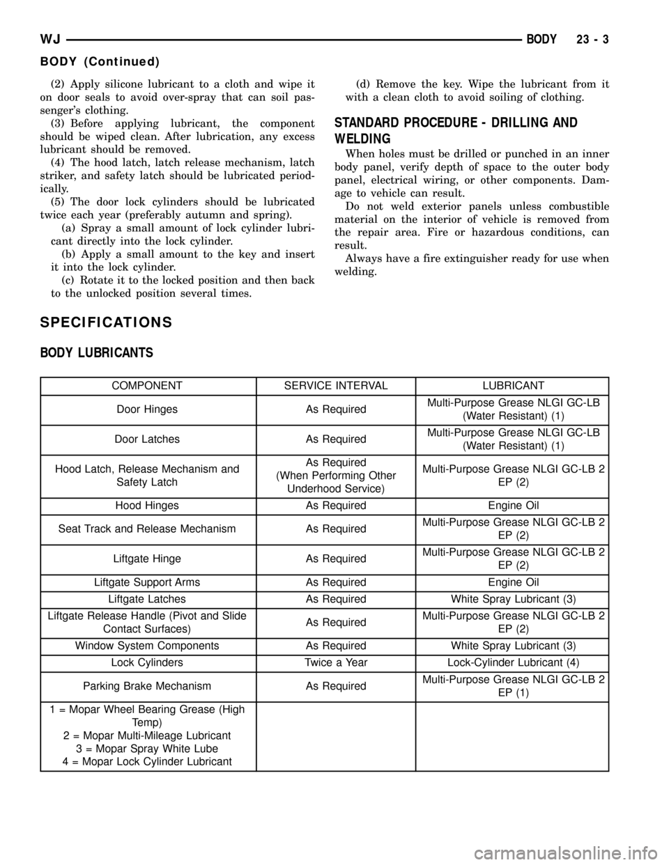
BODY LUBRICANTS
COMPONENT SERVICE INTERVAL LUBRICANT
Door Hinges As RequiredMulti-Purpose Grease NLGI GC-LB
(Water Resistant) (1)
Door Latches As RequiredMulti-Purpose Grease NLGI GC-LB
(Water Resistant) (1)
Hood Latch, Release Mechanism and
Safety LatchAs Required
(When Performing Other
Underhood Service)Multi-Purpose Grease NLGI GC-LB 2
EP (2)
Hood Hinges As Required Engine Oil
Seat Track and Release Mechanism As RequiredMulti-Purpose Grease NLGI GC-LB 2
EP (2)
Liftgate Hinge As RequiredMulti-Purpose Grease NLGI GC-LB 2
EP (2)
Liftgate Support Arms As Required Engine Oil
Liftgate Latches As Required White Spray Lubricant (3)
Liftgate Release Handle (Pivot and Slide
Contact Surfaces)As RequiredMulti-Purpose Grease NLGI GC-LB 2
EP (2)
Window System Components As Required White Spray Lubricant (3)
Lock Cylinders Twice a Year Lock-Cylinder Lubricant (4)
Parking Brake Mechanism As RequiredMulti-Purpose Grease NLGI GC-LB 2
EP (1)
1 = Mopar Wheel Bearing Grease (High
Temp)
2 = Mopar Multi-Mileage Lubricant
3 = Mopar Spray White Lube
4 = Mopar Lock Cylinder Lubricant
WJBODY 23 - 3
BODY (Continued)
Page 1884 of 2199

DOOR - FRONT
TABLE OF CONTENTS
page page
CHECK STRAP
REMOVAL.............................11
INSTALLATION.........................11
DOOR
REMOVAL.............................12
INSTALLATION.........................12
ADJUSTMENTS
DOOR ADJUSTMENT..................12
DOOR GLASS
REMOVAL.............................12
INSTALLATION.........................12
EXTERIOR HANDLE
REMOVAL.............................13
INSTALLATION.........................13
GLASS RUN CHANNEL
REMOVAL.............................13
INSTALLATION.........................14
HINGE
REMOVAL.............................14
INSTALLATION.........................15
INSIDE HANDLE ACTUATOR
REMOVAL.............................15INSTALLATION.........................15
LATCH
REMOVAL.............................15
INSTALLATION.........................15
ADJUSTMENTS
DOOR LATCH........................16
LATCH STRIKER
REMOVAL.............................16
INSTALLATION.........................16
LOCK CYLINDER
REMOVAL.............................16
INSTALLATION.........................17
TRIM PANEL
REMOVAL.............................17
INSTALLATION.........................17
WATERDAM
REMOVAL.............................17
INSTALLATION.........................17
WINDOW REGULATOR
REMOVAL.............................18
INSTALLATION.........................18
CHECK STRAP
REMOVAL
(1) Remove the waterdam, refer to (Refer to 23 -
BODY/DOOR - FRONT/WATERDAM - REMOVAL).
(2) Remove speaker.
(3) Remove screws attaching door check to A-pillar.
(4) Remove nuts attaching door check to door (Fig.
1).
(5) Remove door check through speaker location
hole.
INSTALLATION
(1) Position door check on door through speaker
location hole (Fig. 1).
(2) Install nuts attaching door check to door.
(3) Install screws attaching door check to A-pillar.
(4) Install speaker.
(5) Install the waterdam, refer to (Refer to 23 -
BODY/DOOR - FRONT/WATERDAM - INSTALLA-
TION).
Fig. 1 Door Check
1 - DOOR CHECK
2 - FRONT DOOR
WJDOOR - FRONT 23 - 11
Page 1886 of 2199
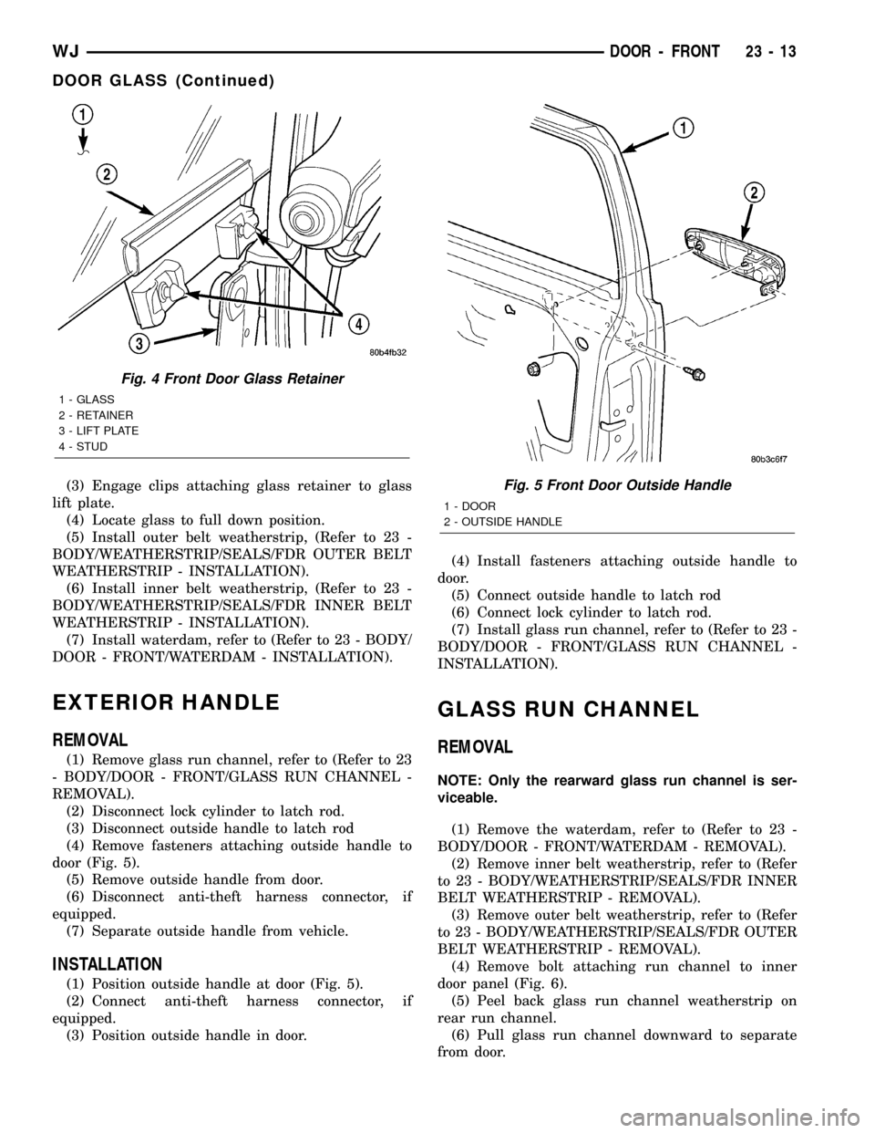
(3) Engage clips attaching glass retainer to glass
lift plate.
(4) Locate glass to full down position.
(5) Install outer belt weatherstrip, (Refer to 23 -
BODY/WEATHERSTRIP/SEALS/FDR OUTER BELT
WEATHERSTRIP - INSTALLATION).
(6) Install inner belt weatherstrip, (Refer to 23 -
BODY/WEATHERSTRIP/SEALS/FDR INNER BELT
WEATHERSTRIP - INSTALLATION).
(7) Install waterdam, refer to (Refer to 23 - BODY/
DOOR - FRONT/WATERDAM - INSTALLATION).
EXTERIOR HANDLE
REMOVAL
(1) Remove glass run channel, refer to (Refer to 23
- BODY/DOOR - FRONT/GLASS RUN CHANNEL -
REMOVAL).
(2) Disconnect lock cylinder to latch rod.
(3) Disconnect outside handle to latch rod
(4) Remove fasteners attaching outside handle to
door (Fig. 5).
(5) Remove outside handle from door.
(6) Disconnect anti-theft harness connector, if
equipped.
(7) Separate outside handle from vehicle.
INSTALLATION
(1) Position outside handle at door (Fig. 5).
(2) Connect anti-theft harness connector, if
equipped.
(3) Position outside handle in door.(4) Install fasteners attaching outside handle to
door.
(5) Connect outside handle to latch rod
(6) Connect lock cylinder to latch rod.
(7) Install glass run channel, refer to (Refer to 23 -
BODY/DOOR - FRONT/GLASS RUN CHANNEL -
INSTALLATION).
GLASS RUN CHANNEL
REMOVAL
NOTE: Only the rearward glass run channel is ser-
viceable.
(1) Remove the waterdam, refer to (Refer to 23 -
BODY/DOOR - FRONT/WATERDAM - REMOVAL).
(2) Remove inner belt weatherstrip, refer to (Refer
to 23 - BODY/WEATHERSTRIP/SEALS/FDR INNER
BELT WEATHERSTRIP - REMOVAL).
(3) Remove outer belt weatherstrip, refer to (Refer
to 23 - BODY/WEATHERSTRIP/SEALS/FDR OUTER
BELT WEATHERSTRIP - REMOVAL).
(4) Remove bolt attaching run channel to inner
door panel (Fig. 6).
(5) Peel back glass run channel weatherstrip on
rear run channel.
(6) Pull glass run channel downward to separate
from door.
Fig. 4 Front Door Glass Retainer
1 - GLASS
2 - RETAINER
3 - LIFT PLATE
4 - STUD
Fig. 5 Front Door Outside Handle
1 - DOOR
2 - OUTSIDE HANDLE
WJDOOR - FRONT 23 - 13
DOOR GLASS (Continued)
Page 1888 of 2199
INSTALLATION
(1) Position hinge on ªAº pillar. (Use 3MtFast and
Firm or equivalent on the hinge to body mating sur-
face as a sealant.)
(2) Install hinge to body bolts, but do not tighten.
(3) Align the hinge to the reference marks and
torque the bolts to 35N´m (26 ft. lbs.).
(4) Install the door on the hinge and align with the
reference marks.
(5) Tighten the door to hinge fasteners.
(6) For adjustment see door adjustment procedure.
INSIDE HANDLE ACTUATOR
REMOVAL
(1) Remove door trim panel, refer to (Refer to 23 -
BODY/DOOR - FRONT/TRIM PANEL - REMOVAL).
(2) Disconnect latch and lock rods from inside han-
dle actuator.
(3) Remove screws attaching inside handle actua-
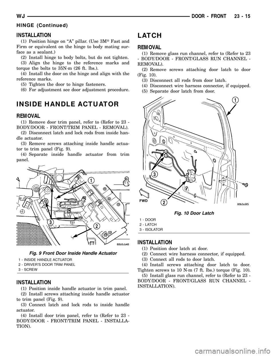
tor to trim panel (Fig. 9).
(4) Separate inside handle actuator from trim
panel.
INSTALLATION
(1) Position inside handle actuator in trim panel.
(2) Install screws attaching inside handle actuator
to trim panel (Fig. 9).
(3) Connect latch and lock rods to inside handle
actuator.
(4) Install door trim panel, refer to (Refer to 23 -
BODY/DOOR - FRONT/TRIM PANEL - INSTALLA-
TION).
LATCH
REMOVAL
(1) Remove glass run channel, refer to (Refer to 23
- BODY/DOOR - FRONT/GLASS RUN CHANNEL -
REMOVAL).
(2) Remove screws attaching door latch to door
(Fig. 10).
(3) Disconnect all rods from door latch.
(4) Disconnect wire harness connector, if equipped.
(5) Separate door latch from door.
INSTALLATION
(1) Position door latch at door.
(2) Connect wire harness connector, if equipped.
(3) Connect all rods to door latch.
(4) Install screws attaching door latch to door.
Tighten screws to 10 N´m (7 ft. lbs.) torque (Fig. 10).
(5) Install glass run channel, refer to (Refer to 23 -
BODY/DOOR - FRONT/GLASS RUN CHANNEL -
INSTALLATION).
Fig. 9 Front Door Inside Handle Actuator
1 - INSIDE HANDLE ACTUATOR
2 - DRIVER'S DOOR TRIM PANEL
3 - SCREW
Fig. 10 Door Latch
1 - DOOR
2-LATCH
3 - ISOLATOR
WJDOOR - FRONT 23 - 15
HINGE (Continued)
Page 1889 of 2199
ADJUSTMENTS
DOOR LATCH
DOOR LATCH ADJUSTMENT
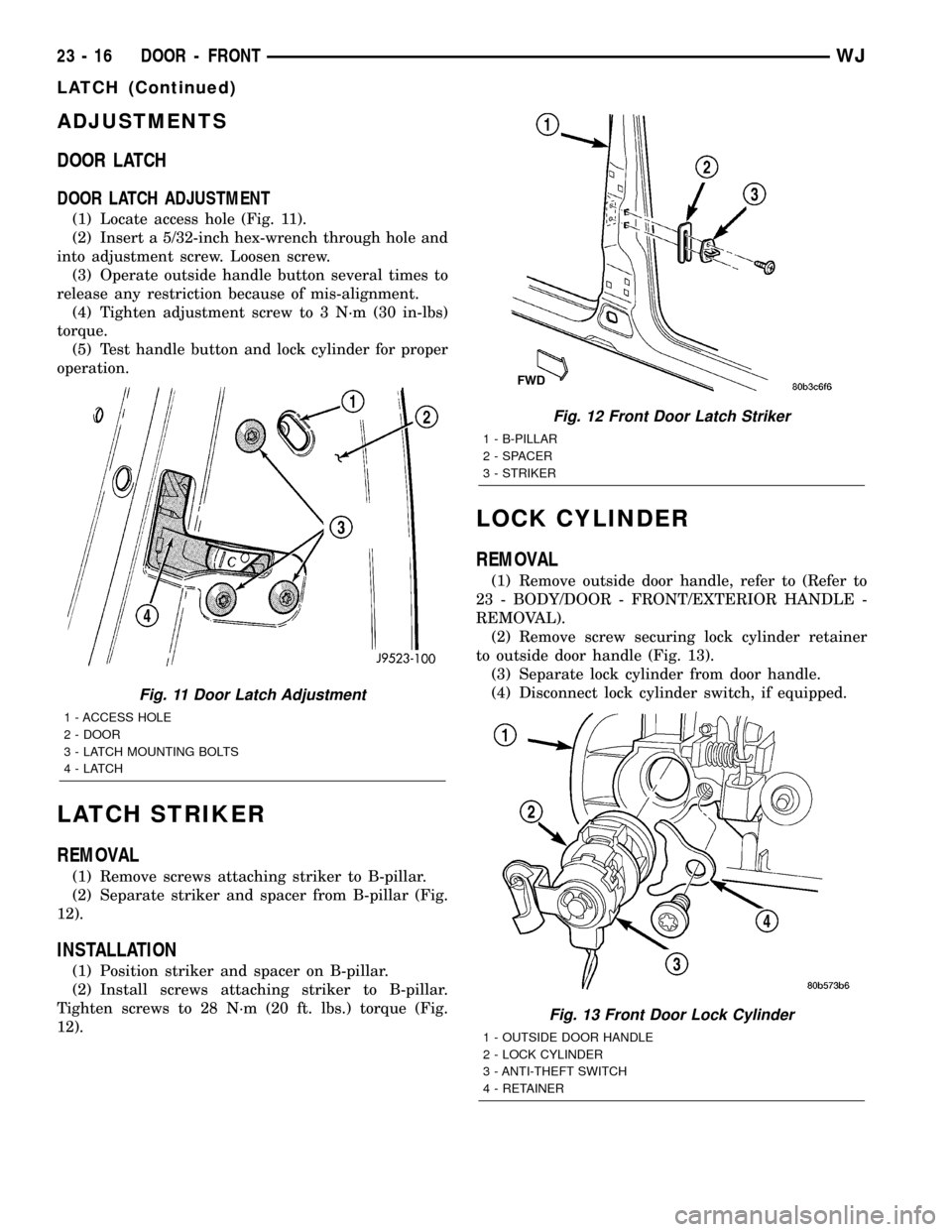
(1) Locate access hole (Fig. 11).
(2) Insert a 5/32-inch hex-wrench through hole and
into adjustment screw. Loosen screw.
(3) Operate outside handle button several times to
release any restriction because of mis-alignment.
(4) Tighten adjustment screw to 3 N´m (30 in-lbs)
torque.
(5) Test handle button and lock cylinder for proper
operation.
LATCH STRIKER
REMOVAL
(1) Remove screws attaching striker to B-pillar.
(2) Separate striker and spacer from B-pillar (Fig.
12).
INSTALLATION
(1) Position striker and spacer on B-pillar.
(2) Install screws attaching striker to B-pillar.
Tighten screws to 28 N´m (20 ft. lbs.) torque (Fig.
12).
LOCK CYLINDER
REMOVAL
(1) Remove outside door handle, refer to (Refer to
23 - BODY/DOOR - FRONT/EXTERIOR HANDLE -
REMOVAL).
(2) Remove screw securing lock cylinder retainer
to outside door handle (Fig. 13).
(3) Separate lock cylinder from door handle.
(4) Disconnect lock cylinder switch, if equipped.
Fig. 11 Door Latch Adjustment
1 - ACCESS HOLE
2 - DOOR
3 - LATCH MOUNTING BOLTS
4-LATCH
Fig. 12 Front Door Latch Striker
1 - B-PILLAR
2 - SPACER
3 - STRIKER
Fig. 13 Front Door Lock Cylinder
1 - OUTSIDE DOOR HANDLE
2 - LOCK CYLINDER
3 - ANTI-THEFT SWITCH
4 - RETAINER
23 - 16 DOOR - FRONTWJ
LATCH (Continued)