door handle JEEP GRAND CHEROKEE 2002 WJ / 2.G Workshop Manual
[x] Cancel search | Manufacturer: JEEP, Model Year: 2002, Model line: GRAND CHEROKEE, Model: JEEP GRAND CHEROKEE 2002 WJ / 2.GPages: 2199, PDF Size: 76.01 MB
Page 91 of 2199
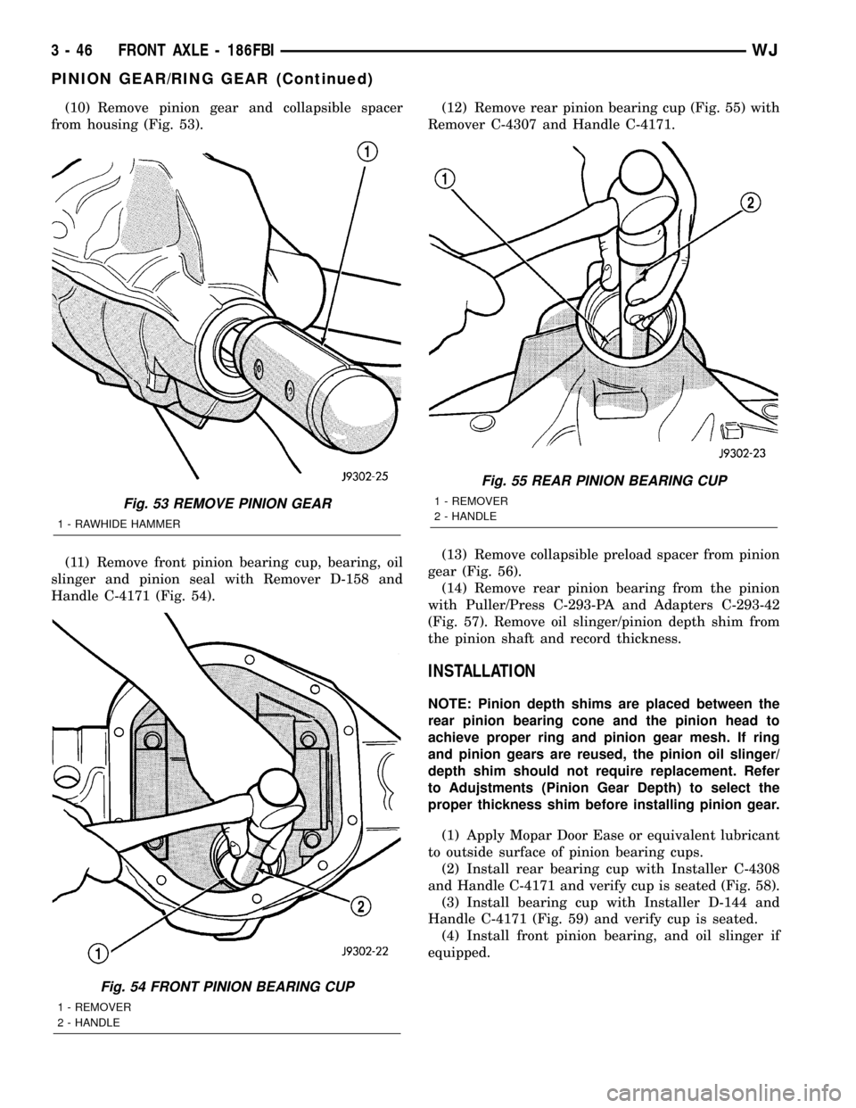
(10) Remove pinion gear and collapsible spacer
from housing (Fig. 53).
(11) Remove front pinion bearing cup, bearing, oil
slinger and pinion seal with Remover D-158 and
Handle C-4171 (Fig. 54).(12) Remove rear pinion bearing cup (Fig. 55) with
Remover C-4307 and Handle C-4171.
(13) Remove collapsible preload spacer from pinion
gear (Fig. 56).
(14) Remove rear pinion bearing from the pinion
with Puller/Press C-293-PA and Adapters C-293-42
(Fig. 57). Remove oil slinger/pinion depth shim from
the pinion shaft and record thickness.
INSTALLATION
NOTE: Pinion depth shims are placed between the
rear pinion bearing cone and the pinion head to
achieve proper ring and pinion gear mesh. If ring
and pinion gears are reused, the pinion oil slinger/
depth shim should not require replacement. Refer
to Adujstments (Pinion Gear Depth) to select the
proper thickness shim before installing pinion gear.
(1) Apply Mopar Door Ease or equivalent lubricant
to outside surface of pinion bearing cups.
(2) Install rear bearing cup with Installer C-4308
and Handle C-4171 and verify cup is seated (Fig. 58).
(3) Install bearing cup with Installer D-144 and
Handle C-4171 (Fig. 59) and verify cup is seated.
(4) Install front pinion bearing, and oil slinger if
equipped.
Fig. 53 REMOVE PINION GEAR
1 - RAWHIDE HAMMER
Fig. 54 FRONT PINION BEARING CUP
1 - REMOVER
2 - HANDLE
Fig. 55 REAR PINION BEARING CUP
1 - REMOVER
2 - HANDLE
3 - 46 FRONT AXLE - 186FBIWJ
PINION GEAR/RING GEAR (Continued)
Page 132 of 2199
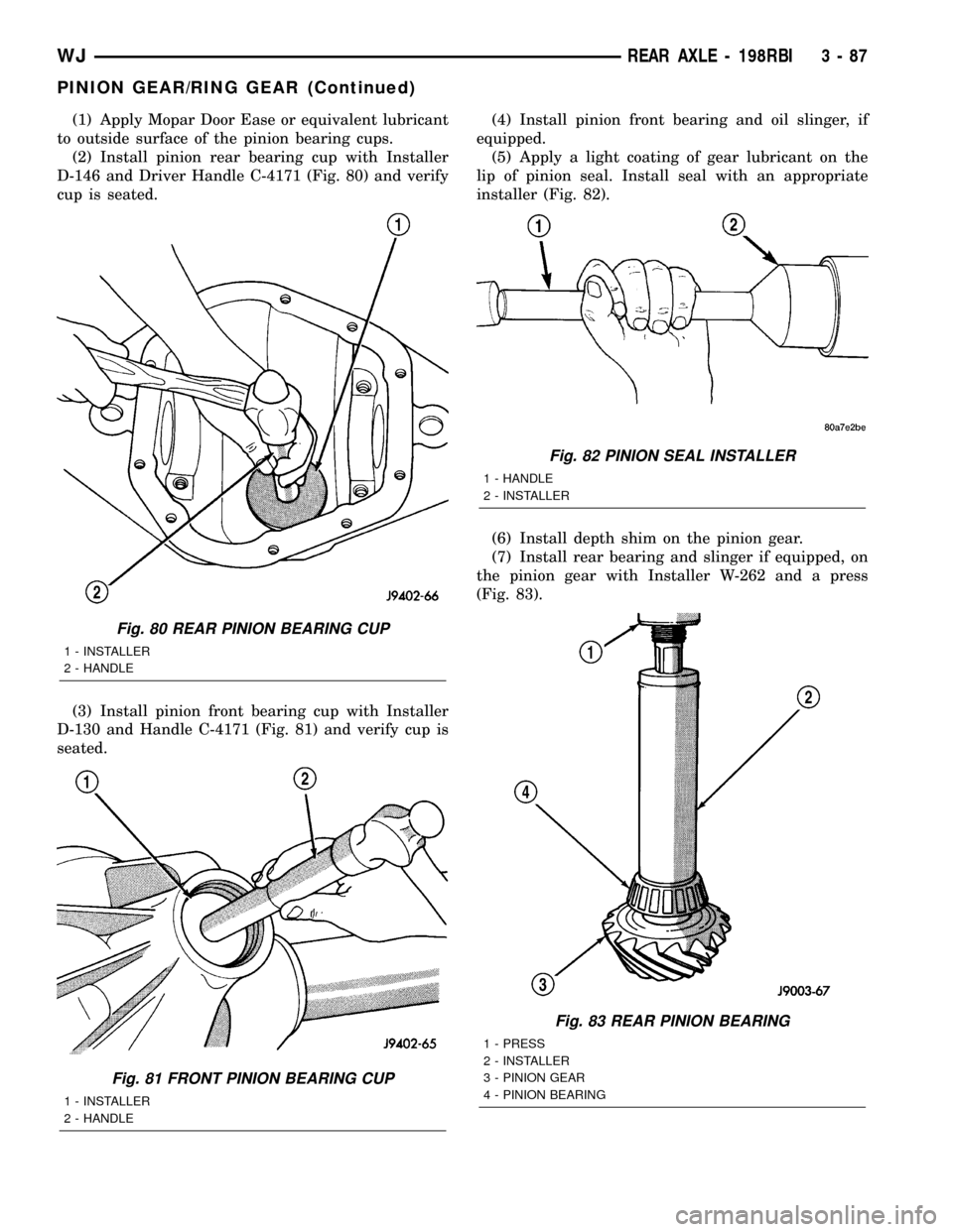
(1) Apply Mopar Door Ease or equivalent lubricant
to outside surface of the pinion bearing cups.
(2) Install pinion rear bearing cup with Installer
D-146 and Driver Handle C-4171 (Fig. 80) and verify
cup is seated.
(3) Install pinion front bearing cup with Installer
D-130 and Handle C-4171 (Fig. 81) and verify cup is
seated.(4) Install pinion front bearing and oil slinger, if
equipped.
(5) Apply a light coating of gear lubricant on the
lip of pinion seal. Install seal with an appropriate
installer (Fig. 82).
(6) Install depth shim on the pinion gear.
(7) Install rear bearing and slinger if equipped, on
the pinion gear with Installer W-262 and a press
(Fig. 83).
Fig. 80 REAR PINION BEARING CUP
1 - INSTALLER
2 - HANDLE
Fig. 81 FRONT PINION BEARING CUP
1 - INSTALLER
2 - HANDLE
Fig. 82 PINION SEAL INSTALLER
1 - HANDLE
2 - INSTALLER
Fig. 83 REAR PINION BEARING
1 - PRESS
2 - INSTALLER
3 - PINION GEAR
4 - PINION BEARING
WJREAR AXLE - 198RBI 3 - 87
PINION GEAR/RING GEAR (Continued)
Page 172 of 2199
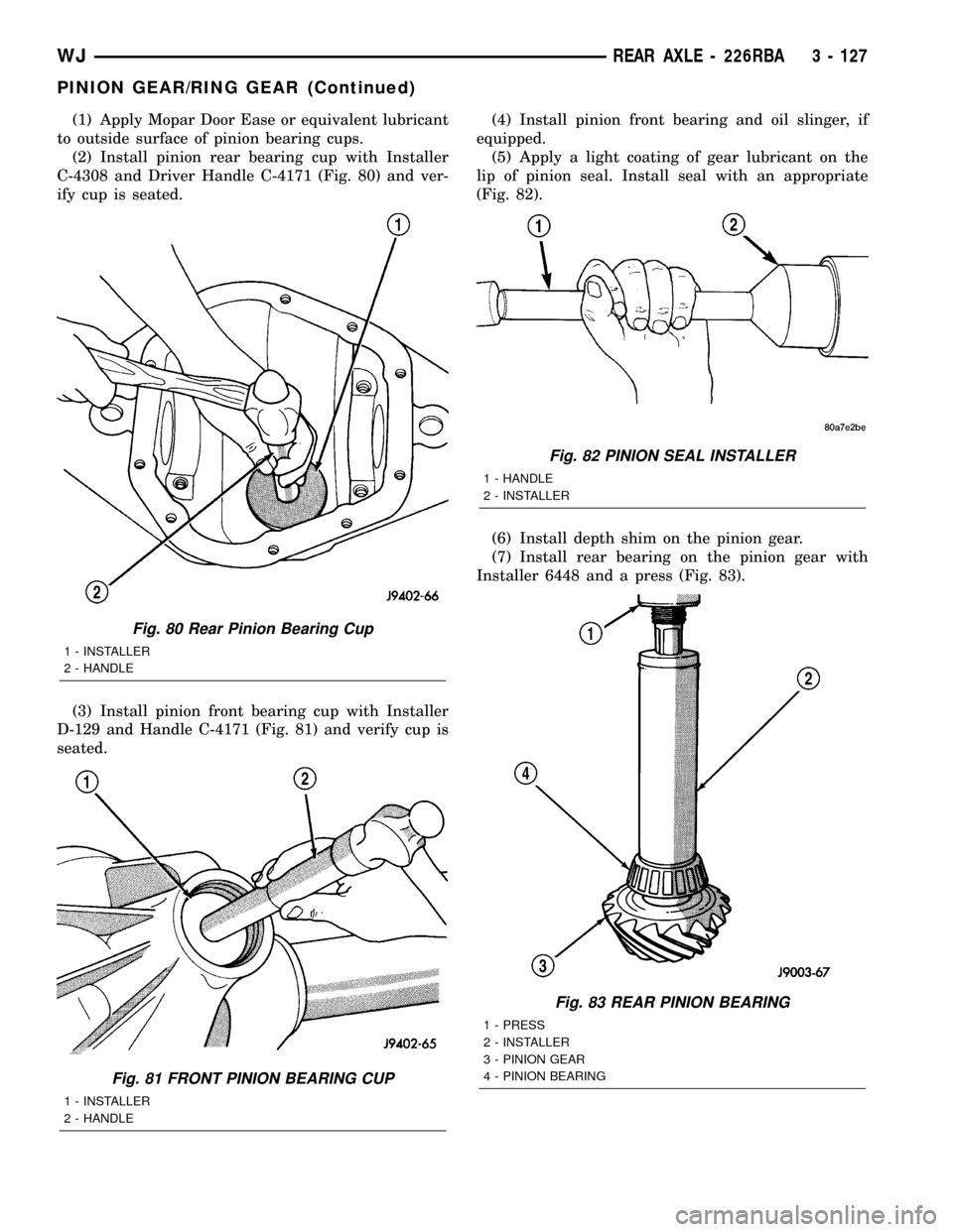
(1) Apply Mopar Door Ease or equivalent lubricant
to outside surface of pinion bearing cups.
(2) Install pinion rear bearing cup with Installer
C-4308 and Driver Handle C-4171 (Fig. 80) and ver-
ify cup is seated.
(3) Install pinion front bearing cup with Installer
D-129 and Handle C-4171 (Fig. 81) and verify cup is
seated.(4) Install pinion front bearing and oil slinger, if
equipped.
(5) Apply a light coating of gear lubricant on the
lip of pinion seal. Install seal with an appropriate
(Fig. 82).
(6) Install depth shim on the pinion gear.
(7) Install rear bearing on the pinion gear with
Installer 6448 and a press (Fig. 83).
Fig. 80 Rear Pinion Bearing Cup
1 - INSTALLER
2 - HANDLE
Fig. 81 FRONT PINION BEARING CUP
1 - INSTALLER
2 - HANDLE
Fig. 82 PINION SEAL INSTALLER
1 - HANDLE
2 - INSTALLER
Fig. 83 REAR PINION BEARING
1 - PRESS
2 - INSTALLER
3 - PINION GEAR
4 - PINION BEARING
WJREAR AXLE - 226RBA 3 - 127
PINION GEAR/RING GEAR (Continued)
Page 479 of 2199
LAMPS/LIGHTING - INTERIOR
TABLE OF CONTENTS
page page
LAMPS/LIGHTING - INTERIOR
SPECIFICATIONS
...................................28
COURTESY LAMP
REMOVAL
REMOVAL - BULB.....................29
REMOVAL - LAMP.....................29
INSTALLATION
INSTALLATION - BULB.................29
INSTALLATION - LAMP.................29
DOME LAMP
REMOVAL
REMOVAL - BULB.....................29
REMOVAL - LAMP.....................29
INSTALLATION
INSTALLATION - BULB.................29
INSTALLATION - LAMP.................29
DOOR AJAR SWITCH
DESCRIPTION
DESCRIPTION - DOOR AJAR SWITCH.....29
DESCRIPTION - FLIP UP GLASS AJAR
SWITCH............................29DESCRIPTION - LIFTGATE AJAR SWITCH . . 30
OPERATION
OPERATION - DOOR AJAR SWITCH.......30
OPERATION - FLIP UP GLASS AJAR
SWITCH............................30
OPERATION - LIFTGATE AJAR SWITCH....30
DIAGNOSIS AND TESTING - DOOR AJAR
SWITCH............................30
GLOVE BOX LAMP/SWITCH
REMOVAL.............................31
INSTALLATION.........................31
READING LAMP
DESCRIPTION.........................32
OPERATION...........................32
REMOVAL.............................32
INSTALLATION.........................32
TRANS RANGE INDICATOR ILLUMINATION
DESCRIPTION.........................32
VANITY LAMP
REMOVAL.............................32
INSTALLATION.........................32
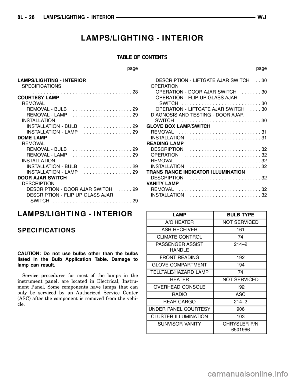
LAMPS/LIGHTING - INTERIOR
SPECIFICATIONS
CAUTION: Do not use bulbs other than the bulbs
listed in the Bulb Application Table. Damage to
lamp can result.
Service procedures for most of the lamps in the
instrument panel, are located in Electrical, Instru-
ment Panel. Some components have lamps that can
only be serviced by an Authorized Service Center
(ASC) after the component is removed from the vehi-
cle.
LAMP BULB TYPE
A/C HEATER NOT SERVICED
ASH RECEIVER 161
CLIMATE CONTROL 74
PASSENGER ASSIST
HANDLE214±2
FRONT READING 192
GLOVE COMPARTMENT 194
TELLTALE/HAZARD LAMP 74
HEATER NOT SERVICED
OVERHEAD CONSOLE 192
RADIO ASC
REAR CARGO 214±2
UNDER PANEL COURTESY 906
CLUSTER ILLUMINATION 103
SUNVISOR VANITY CHRYSLER P/N
6501966
8L - 28 LAMPS/LIGHTING - INTERIORWJ
Page 480 of 2199

COURTESY LAMP
REMOVAL
REMOVAL - BULB
(1) Remove the door trim panel. (Refer to 23 -
BODY/DOOR - FRONT/TRIM PANEL - REMOVAL)
for the service procedures.
(2) Remove the bulb socket from the lamp.
(3) Remove the bulb from the socket.
REMOVAL - LAMP
(1) Remove door trim panel. (Refer to 23 - BODY/
DOOR - FRONT/TRIM PANEL - REMOVAL) for the
procedures.
(2) Disengage the electrical connectors.
(3) Depress the locking tabs and remove the lamp
module.
(4) Remove the bulb socket.
INSTALLATION
INSTALLATION - BULB
(1) Install the bulb in the socket.
(2) Install the bulb socket in the lamp.
(3) Install the door trim panel.
INSTALLATION - LAMP
(1) Install the bulb socket into the lamp module.
(2) Align the lamp module with the door trim
panel.
(3) Snap the lamp module into place.
(4) Install the door panel.
DOME LAMP
REMOVAL
REMOVAL - BULB
(1) Rotate the the grab handle down.
(2) Remove the screws retaining the grab handle/
dome lens.
(3) Remove the grab handle/lens from the module.
(4) Remove the bulb from the lamp terminals.
REMOVAL - LAMP
It will be necessary to partially remove the head-
liner to remove the bulb socket.
(1) Remove the screws holding the grab handle/
lens assembly to the headliner and roof panel.(2) Lower the headliner as needed. (Refer to 23 -
BODY/INTERIOR/HEADLINER - REMOVAL) for the
service procedure.
(3) Separate the lamp socket from the headliner
and roof panel.
(4) Disconnect the wire connector.
INSTALLATION
INSTALLATION - BULB
(1) Insert the bulb into the lamp terminals.
(2) Position the grab handle/lens on the lamp mod-
ule.
(3) Install the screws retaining the grab handle/
lens to the lamp module.
INSTALLATION - LAMP
(1) Position the lamp socket on the headliner and
roof panel.
(2) Connect the wire harness.
(3) Install the headliner.
(4) Position the grab handle/lens on the lamp mod-
ule.
(5) Install the screws retaining the grab handle/
lens into the lamp socket.
DOOR AJAR SWITCH
DESCRIPTION
DESCRIPTION - DOOR AJAR SWITCH
The door ajar switches are integral to the door
latch mechnicism. The front door ajar switches are
actuated by the front door latch mechanisms, and are
hard wired between a body ground and the Driver
Door Module (DDM) or the Passenger Door Module
(PDM). The rear door ajar switches are actuated by
the rear door latch mechanisms, and are hard wired
between a body ground and the Body Control Module
(BCM) through the rear door and body wire har-
nesses.
The door ajar switches cannot be adjusted or
repaired and, if faulty or damaged, the door latch
unit must be replaced. (Refer to 23 - BODY/DOOR -
FRONT/LATCH - REMOVAL) or (Refer to 23 -
BODY/DOORS - REAR/LATCH - REMOVAL) for the
service procedures. For complete circuit diagrams,
refer to the appropriate wiring information.
DESCRIPTION - FLIP UP GLASS AJAR SWITCH
The liftgate flip-up glass ajar switch is integral to
the liftgate flip-up glass latch mechnicism. The lift-
gate flip-up glass ajar switch is actuated by the lift-
gate flip-up glass latch mechanism, and is hard
WJLAMPS/LIGHTING - INTERIOR 8L - 29
Page 599 of 2199
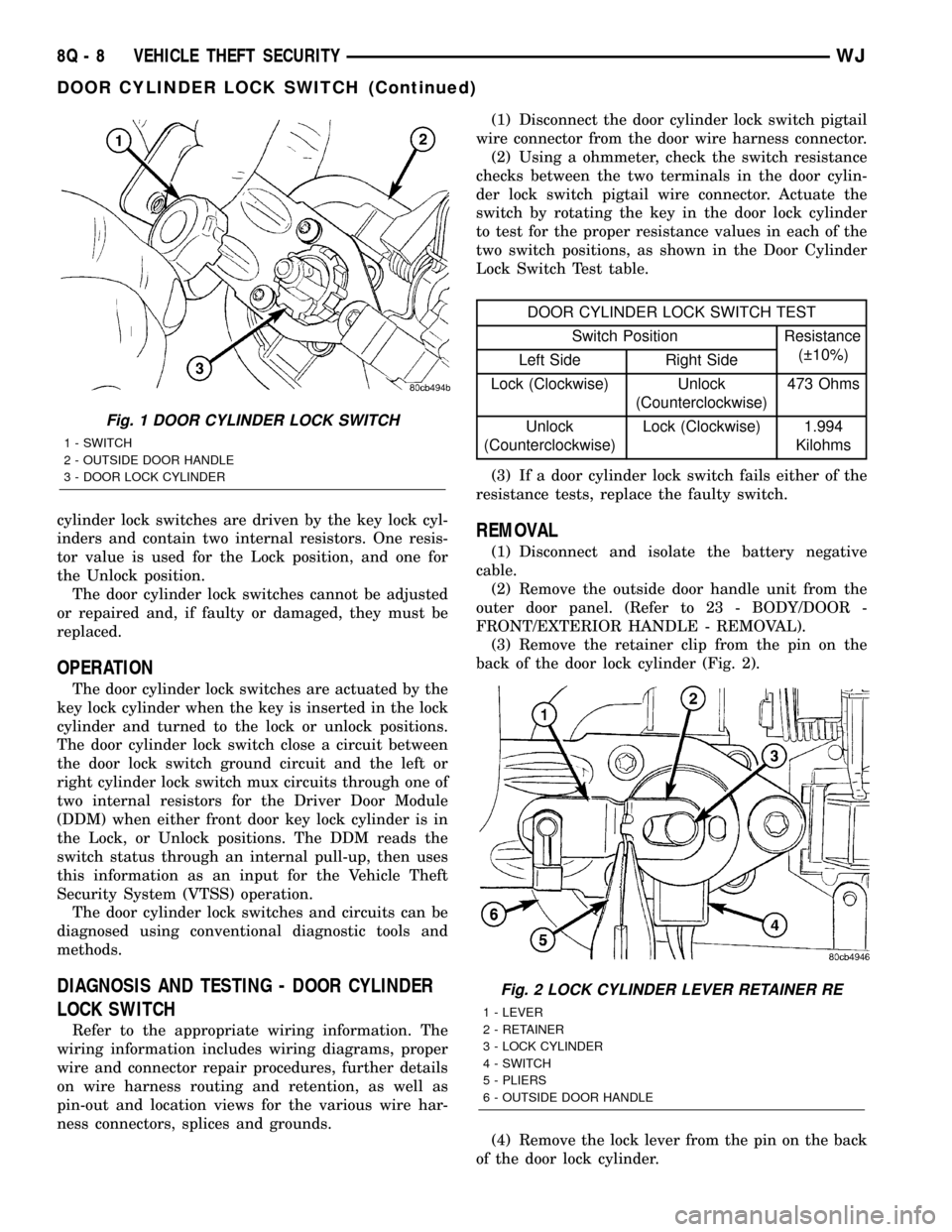
cylinder lock switches are driven by the key lock cyl-
inders and contain two internal resistors. One resis-
tor value is used for the Lock position, and one for
the Unlock position.
The door cylinder lock switches cannot be adjusted
or repaired and, if faulty or damaged, they must be
replaced.
OPERATION
The door cylinder lock switches are actuated by the
key lock cylinder when the key is inserted in the lock
cylinder and turned to the lock or unlock positions.
The door cylinder lock switch close a circuit between
the door lock switch ground circuit and the left or
right cylinder lock switch mux circuits through one of
two internal resistors for the Driver Door Module
(DDM) when either front door key lock cylinder is in
the Lock, or Unlock positions. The DDM reads the
switch status through an internal pull-up, then uses
this information as an input for the Vehicle Theft
Security System (VTSS) operation.
The door cylinder lock switches and circuits can be
diagnosed using conventional diagnostic tools and
methods.
DIAGNOSIS AND TESTING - DOOR CYLINDER
LOCK SWITCH
Refer to the appropriate wiring information. The
wiring information includes wiring diagrams, proper
wire and connector repair procedures, further details
on wire harness routing and retention, as well as
pin-out and location views for the various wire har-
ness connectors, splices and grounds.(1) Disconnect the door cylinder lock switch pigtail
wire connector from the door wire harness connector.
(2) Using a ohmmeter, check the switch resistance
checks between the two terminals in the door cylin-
der lock switch pigtail wire connector. Actuate the
switch by rotating the key in the door lock cylinder
to test for the proper resistance values in each of the
two switch positions, as shown in the Door Cylinder
Lock Switch Test table.
DOOR CYLINDER LOCK SWITCH TEST
Switch Position Resistance
( 10%)
Left Side Right Side
Lock (Clockwise) Unlock
(Counterclockwise)473 Ohms
Unlock
(Counterclockwise)Lock (Clockwise) 1.994
Kilohms
(3) If a door cylinder lock switch fails either of the
resistance tests, replace the faulty switch.
REMOVAL
(1) Disconnect and isolate the battery negative
cable.
(2) Remove the outside door handle unit from the
outer door panel. (Refer to 23 - BODY/DOOR -
FRONT/EXTERIOR HANDLE - REMOVAL).
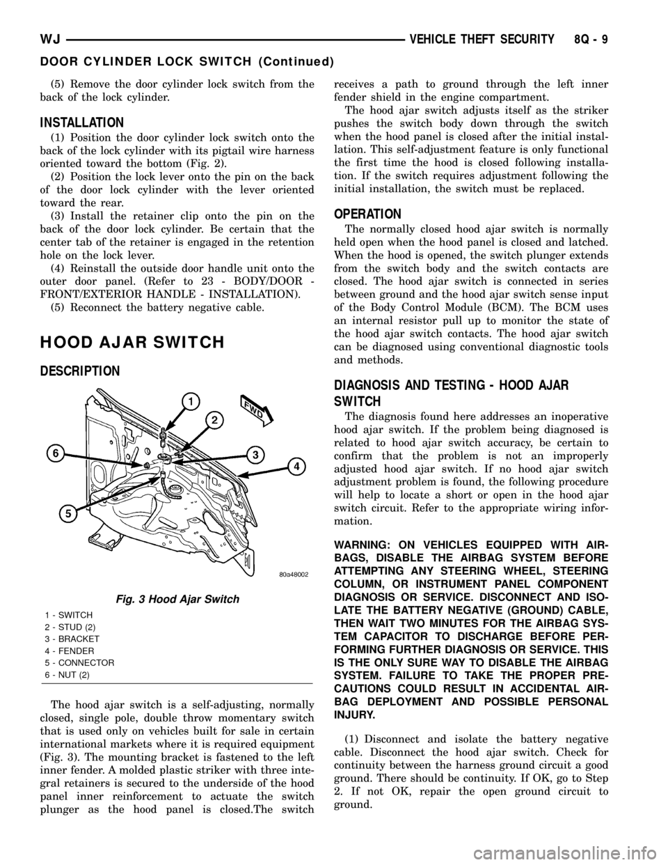
(3) Remove the retainer clip from the pin on the
back of the door lock cylinder (Fig. 2).
(4) Remove the lock lever from the pin on the back
of the door lock cylinder.
Fig. 1 DOOR CYLINDER LOCK SWITCH
1 - SWITCH
2 - OUTSIDE DOOR HANDLE
3 - DOOR LOCK CYLINDER
Fig. 2 LOCK CYLINDER LEVER RETAINER RE
1 - LEVER
2 - RETAINER
3 - LOCK CYLINDER
4 - SWITCH
5 - PLIERS
6 - OUTSIDE DOOR HANDLE
8Q - 8 VEHICLE THEFT SECURITYWJ
DOOR CYLINDER LOCK SWITCH (Continued)
Page 600 of 2199
(5) Remove the door cylinder lock switch from the
back of the lock cylinder.
INSTALLATION
(1) Position the door cylinder lock switch onto the
back of the lock cylinder with its pigtail wire harness
oriented toward the bottom (Fig. 2).
(2) Position the lock lever onto the pin on the back
of the door lock cylinder with the lever oriented
toward the rear.
(3) Install the retainer clip onto the pin on the
back of the door lock cylinder. Be certain that the
center tab of the retainer is engaged in the retention
hole on the lock lever.
(4) Reinstall the outside door handle unit onto the
outer door panel. (Refer to 23 - BODY/DOOR -
FRONT/EXTERIOR HANDLE - INSTALLATION).
(5) Reconnect the battery negative cable.
HOOD AJAR SWITCH
DESCRIPTION
The hood ajar switch is a self-adjusting, normally
closed, single pole, double throw momentary switch
that is used only on vehicles built for sale in certain
international markets where it is required equipment
(Fig. 3). The mounting bracket is fastened to the left
inner fender. A molded plastic striker with three inte-
gral retainers is secured to the underside of the hood
panel inner reinforcement to actuate the switch
plunger as the hood panel is closed.The switchreceives a path to ground through the left inner
fender shield in the engine compartment.
The hood ajar switch adjusts itself as the striker
pushes the switch body down through the switch
when the hood panel is closed after the initial instal-
lation. This self-adjustment feature is only functional
the first time the hood is closed following installa-
tion. If the switch requires adjustment following the
initial installation, the switch must be replaced.
OPERATION
The normally closed hood ajar switch is normally
held open when the hood panel is closed and latched.
When the hood is opened, the switch plunger extends
from the switch body and the switch contacts are
closed. The hood ajar switch is connected in series
between ground and the hood ajar switch sense input
of the Body Control Module (BCM). The BCM uses
an internal resistor pull up to monitor the state of
the hood ajar switch contacts. The hood ajar switch
can be diagnosed using conventional diagnostic tools
and methods.
DIAGNOSIS AND TESTING - HOOD AJAR
SWITCH
The diagnosis found here addresses an inoperative
hood ajar switch. If the problem being diagnosed is
related to hood ajar switch accuracy, be certain to
confirm that the problem is not an improperly
adjusted hood ajar switch. If no hood ajar switch
adjustment problem is found, the following procedure
will help to locate a short or open in the hood ajar
switch circuit. Refer to the appropriate wiring infor-
mation.
WARNING: ON VEHICLES EQUIPPED WITH AIR-
BAGS, DISABLE THE AIRBAG SYSTEM BEFORE
ATTEMPTING ANY STEERING WHEEL, STEERING
COLUMN, OR INSTRUMENT PANEL COMPONENT
DIAGNOSIS OR SERVICE. DISCONNECT AND ISO-
LATE THE BATTERY NEGATIVE (GROUND) CABLE,
THEN WAIT TWO MINUTES FOR THE AIRBAG SYS-
TEM CAPACITOR TO DISCHARGE BEFORE PER-
FORMING FURTHER DIAGNOSIS OR SERVICE. THIS
IS THE ONLY SURE WAY TO DISABLE THE AIRBAG
SYSTEM. FAILURE TO TAKE THE PROPER PRE-
CAUTIONS COULD RESULT IN ACCIDENTAL AIR-
BAG DEPLOYMENT AND POSSIBLE PERSONAL
INJURY.
(1) Disconnect and isolate the battery negative
cable. Disconnect the hood ajar switch. Check for
continuity between the harness ground circuit a good
ground. There should be continuity. If OK, go to Step
2. If not OK, repair the open ground circuit to
ground.
Fig. 3 Hood Ajar Switch
1 - SWITCH
2 - STUD (2)
3 - BRACKET
4 - FENDER
5 - CONNECTOR
6 - NUT (2)
WJVEHICLE THEFT SECURITY 8Q - 9
DOOR CYLINDER LOCK SWITCH (Continued)
Page 706 of 2199
8W-12 JUNCTION BLOCK
Component PageA/C Compressor Clutch Relay................8W-12-18
Accessory Delay Relay.....................8W-12-25
Adjustable Pedals Module..................8W-12-11
Airbag Control Module....................8W-12-25
Auto Shut Down Relay....................8W-12-18
Automatic Day/Night Mirror.................8W-12-23
Automatic Headlamp Light Sensor/VTSS LED......8W-12-15
Automatic Zone Control Module..........8W-12-15, 17, 22
Back-Up Lamp Relay.....................8W-12-22
Body Control Module . . . 8W-12-10, 12, 13, 15, 17, 20, 23, 24, 25,
26, 27, 28, 29, 30, 31, 35, 36
Brake Lamp Switch......................8W-12-24
Cargo Lamp......................8W-12-16, 24, 27
Cigar Lighter..........................8W-12-17
Cigar Lighter Relay....................8W-12-17, 26
Circuit Breaker No. 1...................8W-12-28, 29
Circuit Breaker No. 2......................8W-12-9
Clockspring...........................8W-12-31
Combination Flasher............8W-12-10, 22, 27, 32, 35
Controller Antilock Brake..................8W-12-21
Data Link Connector.....................8W-12-10
Driver Door Module......................8W-12-34
Driver Heated Seat Switch..................8W-12-22
Driver Lumbar Switch.....................8W-12-9
Driver Power Seat Switch...................8W-12-9
Electric Brake..........................8W-12-21
Engine Control Module....................8W-12-19
Engine Starter Motor Relay.................8W-12-26
EVAP/Purge Solenoid.....................8W-12-18
Fog Lamp Relay........................8W-12-24
Front Power Outlet......................8W-12-11
Front Wiper Motor....................8W-12-28, 29
Fuel Pump Relay........................8W-12-18
Fuse 2..............................8W-12-17
Fuse 3............................8W-12-10, 20
Fuse 4..............................8W-12-10
Fuse 5..............................8W-12-11
Fuse 6............................8W-12-12, 13
Fuse 7..............................8W-12-15
Fuse 8..............................8W-12-16
Fuse 9..............................8W-12-11
Fuse 10..............................8W-12-11
Fuse 11..............................8W-12-17
Fuse 12.......................8W-12-18, 19, 21, 34
Fuse 14..............................8W-12-20
Fuse 15.........................8W-12-11, 15, 20
Fuse 16..............................8W-12-10
Fuse 17..............................8W-12-10
Fuse 18...........................8W-12-21, 34
Fuse 19..............................8W-12-21
Fuse 20..............................8W-12-22
Fuse 21...........................8W-12-18, 19
Fuse 22..............................8W-12-23
Fuse 23..............................8W-12-24
Fuse 24..............................8W-12-24
Fuse 25..............................8W-12-25
Fuse 26..............................8W-12-17
Fuse 27..............................8W-12-36
Fuse 28..............................8W-12-26
Fuse 29..............................8W-12-26
Fuse 30..............................8W-12-26
Fuse 31..............................8W-12-26
Fuse 32..............................8W-12-25
Fuse 33..............................8W-12-25
G200...............................8W-12-35
Glove Box Lamp........................8W-12-16
Headlamp Leveling Switch...............8W-12-12, 13
High Beam Relay........................8W-12-10
Horn Relay...........................8W-12-31
Horn Switch...........................8W-12-31
Instrument Cluster..................8W-12-10, 23, 32
Intrusion Transceiver Module................8W-12-16
Junction Block.........8W-12-2, 3, 9, 10, 11, 12, 13, 15, 16,
17, 18, 19, 20, 21, 22, 23, 24, 25,
26, 27, 28, 29, 30, 31, 32, 34, 35, 36Component PageLeft Courtesy Lamp......................8W-12-16
Left Door Handle Courtesy Lamp.........8W-12-16, 24, 30
Left Fog Lamp.........................8W-12-24
Left Front Park Lamp.....................8W-12-14
Left Front Park/Turn Signal Lamp...........8W-12-14, 33
Left Front Side Marker Lamp..............8W-12-14, 33
Left Front Turn Signal Lamp................8W-12-33
Left Headlamp Leveling Motor...............8W-12-14
Left High Beam Headlamp..................8W-12-10
Left Liftgate Ajar Switch...................8W-12-30
Left Low Beam Headlamp..................8W-12-20
Left Multi-Function Switch...............8W-12-10, 35
Left Rear Door Lock Motor/Ajar Switch..........8W-12-27
Left Rear Lamp Assembly...........8W-12-12, 13, 27, 36
Left Side Repeater Lamp...................8W-12-32
Left Visor/Vanity Lamp..................8W-12-16, 30
License Lamp No. 1....................8W-12-12, 13
License Lamp No. 2....................8W-12-12, 13
Liftgate Flip-Up Ajar Switch.................8W-12-30
Liftgate Flip-Up Push Button Switch...........8W-12-16
Liftgate Power Lock Motor..................8W-12-16
Low Beam Relay........................8W-12-20
Low Beam/Daytime Running Lamp Relay.........8W-12-20
Manual Temperature Control..............8W-12-17, 22
Overhead Map/Courtesy Lamp...........8W-12-16, 24, 30
Park Lamp Relay.....................8W-12-12, 13
Park/Neutral Position Switch................8W-12-22
Passenger Door Module....................8W-12-34
Passenger Heated Seat Switch...............8W-12-22
Passenger Lumbar Switch...................8W-12-9
Passenger Power Seat Switch.................8W-12-9
Power Amplifier.........................8W-12-11
Power Connector........................8W-12-11
Power Distribution Center....8W-12-10, 11, 15, 17, 20, 21, 34
Powertrain Control Module.................8W-12-18
Radio.............................8W-12-11, 26
Rain Sensor...........................8W-12-25
Rear Window Defogger....................8W-12-17
Rear Window Defogger Relay................8W-12-17
Rear Wiper Motor.....................8W-12-16, 30
Remote Keyless Module....................8W-12-15
Right Courtesy Lamp.....................8W-12-16
Right Door Handle Courtesy Lamp........8W-12-16, 24, 30
Right Fog Lamp........................8W-12-24
Right Front Park Lamp....................8W-12-14
Right Front Park/Turn Signal Lamp..........8W-12-14, 33
Right Front Side Marker Lamp.............8W-12-14, 33
Right Front Turn Signal Lamp...............8W-12-33
Right Headlamp Leveling Motor..............8W-12-14
Right High Beam Headlamp.................8W-12-10
Right Liftgate Ajar Switch..................8W-12-30
Right Low Beam Headlamp.................8W-12-20
Right Multi-Function Switch.................8W-12-26
Right Rear Lamp Assembly..........8W-12-12, 13, 32, 36
Right Side Repeater Lamp..................8W-12-32
Right Visor/Vanity Lamp.................8W-12-16, 30
Seat Module...........................8W-12-9
Sentry Key Immobilizer Module............8W-12-15, 23
Shifter Assembly......................8W-12-18, 19
Siren...............................8W-12-15
Sunroof Control Module....................8W-12-25
Temperature Valve Actuator.................8W-12-22
Trailer Tow Brake Lamp Relay...............8W-12-21
Trailer Tow Circuit Breaker.................8W-12-17
Trailer Tow Connector.....................8W-12-12
Trailer Tow Left Turn Relay.................8W-12-27
Trailer Tow Right Turn Relay................8W-12-32
Transmission Control Module..............8W-12-18, 26
Transmission Solenoid/TRS Assembly...........8W-12-22
Underhood Lamp........................8W-12-15
Vehicle Information Center...............8W-12-16, 23
Wiper High/Low Relay..................8W-12-28, 29
Wiper On/Off Relay....................8W-12-28, 29
WJ8W-12 JUNCTION BLOCK 8W - 12 - 1
Page 912 of 2199
8W-44 INTERIOR LIGHTING
Component Page
Ash Receiver Lamp.................. 8W-44-10
Automatic Zone Control Module........ 8W-44-10
Body Control Module..... 8W-44-2, 3, 4, 5, 6, 8, 10
Cargo Lamp........................ 8W-44-4
Driver Door Lock Motor/Ajar Switch...... 8W-44-7
Driver Door Module................ 8W-44-7, 9
Driver Front Door Courtesy Lamp....... 8W-44-9
Driver Heated Seat Switch............ 8W-44-10
Fuse 7............................. 8W-44-8
Fuse 8....................... 8W-44-2, 3, 4, 8
G106.............................. 8W-44-8
G200............................. 8W-44-10
G300............................ 8W-44-6, 7
G301.......................... 8W-44-5, 6, 7
Glove Box Lamp..................... 8W-44-8
Junction Block............. 8W-44-2, 3, 4, 5, 6, 8
Left Courtesy Lamp.................. 8W-44-8
Left Door Handle Courtesy Lamp........ 8W-44-3
Left Liftgate Ajar Switch.............. 8W-44-5Component Page
Left Multi-Function Switch............ 8W-44-10
Left Rear Door Lock Motor/Ajar Switch . . . 8W-44-6
Left Visor/Vanity Lamp................ 8W-44-2
Liftgate Flip-Up Ajar Switch............ 8W-44-5
Manual Temperature Control.......... 8W-44-10
Overhead Map/Courtesy Lamp.......... 8W-44-3
Passenger Door Lock Motor/Ajar Switch . . . 8W-44-7
Passenger Door Module.............. 8W-44-7, 9
Passenger Front Door Courtesy Lamp.... 8W-44-9
Passenger Heated Seat Switch......... 8W-44-10
Radio............................. 8W-44-10
Right Courtesy Lamp................. 8W-44-8
Right Door Handle Courtesy Lamp....... 8W-44-3
Right Liftgate Ajar Switch............. 8W-44-5
Right Rear Door Lock Motor/Ajar Switch . . 8W-44-6
Right Visor/Vanity Lamp............... 8W-44-2
Shifter Assembly.................... 8W-44-10
Underhood Lamp.................... 8W-44-8
WJ8W-44 INTERIOR LIGHTING 8W - 44 - 1
Page 1050 of 2199
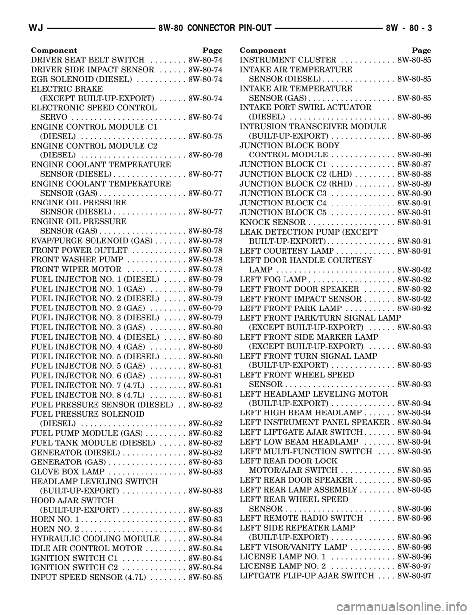
Component Page
DRIVER SEAT BELT SWITCH........ 8W-80-74
DRIVER SIDE IMPACT SENSOR...... 8W-80-74
EGR SOLENOID (DIESEL)........... 8W-80-74
ELECTRIC BRAKE
(EXCEPT BUILT-UP-EXPORT)...... 8W-80-74
ELECTRONIC SPEED CONTROL
SERVO ......................... 8W-80-74
ENGINE CONTROL MODULE C1
(DIESEL)....................... 8W-80-75
ENGINE CONTROL MODULE C2
(DIESEL)....................... 8W-80-76
ENGINE COOLANT TEMPERATURE
SENSOR (DIESEL)................ 8W-80-77
ENGINE COOLANT TEMPERATURE
SENSOR (GAS)................... 8W-80-77
ENGINE OIL PRESSURE
SENSOR (DIESEL)................ 8W-80-77
ENGINE OIL PRESSURE
SENSOR (GAS)................... 8W-80-78
EVAP/PURGE SOLENOID (GAS)....... 8W-80-78
FRONT POWER OUTLET............ 8W-80-78
FRONT WASHER PUMP............. 8W-80-78
FRONT WIPER MOTOR............. 8W-80-78
FUEL INJECTOR NO. 1 (DIESEL)..... 8W-80-79
FUEL INJECTOR NO. 1 (GAS)........ 8W-80-79
FUEL INJECTOR NO. 2 (DIESEL)..... 8W-80-79
FUEL INJECTOR NO. 2 (GAS)........ 8W-80-79
FUEL INJECTOR NO. 3 (DIESEL)..... 8W-80-79
FUEL INJECTOR NO. 3 (GAS)........ 8W-80-80
FUEL INJECTOR NO. 4 (DIESEL)..... 8W-80-80
FUEL INJECTOR NO. 4 (GAS)........ 8W-80-80
FUEL INJECTOR NO. 5 (DIESEL)..... 8W-80-80
FUEL INJECTOR NO. 5 (GAS)........ 8W-80-81
FUEL INJECTOR NO. 6 (GAS)........ 8W-80-81
FUEL INJECTOR NO. 7 (4.7L)........ 8W-80-81
FUEL INJECTOR NO. 8 (4.7L)........ 8W-80-81
FUEL PRESSURE SENSOR (DIESEL) . . 8W-80-82
FUEL PRESSURE SOLENOID
(DIESEL)....................... 8W-80-82
FUEL PUMP MODULE (GAS)......... 8W-80-82
FUEL TANK MODULE (DIESEL)...... 8W-80-82
GENERATOR (DIESEL).............. 8W-80-82
GENERATOR (GAS)................. 8W-80-83
GLOVE BOX LAMP................. 8W-80-83
HEADLAMP LEVELING SWITCH
(BUILT-UP-EXPORT).............. 8W-80-83
HOOD AJAR SWITCH
(BUILT-UP-EXPORT).............. 8W-80-83
HORN NO. 1....................... 8W-80-83
HORN NO. 2....................... 8W-80-84
HYDRAULIC COOLING MODULE..... 8W-80-84
IDLE AIR CONTROL MOTOR......... 8W-80-84
IGNITION SWITCH C1.............. 8W-80-84
IGNITION SWITCH C2.............. 8W-80-84
INPUT SPEED SENSOR (4.7L)........ 8W-80-85Component Page
INSTRUMENT CLUSTER............ 8W-80-85
INTAKE AIR TEMPERATURE
SENSOR (DIESEL)................ 8W-80-85
INTAKE AIR TEMPERATURE
SENSOR (GAS)................... 8W-80-85
INTAKE PORT SWIRL ACTUATOR
(DIESEL)....................... 8W-80-86
INTRUSION TRANSCEIVER MODULE
(BUILT-UP-EXPORT).............. 8W-80-86
JUNCTION BLOCK BODY
CONTROL MODULE.............. 8W-80-86
JUNCTION BLOCK C1.............. 8W-80-87
JUNCTION BLOCK C2 (LHD)......... 8W-80-88
JUNCTION BLOCK C2 (RHD)......... 8W-80-89
JUNCTION BLOCK C3.............. 8W-80-90
JUNCTION BLOCK C4.............. 8W-80-91
JUNCTION BLOCK C5.............. 8W-80-91
KNOCK SENSOR................... 8W-80-91
LEAK DETECTION PUMP (EXCEPT
BUILT-UP-EXPORT)............... 8W-80-91
LEFT COURTESY LAMP............. 8W-80-91
LEFT DOOR HANDLE COURTESY
LAMP.......................... 8W-80-92
LEFT FOG LAMP................... 8W-80-92
LEFT FRONT DOOR SPEAKER....... 8W-80-92
LEFT FRONT IMPACT SENSOR....... 8W-80-92
LEFT FRONT PARK LAMP........... 8W-80-92
LEFT FRONT PARK/TURN SIGNAL LAMP
(EXCEPT BUILT-UP-EXPORT)...... 8W-80-93
LEFT FRONT SIDE MARKER LAMP
(EXCEPT BUILT-UP-EXPORT)...... 8W-80-93
LEFT FRONT TURN SIGNAL LAMP
(BUILT-UP-EXPORT).............. 8W-80-93
LEFT FRONT WHEEL SPEED
SENSOR........................ 8W-80-93
LEFT HEADLAMP LEVELING MOTOR
(BUILT-UP-EXPORT).............. 8W-80-94
LEFT HIGH BEAM HEADLAMP....... 8W-80-94
LEFT INSTRUMENT PANEL SPEAKER . 8W-80-94
LEFT LIFTGATE AJAR SWITCH....... 8W-80-94
LEFT LOW BEAM HEADLAMP....... 8W-80-94
LEFT MULTI-FUNCTION SWITCH.... 8W-80-95
LEFT REAR DOOR LOCK
MOTOR/AJAR SWITCH............ 8W-80-95
LEFT REAR DOOR SPEAKER......... 8W-80-95
LEFT REAR LAMP ASSEMBLY........ 8W-80-95
LEFT REAR WHEEL SPEED
SENSOR........................ 8W-80-96
LEFT REMOTE RADIO SWITCH...... 8W-80-96
LEFT SIDE REPEATER LAMP
(BUILT-UP-EXPORT).............. 8W-80-96
LEFT VISOR/VANITY LAMP.......... 8W-80-96
LICENSE LAMP NO. 1.............. 8W-80-96
LICENSE LAMP NO. 2.............. 8W-80-97
LIFTGATE FLIP-UP AJAR SWITCH.... 8W-80-97
WJ8W-80 CONNECTOR PIN-OUT 8W - 80 - 3