lower control arm JEEP GRAND CHEROKEE 2002 WJ / 2.G User Guide
[x] Cancel search | Manufacturer: JEEP, Model Year: 2002, Model line: GRAND CHEROKEE, Model: JEEP GRAND CHEROKEE 2002 WJ / 2.GPages: 2199, PDF Size: 76.01 MB
Page 118 of 2199
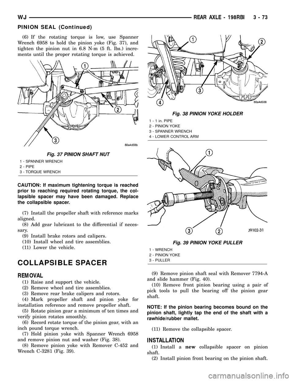
(6) If the rotating torque is low, use Spanner
Wrench 6958 to hold the pinion yoke (Fig. 37), and
tighten the pinion nut in 6.8 N´m (5 ft. lbs.) incre-
ments until the proper rotating torque is achieved.
CAUTION: If maximum tightening torque is reached
prior to reaching required rotating torque, the col-
lapsible spacer may have been damaged. Replace
the collapsible spacer.
(7) Install the propeller shaft with reference marks
aligned.
(8) Add gear lubricant to the differential if neces-
sary.
(9) Install brake rotors and calipers.
(10) Install wheel and tire assemblies.
(11) Lower the vehicle.
COLLAPSIBLE SPACER
REMOVAL
(1) Raise and support the vehicle.
(2) Remove wheel and tire assemblies.
(3) Remove rear brake calipers and rotors.
(4) Mark propeller shaft and pinion yoke for
installation reference and remove propeller shaft.
(5) Rotate pinion gear a minimum of ten times and
verify pinion rotates smoothly.
(6) Record rotate torque of the pinion gear, with an
inch pound torque wrench.
(7) Hold pinion yoke with Spanner Wrench 6958
and remove pinion nut and washer (Fig. 38).
(8) Remove pinion yoke with Remover C-452 and
Wrench C-3281 (Fig. 39).(9) Remove pinion shaft seal with Remover 7794-A
and slide hammer (Fig. 40).
(10) Remove front pinion bearing using a pair of
pick tools to pull the bearing off the pinion gear
shaft.
NOTE: If the pinion bearing becomes bound on the
pinion shaft, lightly tap the end of the shaft with a
rawhide/rubber mallet.
(11) Remove the collapsible spacer.
INSTALLATION
(1) Install anewcollapsible spacer on pinion
shaft.
(2) Install pinion front bearing on the pinion shaft.
Fig. 37 PINION SHAFT NUT
1 - SPANNER WRENCH
2 - PIPE
3 - TORQUE WRENCH
Fig. 38 PINION YOKE HOLDER
1 - 1 in. PIPE
2 - PINION YOKE
3 - SPANNER WRENCH
4 - LOWER CONTROL ARM
Fig. 39 PINION YOKE PULLER
1 - WRENCH
2 - PINION YOKE
3 - PULLER
WJREAR AXLE - 198RBI 3 - 73
PINION SEAL (Continued)
Page 129 of 2199
INSTALLATION
NOTE: If differential side bearings or differential
case are replaced, differential side bearing shim
requirements may change. Refer to Adjustments
(Differential Bearing Preload and Gear Backlash) for
procedures.
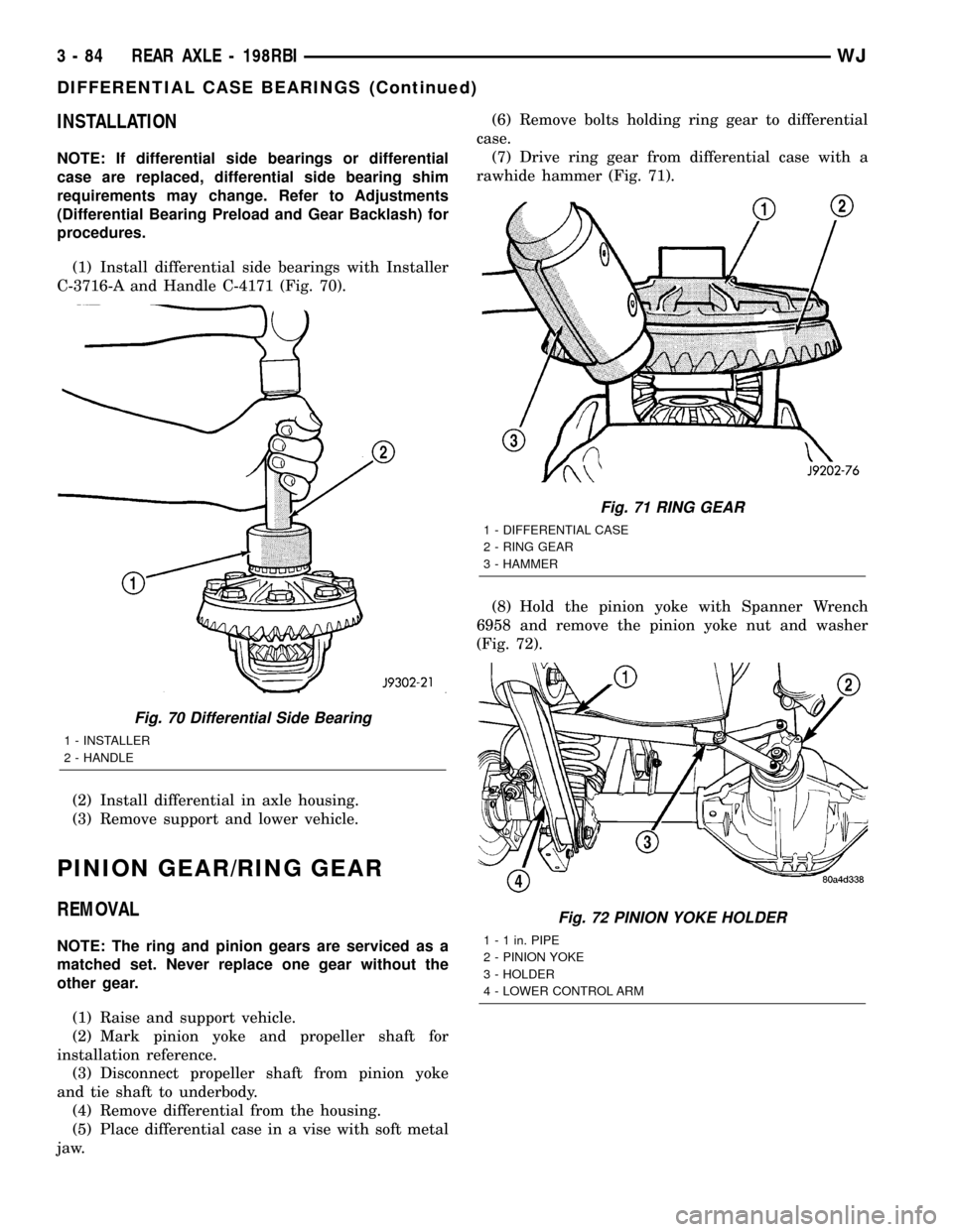
(1) Install differential side bearings with Installer
C-3716-A and Handle C-4171 (Fig. 70).
(2) Install differential in axle housing.
(3) Remove support and lower vehicle.
PINION GEAR/RING GEAR
REMOVAL
NOTE: The ring and pinion gears are serviced as a
matched set. Never replace one gear without the
other gear.
(1) Raise and support vehicle.
(2) Mark pinion yoke and propeller shaft for
installation reference.
(3) Disconnect propeller shaft from pinion yoke
and tie shaft to underbody.
(4) Remove differential from the housing.
(5) Place differential case in a vise with soft metal
jaw.(6) Remove bolts holding ring gear to differential
case.
(7) Drive ring gear from differential case with a
rawhide hammer (Fig. 71).
(8) Hold the pinion yoke with Spanner Wrench
6958 and remove the pinion yoke nut and washer
(Fig. 72).
Fig. 70 Differential Side Bearing
1 - INSTALLER
2 - HANDLE
Fig. 71 RING GEAR
1 - DIFFERENTIAL CASE
2 - RING GEAR
3 - HAMMER
Fig. 72 PINION YOKE HOLDER
1 - 1 in. PIPE
2 - PINION YOKE
3 - HOLDER
4 - LOWER CONTROL ARM
3 - 84 REAR AXLE - 198RBIWJ
DIFFERENTIAL CASE BEARINGS (Continued)
Page 156 of 2199
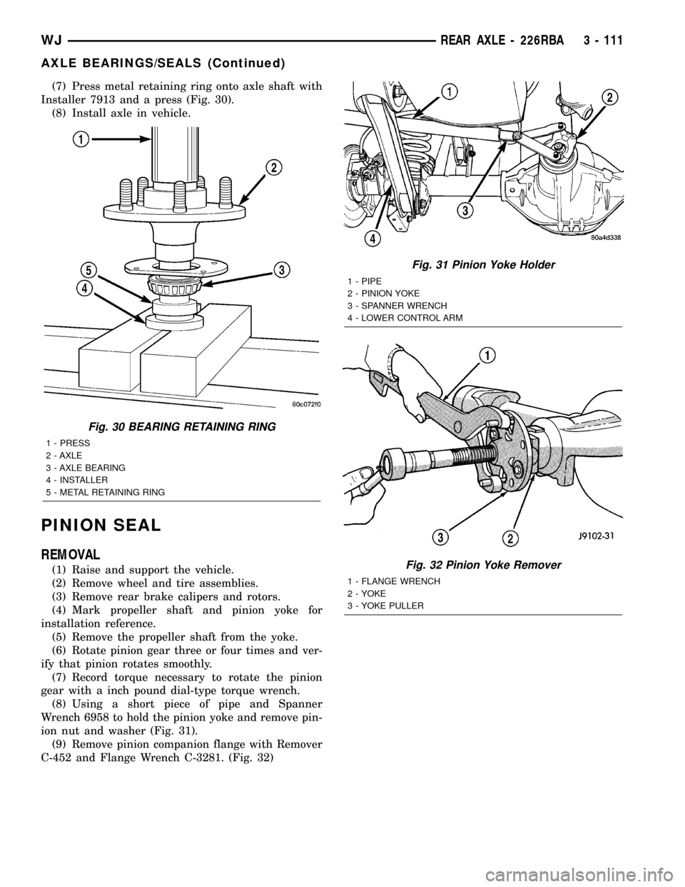
(7) Press metal retaining ring onto axle shaft with
Installer 7913 and a press (Fig. 30).
(8) Install axle in vehicle.
PINION SEAL
REMOVAL
(1) Raise and support the vehicle.
(2) Remove wheel and tire assemblies.
(3) Remove rear brake calipers and rotors.
(4) Mark propeller shaft and pinion yoke for
installation reference.
(5) Remove the propeller shaft from the yoke.
(6) Rotate pinion gear three or four times and ver-
ify that pinion rotates smoothly.
(7) Record torque necessary to rotate the pinion
gear with a inch pound dial-type torque wrench.
(8) Using a short piece of pipe and Spanner
Wrench 6958 to hold the pinion yoke and remove pin-
ion nut and washer (Fig. 31).
(9) Remove pinion companion flange with Remover
C-452 and Flange Wrench C-3281. (Fig. 32)
Fig. 30 BEARING RETAINING RING
1 - PRESS
2 - AXLE
3 - AXLE BEARING
4 - INSTALLER
5 - METAL RETAINING RING
Fig. 31 Pinion Yoke Holder
1 - PIPE
2 - PINION YOKE
3 - SPANNER WRENCH
4 - LOWER CONTROL ARM
Fig. 32 Pinion Yoke Remover
1 - FLANGE WRENCH
2 - YOKE
3 - YOKE PULLER
WJREAR AXLE - 226RBA 3 - 111
AXLE BEARINGS/SEALS (Continued)
Page 158 of 2199
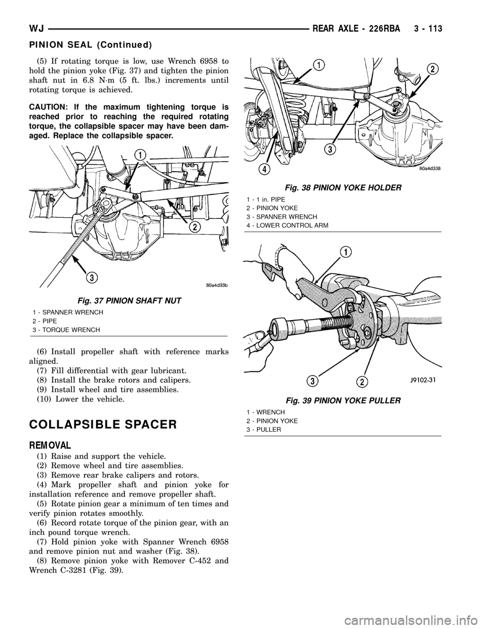
(5) If rotating torque is low, use Wrench 6958 to
hold the pinion yoke (Fig. 37) and tighten the pinion
shaft nut in 6.8 N´m (5 ft. lbs.) increments until
rotating torque is achieved.
CAUTION: If the maximum tightening torque is
reached prior to reaching the required rotating
torque, the collapsible spacer may have been dam-
aged. Replace the collapsible spacer.
(6) Install propeller shaft with reference marks
aligned.
(7) Fill differential with gear lubricant.
(8) Install the brake rotors and calipers.
(9) Install wheel and tire assemblies.
(10) Lower the vehicle.
COLLAPSIBLE SPACER
REMOVAL
(1) Raise and support the vehicle.
(2) Remove wheel and tire assemblies.
(3) Remove rear brake calipers and rotors.
(4) Mark propeller shaft and pinion yoke for
installation reference and remove propeller shaft.
(5) Rotate pinion gear a minimum of ten times and
verify pinion rotates smoothly.
(6) Record rotate torque of the pinion gear, with an
inch pound torque wrench.
(7) Hold pinion yoke with Spanner Wrench 6958
and remove pinion nut and washer (Fig. 38).
(8) Remove pinion yoke with Remover C-452 and
Wrench C-3281 (Fig. 39).
Fig. 37 PINION SHAFT NUT
1 - SPANNER WRENCH
2 - PIPE
3 - TORQUE WRENCH
Fig. 38 PINION YOKE HOLDER
1 - 1 in. PIPE
2 - PINION YOKE
3 - SPANNER WRENCH
4 - LOWER CONTROL ARM
Fig. 39 PINION YOKE PULLER
1 - WRENCH
2 - PINION YOKE
3 - PULLER
WJREAR AXLE - 226RBA 3 - 113
PINION SEAL (Continued)
Page 169 of 2199
CAUTION: Vari-lokTplenum must be seated against
the differential case prior to installing the ring gear
side differential bearing.
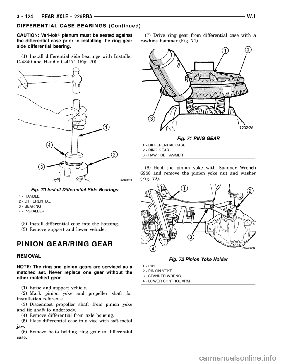
(1) Install differential side bearings with Installer
C-4340 and Handle C-4171 (Fig. 70).
(2) Install differential case into the housing.
(3) Remove support and lower vehicle.
PINION GEAR/RING GEAR
REMOVAL
NOTE: The ring and pinion gears are serviced as a
matched set. Never replace one gear without the
other matched gear.
(1) Raise and support vehicle.
(2) Mark pinion yoke and propeller shaft for
installation reference.
(3) Disconnect propeller shaft from pinion yoke
and tie shaft to underbody.
(4) Remove differential from axle housing.
(5) Place differential case in a vise with soft metal
jaw.
(6) Remove bolts holding ring gear to differential
case.(7) Drive ring gear from differential case with a
rawhide hammer (Fig. 71).
(8) Hold the pinion yoke with Spanner Wrench
6958 and remove the pinion yoke nut and washer
(Fig. 72).
Fig. 70 Install Differential Side Bearings
1 - HANDLE
2 - DIFFERENTIAL
3 - BEARING
4 - INSTALLER
Fig. 71 RING GEAR
1 - DIFFERENTIAL CASE
2 - RING GEAR
3 - RAWHIDE HAMMER
Fig. 72 Pinion Yoke Holder
1 - PIPE
2 - PINION YOKE
3 - SPANNER WRENCH
4 - LOWER CONTROL ARM
3 - 124 REAR AXLE - 226RBAWJ
DIFFERENTIAL CASE BEARINGS (Continued)
Page 235 of 2199
accessory drive belt (Refer to 7 - COOLING/ACCES-
SORY DRIVE/DRIVE BELTS - REMOVAL).
Add coolant to radiator to bring level to within 6.3
mm (1/4 in) of top of thermostat housing.
CAUTION: Avoid overheating. Do not operate
engine for an excessive period of time. Open drain-
cock immediately after test to eliminate boil over.
Start engine and accelerate rapidly three times, to
approximately 3000 rpm while observing coolant. If
internal engine combustion gases are leaking into
cooling system, bubbles will appear in coolant. If bub-
bles do not appear, internal combustion gas leakage
is not present.
DIAGNOSIS AND TESTING - COOLING SYSTEM
DEAERATION
As the engine operates, any air trapped in cooling
system gathers under the radiator cap. The next time
the engine is operated, thermal expansion of coolant
will push any trapped air past radiator cap into the
coolant reserve/overflow tank. Here it escapes to the
atmosphere into the tank. When the engine cools
down the coolant, it will be drawn from the reserve/
overflow tank into the radiator to replace any
removed air.
STANDARD PROCEDURE
STANDARD PROCEDUREÐDRAINING COOLING
SYSTEM 4.7L ENGINE
WARNING: DO NOT REMOVE THE CYLINDER
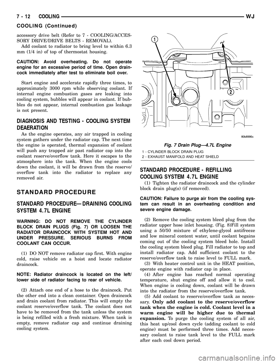
BLOCK DRAIN PLUGS (Fig. 7) OR LOOSEN THE
RADIATOR DRAINCOCK WITH SYSTEM HOT AND
UNDER PRESSURE. SERIOUS BURNS FROM
COOLANT CAN OCCUR.
(1) DO NOT remove radiator cap first. With engine
cold, raise vehicle on a hoist and locate radiator
draincock.
NOTE: Radiator draincock is located on the left/
lower side of radiator facing to rear of vehicle.
(2) Attach one end of a hose to the draincock. Put
the other end into a clean container. Open draincock
and drain coolant from radiator. This will empty the
coolant reserve/overflow tank. The coolant does not
have to be removed from the tank unless the system
is being refilled with a fresh mixture. When tank is
empty, remove radiator cap and continue draining
cooling system.
STANDARD PROCEDURE - REFILLING
COOLING SYSTEM 4.7L ENGINE
(1) Tighten the radiator draincock and the cylinder
block drain plug(s) (if removed).
CAUTION: Failure to purge air from the cooling sys-
tem can result in an overheating condition and
severe engine damage.
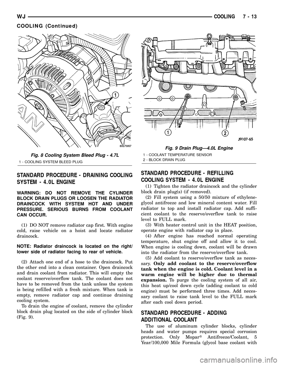
(2) Remove the cooling system bleed plug from the
radiator upper hose inlet housing. (Fig. 8)Fill system
using a 50/50 mixture of ethylene-glycol antifreeze
and low mineral content water, until coolant begains
coming out of the cooling system bleed hole. Install
the cooling system bleed plug. Fill radiator to top and
install radiator cap. Add sufficient coolant to the
reserve/overflow tank to raise level to FULL mark.
(3) With heater control unit in the HEAT position,
operate engine with radiator cap in place.
(4) After engine has reached normal operating
temperature, shut engine off and allow it to cool.
When engine is cooling down, coolant will be drawn
into the radiator from the reserve/overflow tank.
(5) Add coolant to reserve/overflow tank as neces-
sary.Only add coolant to the reserve/overflow
tank when the engine is cold. Coolant level in a
warm engine will be higher due to thermal
expansion.To purge the cooling system of all air,
this heat up/cool down cycle (adding coolant to cold
engine) must be performed three times. Add neces-
sary coolant to raise tank level to the FULL mark
after each cool down period.
Fig. 7 Drain PlugÐ4.7L Engine
1 - CYLINDER BLOCK DRAIN PLUG
2 - EXHAUST MANIFOLD AND HEAT SHIELD
7 - 12 COOLINGWJ
COOLING (Continued)
Page 236 of 2199
STANDARD PROCEDURE - DRAINING COOLING
SYSTEM - 4.0L ENGINE
WARNING: DO NOT REMOVE THE CYLINDER
BLOCK DRAIN PLUGS OR LOOSEN THE RADIATOR
DRAINCOCK WITH SYSTEM HOT AND UNDER
PRESSURE. SERIOUS BURNS FROM COOLANT
CAN OCCUR.
(1) DO NOT remove radiator cap first. With engine
cold, raise vehicle on a hoist and locate radiator
draincock.
NOTE: Radiator draincock is located on the right/
lower side of radiator facing to rear of vehicle.
(2) Attach one end of a hose to the draincock. Put
the other end into a clean container. Open draincock
and drain coolant from radiator. This will empty the
coolant reserve/overflow tank. The coolant does not
have to be removed from the tank unless the system
is being refilled with a fresh mixture. When tank is
empty, remove radiator cap and continue draining
cooling system.
To drain the engine of coolant, remove the cylinder
block drain plug located on the side of cylinder block
(Fig. 9).
STANDARD PROCEDURE - REFILLING
COOLING SYSTEM - 4.0L ENGINE
(1) Tighten the radiator draincock and the cylinder
block drain plug(s) (if removed).
(2) Fill system using a 50/50 mixture of ethylene-
glycol antifreeze and low mineral content water. Fill
radiator to top and install radiator cap. Add suffi-
cient coolant to the reserve/overflow tank to raise
level to FULL mark.
(3) With heater control unit in the HEAT position,
operate engine with radiator cap in place.
(4) After engine has reached normal operating
temperature, shut engine off and allow it to cool.
When engine is cooling down, coolant will be drawn
into the radiator from the reserve/overflow tank.
(5) Add coolant to reserve/overflow tank as neces-
sary.Only add coolant to the reserve/overflow
tank when the engine is cold. Coolant level in a
warm engine will be higher due to thermal
expansion.To purge the cooling system of all air,
this heat up/cool down cycle (adding coolant to cold
engine) must be performed three times. Add neces-
sary coolant to raise tank level to the FULL mark
after each cool down period.
STANDARD PROCEDURE - ADDING
ADDITIONAL COOLANT
The use of aluminum cylinder blocks, cylinder
heads and water pumps requires special corrosion
protection. Only MopartAntifreeze/Coolant, 5
Year/100,000 Mile Formula (glycol base coolant with
Fig. 8 Cooling System Bleed Plug - 4.7L
1 - COOLING SYSTEM BLEED PLUG
Fig. 9 Drain PlugÐ4.0L Engine
1 - COOLANT TEMPERATURE SENSOR
2 - BLOCK DRAIN PLUG
WJCOOLING 7 - 13
COOLING (Continued)
Page 270 of 2199

INSPECTION
The radiator cooling fins should be checked for
damage or deterioration. Inspect cooling fins to make
sure they are not bent or crushed, these areas result
in reduced heat exchange causing the cooling system
to operate at higher temperatures. Inspect the plastic
end tanks for cracks, damage or leaks.
Inspect the radiator neck for damage or distortion.
INSTALLATION
CAUTION: Before installing the radiator or A/C con-
denser, be sure the radiator-to-body and radiator-to-
A/C condenser rubber air seals (Fig. 39) are
properly fastened to their original positions. These
are used at the top, bottom and sides of the radia-
tor and A/C condenser. To prevent overheating,
these seals must be installed to their original posi-
tions.
(1) Equipped with air conditioning: Gently lower
the radiator into the vehicle. Guide the two radiator
alignment dowels through the holes in the rubber air
seals first and then through the A/C support brackets
(Fig. 40). Continue to guide the alignment dowels
into the rubber grommets located in lower radiator
crossmember. The holes in the L-shaped brackets
(located on bottom of A/C condenser) must be posi-
tioned between bottom of rubber air seals and top of
rubber grommets.
(2) Connect the radiator upper and lower hoses
and hose clamps to radiator (Fig. 41).
CAUTION: The tangs on the hose clamps must be
positioned straight down.
(3) Install coolant reserve/overflow tank hose at
radiator (Fig. 41).
(4) Connect both transmission cooler lines at the
radiator (Fig. 41).
(5) Install both radiator mounting bolts (Fig. 41).
(6) Install air inlet duct at grill.
(7) Attach electric fan harness to shroud, then con-
nect harness to connector (Fig. 41).
(8) Install the grill (Refer to 23 - BODY/EXTERI-
OR/GRILLE - INSTALLATION).
(9) Install the fan/viscous fan drive assembly to
the water pump.
(10) Rotate the fan blades (by hand) and check for
interference at fan shroud.
(11) Be sure of at least 25 mm (1.0 inch) between
tips of fan blades and fan shroud.
(12) Fill cooling system (Refer to 7 - COOLING -
STANDARD PROCEDURE).
(13) Connect battery cable at battery.
(14) Start and warm engine. Check for leaks.
RADIATOR FAN MOTOR
DIAGNOSIS AND TESTINGÐELECTRIC
COOLING FAN
The powertrain control module (PCM) will enter a
diagnostic trouble code (DTC) in memory if it detects
a problem in the auxiliary cooling fan relay or circuit.
(Refer to 25 - EMISSIONS CONTROL - DESCRIP-
TION).
If the electric cooling fan is inoperative, check the
15A fuse in the junction block and the 40A fuse in
the Power Distribution Center (PDC) with a 12 volt
test lamp or DVOM. Refer to the inside of the PDC
cover for the exact location of the fuse. If fuses are
okay, refer to ELECTRICAL for cooling fan and relay
circuit schematic.
WATER PUMP - 4.7L
DESCRIPTION
DESCRIPTIONÐWATER PUMP
A centrifugal water pump circulates coolant
through the water jackets, passages, intake manifold,
radiator core, cooling system hoses and heater core.
The pump is driven from the engine crankshaft by a
single serpentine drive belt.
The water pump impeller is pressed onto the rear
of a shaft that rotates in bearings pressed into the
housing. The housing has two small holes to allow
seepage to escape. The water pump seals are lubri-
cated by the antifreeze in the coolant mixture. No
additional lubrication is necessary.
Both heater hoses are connected to fittings on the
timing chain front cover. The water pump is also
mounted directly to the timing chain cover and is
equipped with a non serviceable integral pulley (Fig.
42).
DESCRIPTIONÐWATER PUMP BYPASS
The 4.7L engine uses an internal water/coolant
bypass system. The design uses galleries in the tim-
ing chain cover to circulate coolant during engine
warm-up preventing the coolant from flowing
through the radiator. The thermostat uses a stub
shaft located at the rear of the thermostat (Fig. 43)
to control flow through the bypass gallery.
OPERATION
OPERATIONÐWATER PUMP
A centrifugal water pump circulates coolant
through the water jackets, passages, intake manifold,
WJENGINE 7 - 47
RADIATOR - 4.0L (Continued)
Page 544 of 2199
following procedure should be performed using a
DRBIIItscan tool to verify the status of both airbag
squibs before either deployed airbag is removed from
the vehicle for disposal.
CAUTION: Deployed front airbags having two initia-
tors (squibs) in the airbag inflator may or may not
have live pyrotechnic material within the inflator. Do
not dispose of these airbags unless you are sure of
complete deployment. Refer to the Hazardous Sub-
stance Control System for proper disposal proce-
dures. Dispose of all non-deployed and deployed
airbags in a manner consistent with state, provin-
cial, local, and federal regulations.(1) Be certain that the DRBIIItscan tool contains
the latest version of the proper DRBIIItsoftware.
Connect the DRBIIItto the 16-way Data Link Con-
nector (DLC). The DLC is located on the driver side
lower edge of the instrument panel, outboard of the
steering column.
(2) Turn the ignition switch to the On position.
(3) Using the DRBIIIt, read and record the active
(current) Diagnostic Trouble Code (DTC) data.
Using the active DTC information, refer to theAir-
bag Squib Statustable to determine the status of
both driver and/or passenger airbag squibs.
AIRBAG SQUIB STATUS
IF the Active DTC is: Conditions Squib Status
Driver or Passenger Squib 1
openANDthe stored DTC minutes for both Driver
or Passenger squibs are within 15 minutes of
each otherBoth Squib 1 and 2 were
used.
Driver or Passenger Squib 2
open
Driver or Passenger Squib 1
openANDthe stored DTC minutes for Driver or
Passenger Squib 2 open is GREATER than the
stored DTC minutes for Driver or Passenger
Squib 1 by 15 minutes or moreSquib 1 was used; Squib 2 is
live.
Driver or Passenger Squib 2
open
Driver or Passenger Squib 1
openANDthe stored DTC minutes for Driver or
Passenger Squib 1 open is GREATER than the
stored DTC minutes for Driver or Passenger
Squib 2 by 15 minutes or moreSquib 1 is live; Squib 2 was
used.
Driver or Passenger Squib 2
open
Driver or Passenger Squib 1
openANDDriver or Passenger Squib 2 open is NOT
an active codeSquib 1 was used; Squib 2 is
live.
Driver or Passenger Squib 2
openANDDriver or Passenger Squib 1 open is NOT
an active codeSquib 1 is live; Squib 2 was
used.
Ifnone of the Driver or Passenger Squib 1 or 2
open are active codes, the status of the airbag squibs
is unknown. In this case the airbag should be han-
dled and disposed of as if the squibs were both live.
CLEANUP PROCEDURE
Following a supplemental restraint deployment,
the vehicle interior will contain a powdery residue.
This residue consists primarily of harmless particu-
late by-products of the small pyrotechnic charge that
initiates the propellant used to deploy a supplemen-
tal restraint. However, this residue may also contain
traces of sodium hydroxide powder, a chemical
by-product of the propellant material that is used to
generate the inert gas that inflates the airbag. Since
sodium hydroxide powder can irritate the skin, eyes,
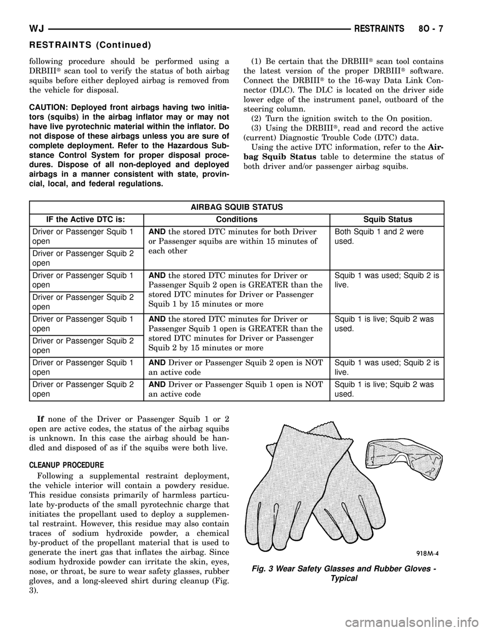
nose, or throat, be sure to wear safety glasses, rubber
gloves, and a long-sleeved shirt during cleanup (Fig.
3).
Fig. 3 Wear Safety Glasses and Rubber Gloves -
Typical
WJRESTRAINTS 8O - 7
RESTRAINTS (Continued)
Page 607 of 2199

OPERATION
The Vehicle Theft Security System (VTSS) indica-
tor gives a visible indication of the VTSS arming sta-
tus. One side of Light-Emittiong Diode (LED) in the
VTSS indicator is connected to unswitched battery
current through a fused B(+) circuit and a fuse in the
Junction Block (JB). The other side of the LED is
hard wired to the Body Control Module (BCM), which
controls the operation of the VTSS indicator by pull-
ing this side of the LED circuit to ground. When the
VTSS arming is in progress, the BCM will flash the
LED rapidly on and off for about fifteen seconds.
When the VTSS has been successfully armed, the
BCM will flash the LED on and off continually at a
much slower rate until the VTSS has been disarmed.
The VTSS indicator can be diagnosed using conven-
tional diagnostic tools and methods.
DIAGNOSIS AND TESTING - VTSS INDICATOR
The diagnosis found here addresses an inoperative
Vehicle Theft Security System (VTSS) indicator con-
dition. If the problem being diagnosed is related to
indicator accuracy, be certain to confirm that the
problem is with the indicator and not with an inop-
erative VTSS. (Refer to 8 - ELECTRICAL/VEHICLE
THEFT SECURITY - DIAGNOSIS AND TESTING -
VEHICLE THEFT SECURITY SYSTEM). If no VTSS
problem is found, the following procedure will help to
locate a short or open in the VTSS indicator control
circuit. Refer to the appropriate wiring information.
WARNING: ON VEHICLES EQUIPPED WITH AIR-
BAGS, DISABLE THE AIRBAG SYSTEM BEFORE
ATTEMPTING ANY STEERING WHEEL, STEERING
COLUMN, OR INSTRUMENT PANEL COMPONENT
DIAGNOSIS OR SERVICE. DISCONNECT AND ISO-
LATE THE BATTERY NEGATIVE (GROUND) CABLE,
THEN WAIT TWO MINUTES FOR THE AIRBAG SYS-
TEM CAPACITOR TO DISCHARGE BEFORE PER-
FORMING FURTHER DIAGNOSIS OR SERVICE. THIS
IS THE ONLY SURE WAY TO DISABLE THE AIRBAG
SYSTEM. FAILURE TO TAKE THE PROPER PRE-CAUTIONS COULD RESULT IN ACCIDENTAL AIR-
BAG DEPLOYMENT AND POSSIBLE PERSONAL
INJURY.
(1) Check the fused B(+) fuse in the Junction
Block (JB). If OK, go to Step 2. If not OK, repair the
shorted circuit or component and replace the faulty
fuse.
(2) Check for battery voltage at the fused B(+) fuse
in the JB. If OK, go to Step 3. If not OK, repair the
open fused B(+) circuit between the JB and the
Power Distribution Center (PDC).
(3) Disconnect and isolate the battery negative
cable. Disconnect the instrument panel wire harness
connector for the automatic headlamp light sensor/
VTSS indicator from the automatic headlamp light
sensor/VTSS indicator pigtail wire connector. Recon-
nect the battery negative cable. Check for battery
voltage at the fused B(+) circuit cavity of the instru-
ment panel wire harness connector for the automatic
headlamp light sensor/VTSS indicator. If OK, go to
Step 4. If not OK, repair the open fused B(+) circuit
between the VTSS indicator and the JB.
(4) Disconnect and isolate the battery negative
cable. Disconnect the instrument panel wire harness
connector for the JB from the JB connector recepta-
cle. Check for continuity between the VTSS indicator
driver circuit cavity of the instrument panel wire
harness connector for the automatic headlamp light
sensor/VTSS indicator and a good ground. There
should be no continuity. If OK, go to Step 5. If not
OK, repair the shorted VTSS indicator driver circuit
between the VTSS indicator and the JB.
(5) Check for continuity between the VTSS indica-
tor driver circuit of the instrument panel wire har-
ness connector for the automatic headlamp light
sensor/VTSS indicator and the instrument panel wire
harness connector for the JB. There should be conti-
nuity. If OK, replace the faulty VTSS indicator. If not
OK, repair the open VTSS indicator driver circuit
between the VTSS indicator and the JB.
8Q - 16 VEHICLE THEFT SECURITYWJ
VTSS INDICATOR (Continued)