service JEEP GRAND CHEROKEE 2002 WJ / 2.G User Guide
[x] Cancel search | Manufacturer: JEEP, Model Year: 2002, Model line: GRAND CHEROKEE, Model: JEEP GRAND CHEROKEE 2002 WJ / 2.GPages: 2199, PDF Size: 76.01 MB
Page 31 of 2199
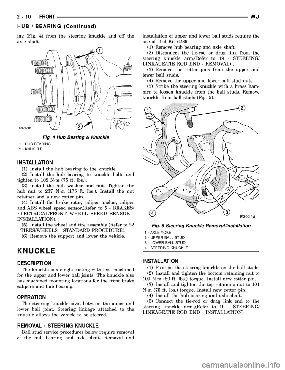
ing (Fig. 4) from the steering knuckle and off the
axle shaft.
INSTALLATION
(1) Install the hub bearing to the knuckle.
(2) Install the hub bearing to knuckle bolts and
tighten to 102 N´m (75 ft. lbs.).
(3) Install the hub washer and nut. Tighten the
hub nut to 237 N´m (175 ft. lbs.). Install the nut
retainer and a new cotter pin.
(4) Install the brake rotor, caliper anchor, caliper
and ABS wheel speed sensor,(Refer to 5 - BRAKES/
ELECTRICAL/FRONT WHEEL SPEED SENSOR -
INSTALLATION).
(5) Install the wheel and tire assembly (Refer to 22
- TIRES/WHEELS - STANDARD PROCEDURE).
(6) Remove the support and lower the vehicle.
KNUCKLE
DESCRIPTION
The knuckle is a single casting with legs machined
for the upper and lower ball joints. The knuckle also
has machined mounting locations for the front brake
calipers and hub bearing.
OPERATION
The steering knuckle pivot between the upper and
lower ball joint. Steering linkage attached to the
knuckle allows the vehicle to be steered.
REMOVAL - STEERING KNUCKLE
Ball stud service procedures below require removal
of the hub bearing and axle shaft. Removal andinstallation of upper and lower ball studs require the
use of Tool Kit 6289.
(1) Remove hub bearing and axle shaft.
(2) Disconnect the tie-rod or drag link from the
steering knuckle arm,(Refer to 19 - STEERING/
LINKAGE/TIE ROD END - REMOVAL) .
(3) Remove the cotter pins from the upper and
lower ball studs.
(4) Remove the upper and lower ball stud nuts.
(5) Strike the steering knuckle with a brass ham-
mer to loosen knuckle from the ball studs. Remove
knuckle from ball studs (Fig. 5).
INSTALLATION
(1) Position the steering knuckle on the ball studs.
(2) Install and tighten the bottom retaining nut to
109 N´m (80 ft. lbs.) torque. Install new cotter pin.
(3) Install and tighten the top retaining nut to 101
N´m (75 ft. lbs.) torque. Install new cotter pin.
(4) Install the hub bearing and axle shaft.
(5) Connect the tie-rod or drag link end to the
steering knuckle arm.,(Refer to 19 - STEERING/
LINKAGE/TIE ROD END - INSTALLATION) .
Fig. 4 Hub Bearing & Knuckle
1 - HUB BEARING
2 - KNUCKLE
Fig. 5 Steering Knuckle Removal/Installation
1 - AXLE YOKE
2 - UPPER BALL STUD
3 - LOWER BALL STUD
4 - STEERING KNUCKLE
2 - 10 FRONTWJ
HUB / BEARING (Continued)
Page 32 of 2199
LOWER BALL JOINT
REMOVAL
Ball stud service procedures below require removal
of the hub bearing and axle shaft. Removal and
installation of upper and lower ball studs require the
use of Tool Kit 6289.
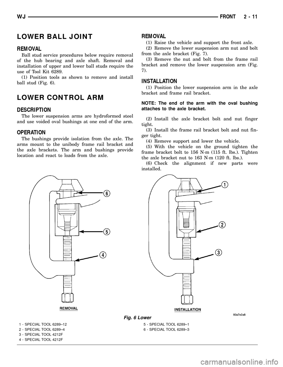
(1) Position tools as shown to remove and install
ball stud (Fig. 6).
LOWER CONTROL ARM
DESCRIPTION
The lower suspension arms are hydroformed steel
and use voided oval bushings at one end of the arm.
OPERATION
The bushings provide isolation from the axle. The
arms mount to the unibody frame rail bracket and
the axle brackets. The arm and bushings provide
location and react to loads from the axle.
REMOVAL
(1) Raise the vehicle and support the front axle.
(2) Remove the lower suspension arm nut and bolt
from the axle bracket (Fig. 7).
(3) Remove the nut and bolt from the frame rail
bracket and remove the lower suspension arm (Fig.
7).
INSTALLATION
(1) Position the lower suspension arm in the axle
bracket and frame rail bracket.
NOTE: The end of the arm with the oval bushing
attaches to the axle bracket.
(2) Install the axle bracket bolt and nut finger
tight.
(3) Install the frame rail bracket bolt and nut fin-
ger tight.
(4) Remove support and lower the vehicle.
(5) With the vehicle on the ground tighten the
frame bracket bolt to 156 N´m (115 ft. lbs.). Tighten
the axle bracket nut to 163 N´m (120 ft. lbs.).
(6) Check the alignment if new parts were
installed.
Fig. 6 Lower
1 - SPECIAL TOOL 6289±12
2 - SPECIAL TOOL 6289±4
3 - SPECIAL TOOL 4212F
4 - SPECIAL TOOL 4212F5 - SPECIAL TOOL 6289±1
6 - SPECIAL TOOL 6289±3
WJFRONT 2 - 11
Page 36 of 2199
(2) Install track bar to the frame rail bracket.
Install the bolt and nut finger tight.NOTE: It may be necessary to pry the axle assem-
bly over to install the track bar to the frame rail
bracket.
(3) Remove the supports and lower the vehicle.
(4) With the vehicle on the ground tighten the nut
at the frame rail bracket and to the bolt at the axle
bracket to 100 N´m (74 ft. lbs.).
(5) Check alignment specifications if a new track
bar was installed.
UPPER BALL JOINT
REMOVAL
Ball stud service procedures below require removal
of the hub bearing and axle shaft. Removal and
installation of upper and lower ball studs require the
use of Tool Kit 6289.
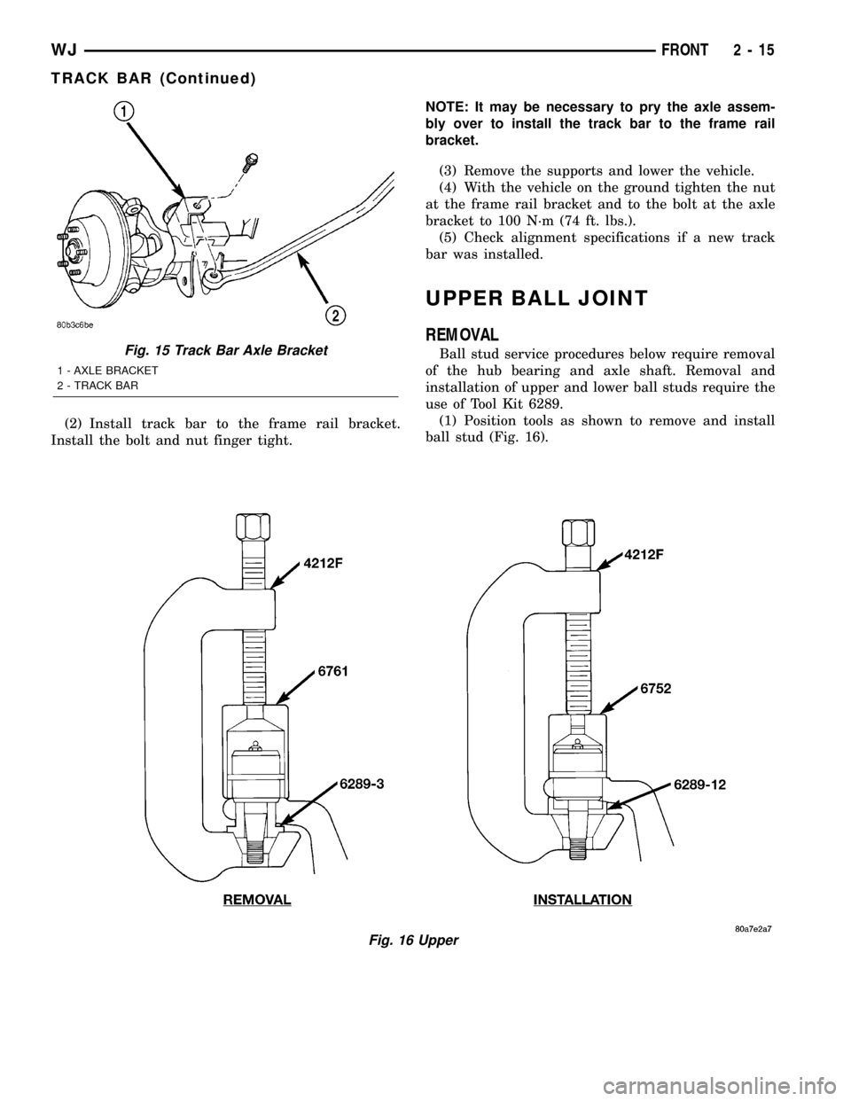
(1) Position tools as shown to remove and install
ball stud (Fig. 16).
Fig. 16 Upper
Fig. 15 Track Bar Axle Bracket
1 - AXLE BRACKET
2 - TRACK BAR
WJFRONT 2 - 15
TRACK BAR (Continued)
Page 53 of 2199
SINGLE CARDAN UNIVERSAL
JOINTS
DISASSEMBLY
NOTE: Individual components of cardan universal
joints are not serviceable. If worn or leaking, they
must be replaced as an assembly.
(1) Remove the propeller shaft.
(2) Tap the outside of the bearing cap assembly
with a drift to loosen snap ring.
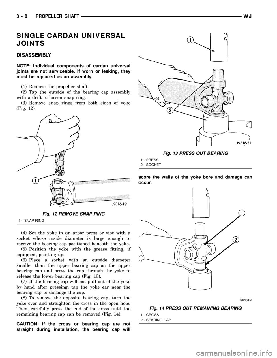
(3) Remove snap rings from both sides of yoke
(Fig. 12).
(4) Set the yoke in an arbor press or vise with a
socket whose inside diameter is large enough to
receive the bearing cap positioned beneath the yoke.
(5) Position the yoke with the grease fitting, if
equipped, pointing up.
(6) Place a socket with an outside diameter
smaller than the upper bearing cap on the upper
bearing cap and press the cap through the yoke to
release the lower bearing cap (Fig. 13).
(7) If the bearing cap will not pull out of the yoke
by hand after pressing, tap the yoke ear near the
bearing cap to dislodge the cap.
(8) To remove the opposite bearing cap, turn the
yoke over and straighten the cross in the open hole.
Then, carefully press the end of the cross until the
remaining bearing cap can be removed (Fig. 14).
CAUTION: If the cross or bearing cap are not
straight during installation, the bearing cap willscore the walls of the yoke bore and damage can
occur.
Fig. 12 REMOVE SNAP RING
1 - SNAP RING
Fig. 13 PRESS OUT BEARING
1 - PRESS
2 - SOCKET
Fig. 14 PRESS OUT REMAINING BEARING
1 - CROSS
2 - BEARING CAP
3 - 8 PROPELLER SHAFTWJ
Page 54 of 2199
ASSEMBLY
(1) Apply extreme pressure (EP) N.L.G.I. Grade 1
or 2 grease to inside of yoke bores.
(2) Position the cross in the yoke with its lube fit-
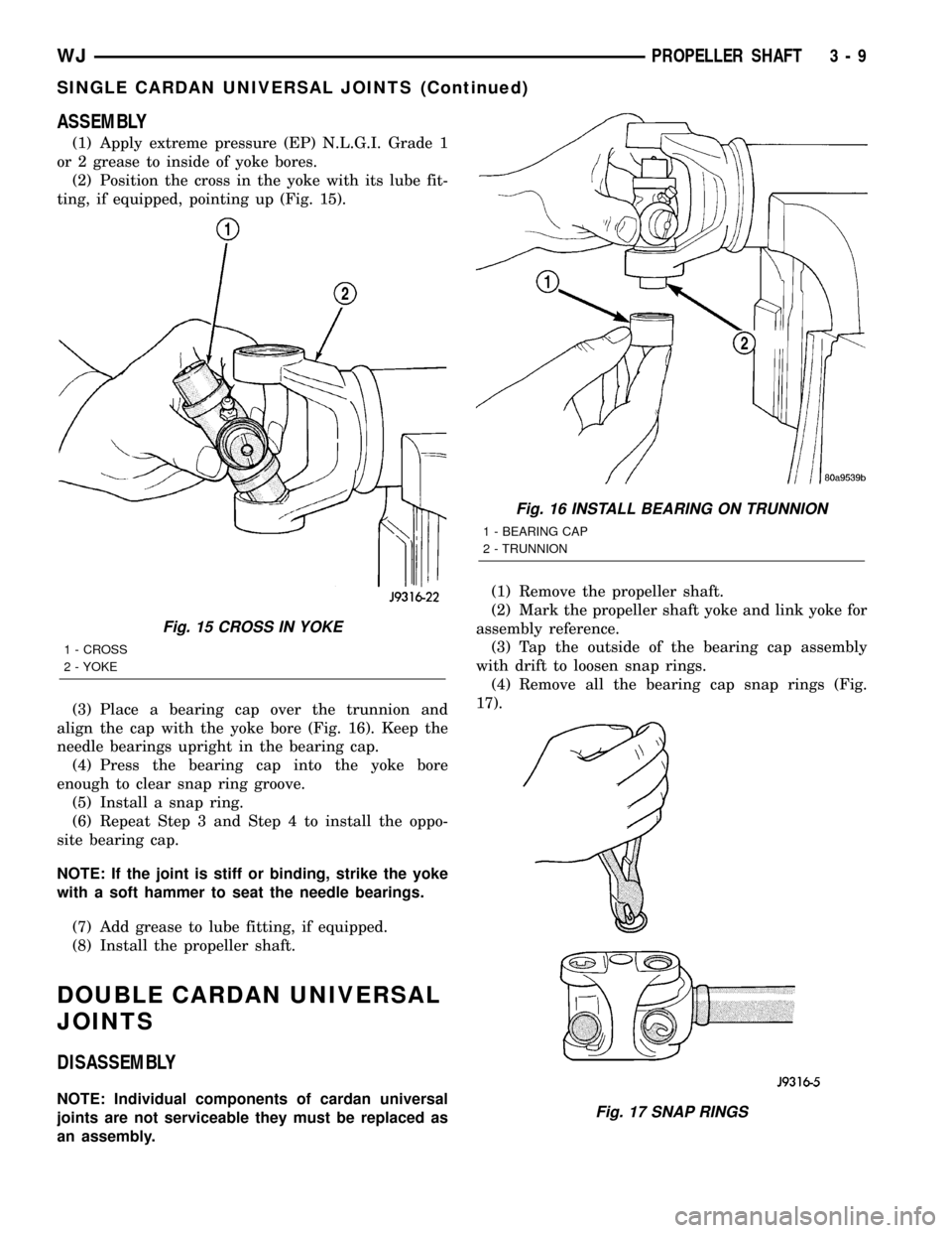
ting, if equipped, pointing up (Fig. 15).
(3) Place a bearing cap over the trunnion and
align the cap with the yoke bore (Fig. 16). Keep the
needle bearings upright in the bearing cap.
(4) Press the bearing cap into the yoke bore
enough to clear snap ring groove.
(5) Install a snap ring.
(6) Repeat Step 3 and Step 4 to install the oppo-
site bearing cap.
NOTE: If the joint is stiff or binding, strike the yoke
with a soft hammer to seat the needle bearings.
(7) Add grease to lube fitting, if equipped.
(8) Install the propeller shaft.
DOUBLE CARDAN UNIVERSAL
JOINTS
DISASSEMBLY
NOTE: Individual components of cardan universal
joints are not serviceable they must be replaced as
an assembly.(1) Remove the propeller shaft.
(2) Mark the propeller shaft yoke and link yoke for
assembly reference.
(3) Tap the outside of the bearing cap assembly
with drift to loosen snap rings.
(4) Remove all the bearing cap snap rings (Fig.
17).
Fig. 15 CROSS IN YOKE
1 - CROSS
2 - YOKE
Fig. 16 INSTALL BEARING ON TRUNNION
1 - BEARING CAP
2 - TRUNNION
Fig. 17 SNAP RINGS
WJPROPELLER SHAFT 3 - 9
SINGLE CARDAN UNIVERSAL JOINTS (Continued)
Page 61 of 2199
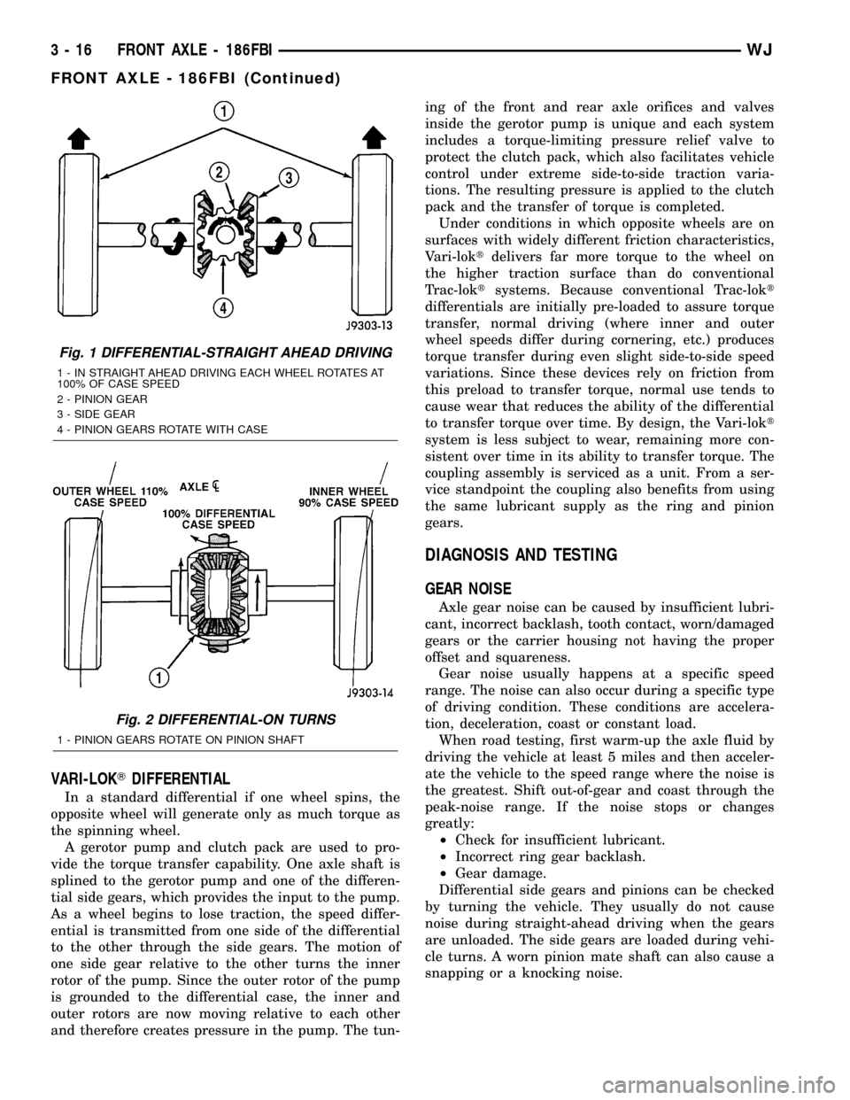
VARI-LOKTDIFFERENTIAL
In a standard differential if one wheel spins, the
opposite wheel will generate only as much torque as
the spinning wheel.
A gerotor pump and clutch pack are used to pro-
vide the torque transfer capability. One axle shaft is
splined to the gerotor pump and one of the differen-
tial side gears, which provides the input to the pump.
As a wheel begins to lose traction, the speed differ-
ential is transmitted from one side of the differential
to the other through the side gears. The motion of
one side gear relative to the other turns the inner
rotor of the pump. Since the outer rotor of the pump
is grounded to the differential case, the inner and
outer rotors are now moving relative to each other
and therefore creates pressure in the pump. The tun-ing of the front and rear axle orifices and valves
inside the gerotor pump is unique and each system
includes a torque-limiting pressure relief valve to
protect the clutch pack, which also facilitates vehicle
control under extreme side-to-side traction varia-
tions. The resulting pressure is applied to the clutch
pack and the transfer of torque is completed.
Under conditions in which opposite wheels are on
surfaces with widely different friction characteristics,
Vari-loktdelivers far more torque to the wheel on
the higher traction surface than do conventional
Trac-loktsystems. Because conventional Trac-lokt
differentials are initially pre-loaded to assure torque
transfer, normal driving (where inner and outer
wheel speeds differ during cornering, etc.) produces
torque transfer during even slight side-to-side speed
variations. Since these devices rely on friction from
this preload to transfer torque, normal use tends to
cause wear that reduces the ability of the differential
to transfer torque over time. By design, the Vari-lokt
system is less subject to wear, remaining more con-
sistent over time in its ability to transfer torque. The
coupling assembly is serviced as a unit. From a ser-
vice standpoint the coupling also benefits from using
the same lubricant supply as the ring and pinion
gears.
DIAGNOSIS AND TESTING
GEAR NOISE
Axle gear noise can be caused by insufficient lubri-
cant, incorrect backlash, tooth contact, worn/damaged
gears or the carrier housing not having the proper
offset and squareness.
Gear noise usually happens at a specific speed
range. The noise can also occur during a specific type
of driving condition. These conditions are accelera-
tion, deceleration, coast or constant load.
When road testing, first warm-up the axle fluid by
driving the vehicle at least 5 miles and then acceler-
ate the vehicle to the speed range where the noise is
the greatest. Shift out-of-gear and coast through the
peak-noise range. If the noise stops or changes
greatly:
²Check for insufficient lubricant.
²Incorrect ring gear backlash.
²Gear damage.
Differential side gears and pinions can be checked
by turning the vehicle. They usually do not cause
noise during straight-ahead driving when the gears
are unloaded. The side gears are loaded during vehi-
cle turns. A worn pinion mate shaft can also cause a
snapping or a knocking noise.
Fig. 1 DIFFERENTIAL-STRAIGHT AHEAD DRIVING
1 - IN STRAIGHT AHEAD DRIVING EACH WHEEL ROTATES AT
100% OF CASE SPEED
2 - PINION GEAR
3 - SIDE GEAR
4 - PINION GEARS ROTATE WITH CASE
Fig. 2 DIFFERENTIAL-ON TURNS
1 - PINION GEARS ROTATE ON PINION SHAFT
3 - 16 FRONT AXLE - 186FBIWJ
FRONT AXLE - 186FBI (Continued)
Page 64 of 2199
Condition Possible Causes Correction
Differential Gears Scored 1. Insufficient lubrication. 1. Replace scored gears. Fill
differential with the correct fluid type
and quantity.
2. Improper grade of lubricant. 2. Replace scored gears. Fill
differential with the correct fluid type
and quantity.
3. Excessive spinning of one
wheel/tire.3. Replace scored gears. Inspect all
gears, pinion bores, and shaft for
damage. Service as necessary.
Loss Of Lubricant 1. Lubricant level too high. 1. Drain lubricant to the correct
level.
2. Worn axle shaft seals. 2. Replace seals.
3. Cracked differential housing. 3. Repair as necessary.
4. Worn pinion seal. 4. Replace seal.
5. Worn/scored yoke. 5. Replace yoke and seal.
6. Axle cover not properly sealed. 6. Remove, clean, and re-seal
cover.
Axle Overheating 1. Lubricant level low. 1. Fill differential to correct level.
2. Improper grade of lubricant. 2. Fill differential with the correct
fluid type and quantity.
3. Bearing pre-loads too high. 3. Re-adjust bearing pre-loads.
4. Insufficient ring gear backlash. 4. Re-adjust ring gear backlash.
Gear Teeth Broke 1. Overloading. 1. Replace gears. Examine other
gears and bearings for possible
damage.
2. Erratic clutch operation. 2. Replace gears and examine the
remaining parts for damage. Avoid
erratic clutch operation.
3. Ice-spotted pavement. 3. Replace gears and examine
remaining parts for damage.
4. Improper adjustments. 4. Replace gears and examine
remaining parts for damage. Ensure
ring gear backlash is correct.
WJFRONT AXLE - 186FBI 3 - 19
FRONT AXLE - 186FBI (Continued)
Page 67 of 2199
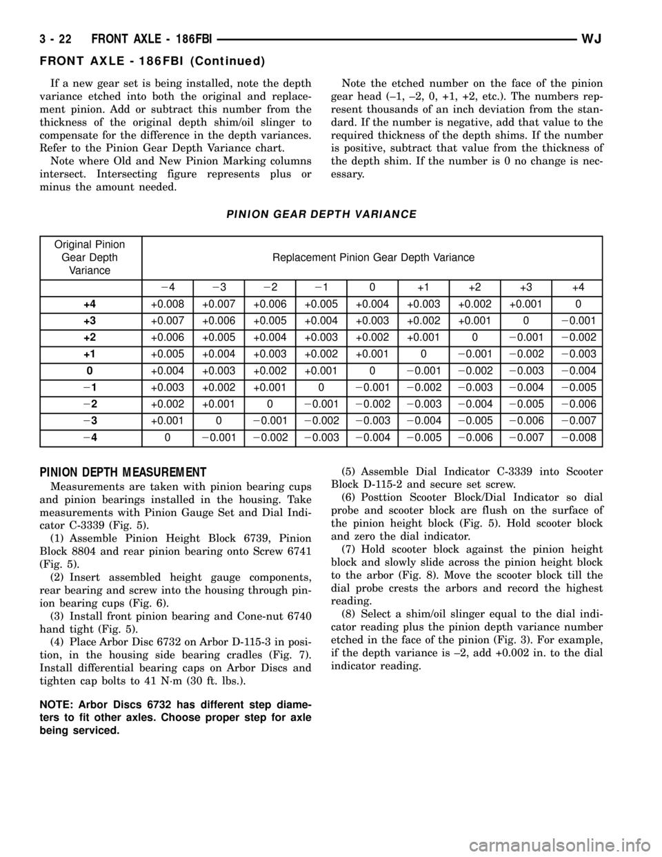
If a new gear set is being installed, note the depth
variance etched into both the original and replace-
ment pinion. Add or subtract this number from the
thickness of the original depth shim/oil slinger to
compensate for the difference in the depth variances.
Refer to the Pinion Gear Depth Variance chart.
Note where Old and New Pinion Marking columns
intersect. Intersecting figure represents plus or
minus the amount needed.Note the etched number on the face of the pinion
gear head (±1, ±2, 0, +1, +2, etc.). The numbers rep-
resent thousands of an inch deviation from the stan-
dard. If the number is negative, add that value to the
required thickness of the depth shims. If the number
is positive, subtract that value from the thickness of
the depth shim. If the number is 0 no change is nec-
essary.
PINION GEAR DEPTH VARIANCE
Original Pinion
Gear Depth
VarianceReplacement Pinion Gear Depth Variance
24232221 0 +1 +2 +3 +4
+4+0.008 +0.007 +0.006 +0.005 +0.004 +0.003 +0.002 +0.001 0
+3+0.007 +0.006 +0.005 +0.004 +0.003 +0.002 +0.001 020.001
+2+0.006 +0.005 +0.004 +0.003 +0.002 +0.001 020.00120.002
+1+0.005 +0.004 +0.003 +0.002 +0.001 020.00120.00220.003
0+0.004 +0.003 +0.002 +0.001 020.00120.00220.00320.004
21+0.003 +0.002 +0.001 020.00120.00220.00320.00420.005
22+0.002 +0.001 020.00120.00220.00320.00420.00520.006
23+0.001 020.00120.00220.00320.00420.00520.00620.007
24020.00120.00220.00320.00420.00520.00620.00720.008
PINION DEPTH MEASUREMENT
Measurements are taken with pinion bearing cups
and pinion bearings installed in the housing. Take
measurements with Pinion Gauge Set and Dial Indi-
cator C-3339 (Fig. 5).
(1) Assemble Pinion Height Block 6739, Pinion
Block 8804 and rear pinion bearing onto Screw 6741
(Fig. 5).
(2) Insert assembled height gauge components,
rear bearing and screw into the housing through pin-
ion bearing cups (Fig. 6).
(3) Install front pinion bearing and Cone-nut 6740
hand tight (Fig. 5).
(4) Place Arbor Disc 6732 on Arbor D-115-3 in posi-
tion, in the housing side bearing cradles (Fig. 7).
Install differential bearing caps on Arbor Discs and
tighten cap bolts to 41 N´m (30 ft. lbs.).
NOTE: Arbor Discs 6732 has different step diame-
ters to fit other axles. Choose proper step for axle
being serviced.(5) Assemble Dial Indicator C-3339 into Scooter
Block D-115-2 and secure set screw.
(6) Posttion Scooter Block/Dial Indicator so dial
probe and scooter block are flush on the surface of
the pinion height block (Fig. 5). Hold scooter block
and zero the dial indicator.
(7) Hold scooter block against the pinion height
block and slowly slide across the pinion height block
to the arbor (Fig. 8). Move the scooter block till the
dial probe crests the arbors and record the highest
reading.
(8) Select a shim/oil slinger equal to the dial indi-
cator reading plus the pinion depth variance number
etched in the face of the pinion (Fig. 3). For example,
if the depth variance is ±2, add +0.002 in. to the dial
indicator reading.
3 - 22 FRONT AXLE - 186FBIWJ
FRONT AXLE - 186FBI (Continued)
Page 79 of 2199
AXLE SHAFTS
REMOVAL
If the axle shaft and hub bearing are being
removed in order to service another component, the
axle shaft and hub bearing can be removed as an
assembly.
(1) Raise and support the vehicle.
(2) Remove the wheel and tire assembly.
(3) Remove brake caliper, rotor and ABS wheel
speed sensor.
(4) Remove cotter pin, nut retainer and axle nut.
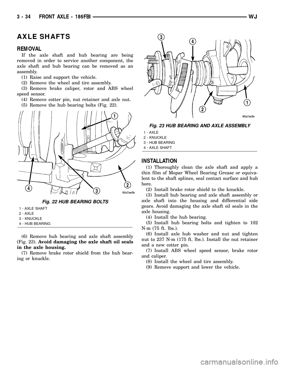
(5) Remove the hub bearing bolts (Fig. 22).
(6) Remove hub bearing and axle shaft assembly
(Fig. 23).Avoid damaging the axle shaft oil seals
in the axle housing.
(7) Remove brake rotor shield from the hub bear-
ing or knuckle.
INSTALLATION
(1) Thoroughly clean the axle shaft and apply a
thin film of Mopar Wheel Bearing Grease or equiva-
lent to the shaft splines, seal contact surface and hub
bore.
(2) Install brake rotor shield to the knuckle.
(3) Install hub bearing and axle shaft assembly or
axle shaft into the housing and differential side
gears. Avoid damaging the axle shaft oil seals in the
axle housing.
(4) Install the hub bearing.
(5) Install hub bearing bolts and tighten to 102
N´m (75 ft. lbs.).
(6) Install axle hub washer and nut and tighten
nut to 237 N´m (175 ft. lbs.). Install the nut retainer
and a new cotter pin.
(7) Install ABS wheel speed sensor, brake rotor
and caliper.
(8) Install the wheel and tire assembly.
(9) Remove support and lower the vehicle.
Fig. 22 HUB BEARING BOLTS
1 - AXLE SHAFT
2 - AXLE
3 - KNUCKLE
4 - HUB BEARING
Fig. 23 HUB BEARING AND AXLE ASSEMBLY
1 - AXLE
2 - KNUCKLE
3 - HUB BEARING
4 - AXLE SHAFT
3 - 34 FRONT AXLE - 186FBIWJ
Page 80 of 2199
AXLE SHAFT SEALS
REMOVAL
(1) Raise and support vehicle.
(2) Remove axle shafts.
(3) Remove differential assembly.
(4) Remove inner axle shaft seals with a pry bay.
INSTALLATION
(1) Remove any sealer remaining from original
seals.
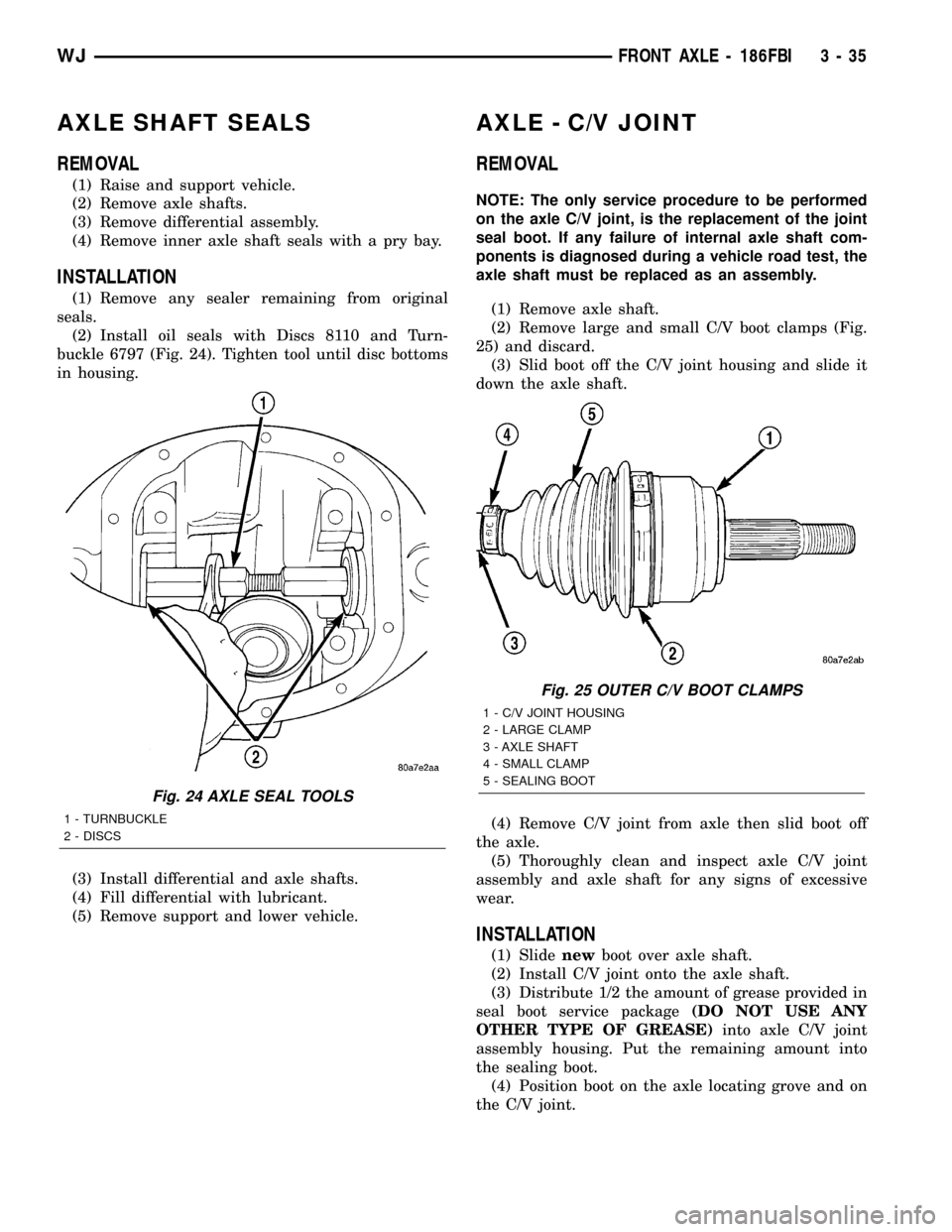
(2) Install oil seals with Discs 8110 and Turn-
buckle 6797 (Fig. 24). Tighten tool until disc bottoms
in housing.
(3) Install differential and axle shafts.
(4) Fill differential with lubricant.
(5) Remove support and lower vehicle.
AXLE - C/V JOINT
REMOVAL
NOTE: The only service procedure to be performed
on the axle C/V joint, is the replacement of the joint
seal boot. If any failure of internal axle shaft com-
ponents is diagnosed during a vehicle road test, the
axle shaft must be replaced as an assembly.
(1) Remove axle shaft.
(2) Remove large and small C/V boot clamps (Fig.
25) and discard.
(3) Slid boot off the C/V joint housing and slide it
down the axle shaft.
(4) Remove C/V joint from axle then slid boot off
the axle.
(5) Thoroughly clean and inspect axle C/V joint
assembly and axle shaft for any signs of excessive
wear.
INSTALLATION
(1) Slidenewboot over axle shaft.
(2) Install C/V joint onto the axle shaft.
(3) Distribute 1/2 the amount of grease provided in
seal boot service package(DO NOT USE ANY
OTHER TYPE OF GREASE)into axle C/V joint
assembly housing. Put the remaining amount into
the sealing boot.
(4) Position boot on the axle locating grove and on
the C/V joint.
Fig. 24 AXLE SEAL TOOLS
1 - TURNBUCKLE
2 - DISCS
Fig. 25 OUTER C/V BOOT CLAMPS
1 - C/V JOINT HOUSING
2 - LARGE CLAMP
3 - AXLE SHAFT
4 - SMALL CLAMP
5 - SEALING BOOT
WJFRONT AXLE - 186FBI 3 - 35