tow JEEP GRAND CHEROKEE 2002 WJ / 2.G User Guide
[x] Cancel search | Manufacturer: JEEP, Model Year: 2002, Model line: GRAND CHEROKEE, Model: JEEP GRAND CHEROKEE 2002 WJ / 2.GPages: 2199, PDF Size: 76.01 MB
Page 106 of 2199
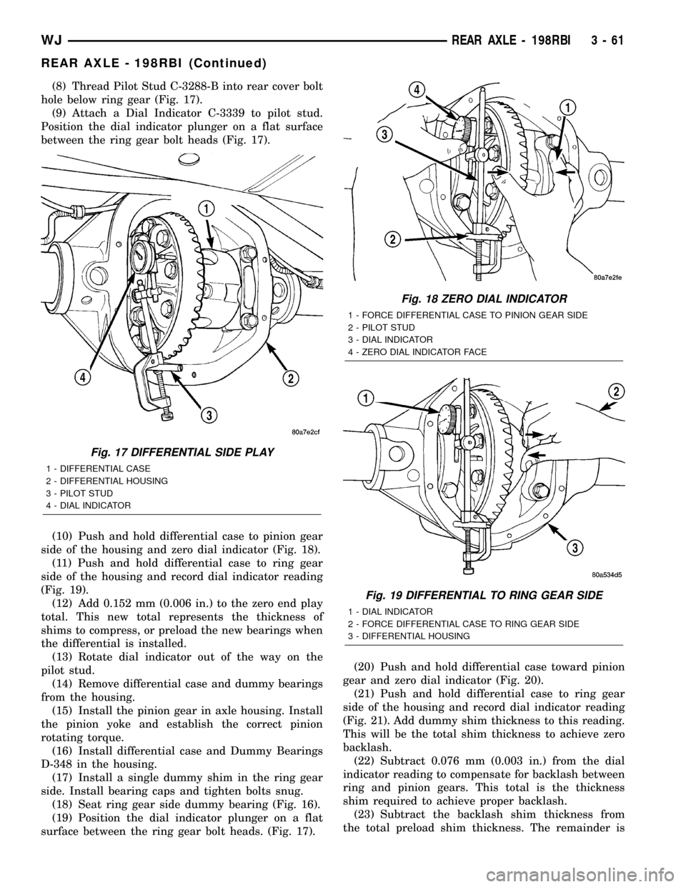
(8) Thread Pilot Stud C-3288-B into rear cover bolt
hole below ring gear (Fig. 17).
(9) Attach a Dial Indicator C-3339 to pilot stud.
Position the dial indicator plunger on a flat surface
between the ring gear bolt heads (Fig. 17).
(10) Push and hold differential case to pinion gear
side of the housing and zero dial indicator (Fig. 18).
(11) Push and hold differential case to ring gear
side of the housing and record dial indicator reading
(Fig. 19).
(12) Add 0.152 mm (0.006 in.) to the zero end play
total. This new total represents the thickness of
shims to compress, or preload the new bearings when
the differential is installed.
(13) Rotate dial indicator out of the way on the
pilot stud.
(14) Remove differential case and dummy bearings
from the housing.
(15) Install the pinion gear in axle housing. Install
the pinion yoke and establish the correct pinion
rotating torque.
(16) Install differential case and Dummy Bearings
D-348 in the housing.
(17) Install a single dummy shim in the ring gear
side. Install bearing caps and tighten bolts snug.
(18) Seat ring gear side dummy bearing (Fig. 16).
(19) Position the dial indicator plunger on a flat
surface between the ring gear bolt heads. (Fig. 17).(20) Push and hold differential case toward pinion
gear and zero dial indicator (Fig. 20).
(21) Push and hold differential case to ring gear
side of the housing and record dial indicator reading
(Fig. 21). Add dummy shim thickness to this reading.
This will be the total shim thickness to achieve zero
backlash.
(22) Subtract 0.076 mm (0.003 in.) from the dial
indicator reading to compensate for backlash between
ring and pinion gears. This total is the thickness
shim required to achieve proper backlash.
(23) Subtract the backlash shim thickness from
the total preload shim thickness. The remainder is
Fig. 17 DIFFERENTIAL SIDE PLAY
1 - DIFFERENTIAL CASE
2 - DIFFERENTIAL HOUSING
3 - PILOT STUD
4 - DIAL INDICATOR
Fig. 18 ZERO DIAL INDICATOR
1 - FORCE DIFFERENTIAL CASE TO PINION GEAR SIDE
2 - PILOT STUD
3 - DIAL INDICATOR
4 - ZERO DIAL INDICATOR FACE
Fig. 19 DIFFERENTIAL TO RING GEAR SIDE
1 - DIAL INDICATOR
2 - FORCE DIFFERENTIAL CASE TO RING GEAR SIDE
3 - DIFFERENTIAL HOUSING
WJREAR AXLE - 198RBI 3 - 61
REAR AXLE - 198RBI (Continued)
Page 108 of 2199
GEAR CONTACT PATTERN
The ring gear and pinion teeth contact patterns
will show if the pinion depth is correct in the hous-
ing. It will also show if the ring gear backlash has
been adjusted correctly. The backlash can be adjusted
within specifications to achieve desired tooth contact
patterns.
(1) Apply a thin coat of hydrated ferric oxide or
equivalent to the drive and coast side of the ring gear
teeth.
(2) Wrap, twist and hold a shop towel around the
pinion yoke to increase the turning resistance of the
pinion. This will provide a more distinct contact pat-
tern.
(3) With a boxed end wrench on a ring gear bolt,
rotate the differential case one complete revolution in
both directions while a load is being applied from
shop towel.
The areas on the ring gear teeth with the greatest
degree of contact against the pinion teeth will squee-
gee the compound to the areas with the least amount
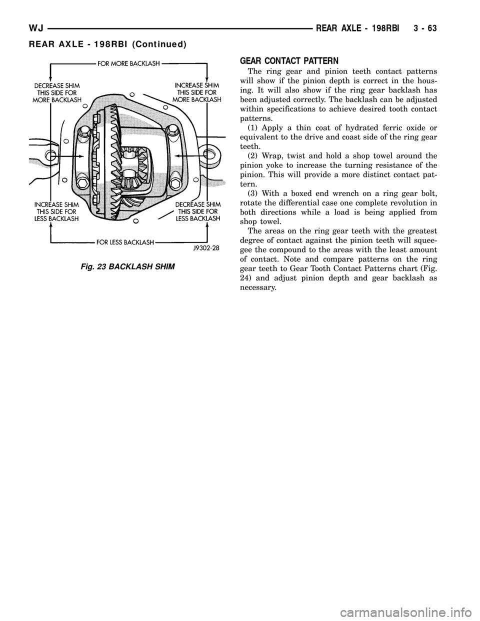
of contact. Note and compare patterns on the ring
gear teeth to Gear Tooth Contact Patterns chart (Fig.
24) and adjust pinion depth and gear backlash as
necessary.
Fig. 23 BACKLASH SHIM
WJREAR AXLE - 198RBI 3 - 63
REAR AXLE - 198RBI (Continued)
Page 134 of 2199
(15) Invert the differential case in the vise.
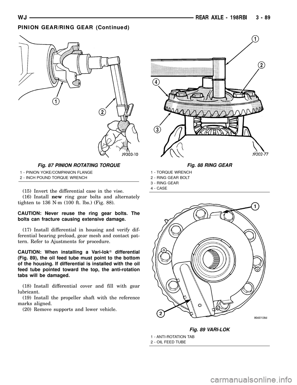
(16) Installnewring gear bolts and alternately
tighten to 136 N´m (100 ft. lbs.) (Fig. 88).
CAUTION: Never reuse the ring gear bolts. The
bolts can fracture causing extensive damage.
(17) Install differential in housing and verify dif-
ferential bearing preload, gear mesh and contact pat-
tern. Refer to Ajustments for procedure.
CAUTION: When installing a Vari-lokTdifferential
(Fig. 89), the oil feed tube must point to the bottom
of the housing. If differential is installed with the oil
feed tube pointed toward the top, the anti-rotation
tabs will be damaged.
(18) Install differential cover and fill with gear
lubricant.
(19) Install the propeller shaft with the reference
marks aligned.
(20) Remove supports and lower vehicle.
Fig. 87 PINION ROTATING TORQUE
1 - PINION YOKE/COMPANION FLANGE
2 - INCH POUND TORQUE WRENCH
Fig. 88 RING GEAR
1 - TORQUE WRENCH
2 - RING GEAR BOLT
3 - RING GEAR
4 - CASE
Fig. 89 VARI-LOK
1 - ANTI-ROTATION TAB
2 - OIL FEED TUBE
WJREAR AXLE - 198RBI 3 - 89
PINION GEAR/RING GEAR (Continued)
Page 147 of 2199
(14) Remove differential case and dummy bearings
from the housing.
(15) Install the pinion gear in the housing. Install
the pinion yoke and establish the correct pinion
rotating torque.
(16) Install differential case and Dummy Bearings
6929-A in the housing.
(17) Install a single dummy shim in the ring gear
side. Install bearing caps and tighten bolts snug.
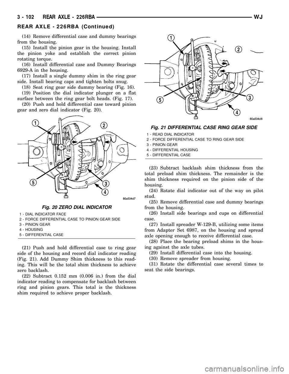
(18) Seat ring gear side dummy bearing (Fig. 16).
(19) Position the dial indicator plunger on a flat
surface between the ring gear bolt heads. (Fig. 17).
(20) Push and hold differential case toward pinion
gear and zero dial indicator (Fig. 20).
(21) Push and hold differential case to ring gear
side of the housing and record dial indicator reading
(Fig. 21). Add Dummy Shim thickness to this read-
ing. This will be the total shim thickness to achieve
zero backlash.
(22) Subtract 0.152 mm (0.006 in.) from the dial
indicator reading to compensate for backlash between
ring and pinion gears. This total is the thickness
shim required to achieve proper backlash.(23) Subtract backlash shim thickness from the
total preload shim thickness. The remainder is the
shim thickness required on the pinion side of the
housing.
(24) Rotate dial indicator out of the way on pilot
stud.
(25) Remove differential case and dummy bearings
from the housing.
(26) Install side bearings and cups on differential
case.
(27) Install spreader W-129-B, utilizing some items
from Adapter Set 6987, on the housing and spread
axle opening enough to receive differential case.
(28) Place the bearing preload shims in the hous-
ing against the axle tubes.
(29) Install differential case into the housing.
(30) Remove spreader from housing.
(31) Rotate the differential case several times to
seat the side bearings.
Fig. 20 ZERO DIAL INDICATOR
1 - DIAL INDICATOR FACE
2 - FORCE DIFFERENTIAL CASE TO PINION GEAR SIDE
3 - PINION GEAR
4 - HOUSING
5 - DIFFERENTIAL CASE
Fig. 21 DIFFERENTIAL CASE RING GEAR SIDE
1 - READ DIAL INDICATOR
2 - FORCE DIFFERENTIAL CASE TO RING GEAR SIDE
3 - PINION GEAR
4 - DIFFERENTIAL HOUSING
5 - DIFFERENTIAL CASE
3 - 102 REAR AXLE - 226RBAWJ
REAR AXLE - 226RBA (Continued)
Page 148 of 2199
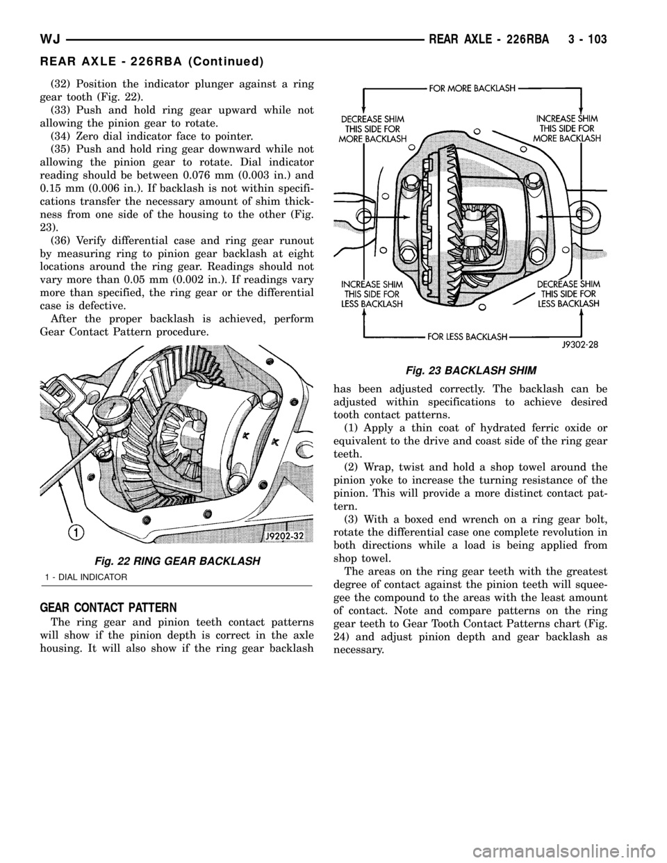
(32) Position the indicator plunger against a ring
gear tooth (Fig. 22).
(33) Push and hold ring gear upward while not
allowing the pinion gear to rotate.
(34) Zero dial indicator face to pointer.
(35) Push and hold ring gear downward while not
allowing the pinion gear to rotate. Dial indicator
reading should be between 0.076 mm (0.003 in.) and
0.15 mm (0.006 in.). If backlash is not within specifi-
cations transfer the necessary amount of shim thick-
ness from one side of the housing to the other (Fig.
23).
(36) Verify differential case and ring gear runout
by measuring ring to pinion gear backlash at eight
locations around the ring gear. Readings should not
vary more than 0.05 mm (0.002 in.). If readings vary
more than specified, the ring gear or the differential
case is defective.
After the proper backlash is achieved, perform
Gear Contact Pattern procedure.
GEAR CONTACT PATTERN
The ring gear and pinion teeth contact patterns
will show if the pinion depth is correct in the axle
housing. It will also show if the ring gear backlashhas been adjusted correctly. The backlash can be
adjusted within specifications to achieve desired
tooth contact patterns.
(1) Apply a thin coat of hydrated ferric oxide or
equivalent to the drive and coast side of the ring gear
teeth.
(2) Wrap, twist and hold a shop towel around the
pinion yoke to increase the turning resistance of the
pinion. This will provide a more distinct contact pat-
tern.
(3) With a boxed end wrench on a ring gear bolt,
rotate the differential case one complete revolution in
both directions while a load is being applied from
shop towel.
The areas on the ring gear teeth with the greatest
degree of contact against the pinion teeth will squee-
gee the compound to the areas with the least amount
of contact. Note and compare patterns on the ring
gear teeth to Gear Tooth Contact Patterns chart (Fig.
24) and adjust pinion depth and gear backlash as
necessary.
Fig. 22 RING GEAR BACKLASH
1 - DIAL INDICATOR
Fig. 23 BACKLASH SHIM
WJREAR AXLE - 226RBA 3 - 103
REAR AXLE - 226RBA (Continued)
Page 174 of 2199
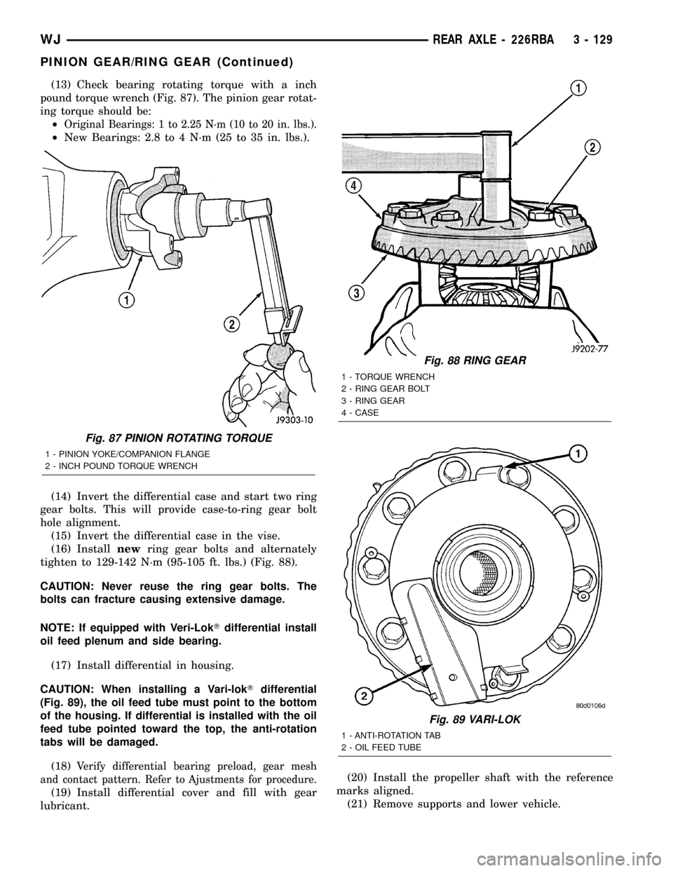
(13) Check bearing rotating torque with a inch
pound torque wrench (Fig. 87). The pinion gear rotat-
ing torque should be:
²
Original Bearings: 1 to 2.25 N´m (10 to 20 in. lbs.).
²New Bearings: 2.8 to 4 N´m (25 to 35 in. lbs.).
(14) Invert the differential case and start two ring
gear bolts. This will provide case-to-ring gear bolt
hole alignment.
(15) Invert the differential case in the vise.
(16) Installnewring gear bolts and alternately
tighten to 129-142 N´m (95-105 ft. lbs.) (Fig. 88).
CAUTION: Never reuse the ring gear bolts. The
bolts can fracture causing extensive damage.
NOTE: If equipped with Veri-LokTdifferential install
oil feed plenum and side bearing.
(17) Install differential in housing.
CAUTION: When installing a Vari-lokTdifferential
(Fig. 89), the oil feed tube must point to the bottom
of the housing. If differential is installed with the oil
feed tube pointed toward the top, the anti-rotation
tabs will be damaged.
(18)
Verify differential bearing preload, gear mesh
and contact pattern. Refer to Ajustments for procedure.
(19) Install differential cover and fill with gear
lubricant.(20) Install the propeller shaft with the reference
marks aligned.
(21) Remove supports and lower vehicle.
Fig. 87 PINION ROTATING TORQUE
1 - PINION YOKE/COMPANION FLANGE
2 - INCH POUND TORQUE WRENCH
Fig. 88 RING GEAR
1 - TORQUE WRENCH
2 - RING GEAR BOLT
3 - RING GEAR
4 - CASE
Fig. 89 VARI-LOK
1 - ANTI-ROTATION TAB
2 - OIL FEED TUBE
WJREAR AXLE - 226RBA 3 - 129
PINION GEAR/RING GEAR (Continued)
Page 192 of 2199
DISASSEMBLY
DISASSEMBLY - FRONT DISC BRAKE CALIPER
(1) Drain the brake fluid from caliper.
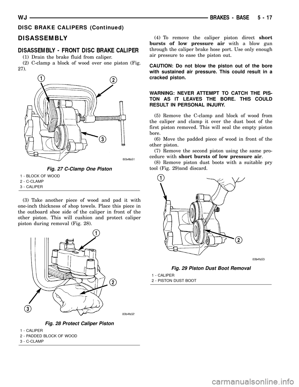
(2) C-clamp a block of wood over one piston (Fig.
27).
(3) Take another piece of wood and pad it with
one-inch thickness of shop towels. Place this piece in
the outboard shoe side of the caliper in front of the
other piston. This will cushion and protect caliper
piston during removal (Fig. 28).(4) To remove the caliper piston directshort
bursts of low pressure airwith a blow gun
through the caliper brake hose port. Use only enough
air pressure to ease the piston out.
CAUTION: Do not blow the piston out of the bore
with sustained air pressure. This could result in a
cracked piston.
WARNING: NEVER ATTEMPT TO CATCH THE PIS-
TON AS IT LEAVES THE BORE. THIS COULD
RESULT IN PERSONAL INJURY.
(5) Remove the C-clamp and block of wood from
the caliper and clamp it over the dust boot of the
first piston removed. This will seal the empty piston
bore.
(6) Move the padded piece of wood in front of the
other piston.
(7) Remove the second piston using the same pro-
cedure withshort bursts of low pressure air.
(8) Remove piston dust boots with a suitable pry
tool (Fig. 29)and discard.
Fig. 27 C-Clamp One Piston
1 - BLOCK OF WOOD
2 - C-CLAMP
3 - CALIPER
Fig. 28 Protect Caliper Piston
1 - CALIPER
2 - PADDED BLOCK OF WOOD
3 - C-CLAMP
Fig. 29 Piston Dust Boot Removal
1 - CALIPER
2 - PISTON DUST BOOT
WJBRAKES - BASE 5 - 17
DISC BRAKE CALIPERS (Continued)
Page 193 of 2199
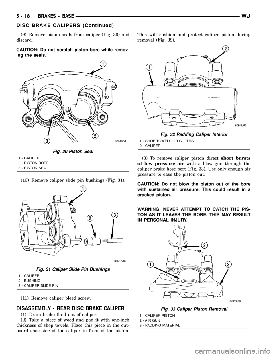
(9) Remove piston seals from caliper (Fig. 30) and
discard.
CAUTION: Do not scratch piston bore while remov-
ing the seals.
(10) Remove caliper slide pin bushings (Fig. 31).
(11) Remove caliper bleed screw.
DISASSEMBLY - REAR DISC BRAKE CALIPER
(1) Drain brake fluid out of caliper.
(2) Take a piece of wood and pad it with one-inch
thickness of shop towels. Place this piece in the out-
board shoe side of the caliper in front of the piston.This will cushion and protect caliper piston during
removal (Fig. 32).
(3) To remove caliper piston directshort bursts
of low pressure airwith a blow gun through the
caliper brake hose port (Fig. 33). Use only enough air
pressure to ease the piston out.
CAUTION: Do not blow the piston out of the bore
with sustained air pressure. This could result in a
cracked piston.
WARNING: NEVER ATTEMPT TO CATCH THE PIS-
TON AS IT LEAVES THE BORE. THIS MAY RESULT
IN PERSONAL INJURY.
Fig. 30 Piston Seal
1 - CALIPER
2 - PISTON BORE
3 - PISTON SEAL
Fig. 31 Caliper Slide Pin Bushings
1 - CALIPER
2 - BUSHING
3 - CALIPER SLIDE PIN
Fig. 32 Padding Caliper Interior
1 - SHOP TOWELS OR CLOTHS
2 - CALIPER
Fig. 33 Caliper Piston Removal
1 - CALIPER PISTON
2 - AIR GUN
3 - PADDING MATERIAL
5 - 18 BRAKES - BASEWJ
DISC BRAKE CALIPERS (Continued)
Page 194 of 2199
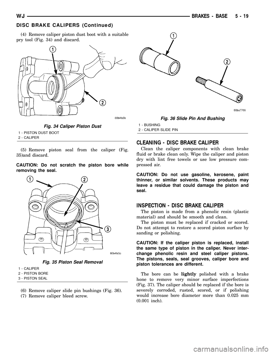
(4) Remove caliper piston dust boot with a suitable
pry tool (Fig. 34) and discard.
(5) Remove piston seal from the caliper (Fig.
35)and discard.
CAUTION: Do not scratch the piston bore while
removing the seal.
(6) Remove caliper slide pin bushings (Fig. 36).
(7) Remove caliper bleed screw.
CLEANING - DISC BRAKE CALIPER
Clean the caliper components with clean brake
fluid or brake clean only. Wipe the caliper and piston
dry with lint free towels or use low pressure com-
pressed air.
CAUTION: Do not use gasoline, kerosene, paint
thinner, or similar solvents. These products may
leave a residue that could damage the piston and
seal.
INSPECTION - DISC BRAKE CALIPER
The piston is made from a phenolic resin (plastic
material) and should be smooth and clean.
The piston must be replaced if cracked or scored.
Do not attempt to restore a scored piston surface by
sanding or polishing.
CAUTION: If the caliper piston is replaced, install
the same type of piston in the caliper. Never inter-
change phenolic resin and steel caliper pistons.
The pistons, seals, seal grooves, caliper bore and
piston tolerances are different.
The bore can belightlypolished with a brake
hone to remove very minor surface imperfections
(Fig. 37). The caliper should be replaced if the bore is
severely corroded, rusted, scored, or if polishing
would increase bore diameter more than 0.025 mm
(0.001 inch).
Fig. 34 Caliper Piston Dust
1 - PISTON DUST BOOT
2 - CALIPER
Fig. 35 Piston Seal Removal
1 - CALIPER
2 - PISTON BORE
3 - PISTON SEAL
Fig. 36 Slide Pin And Bushing
1 - BUSHING
2 - CALIPER SLIDE PIN
WJBRAKES - BASE 5 - 19
DISC BRAKE CALIPERS (Continued)
Page 219 of 2199
G-SWITCH
DESCRIPTION
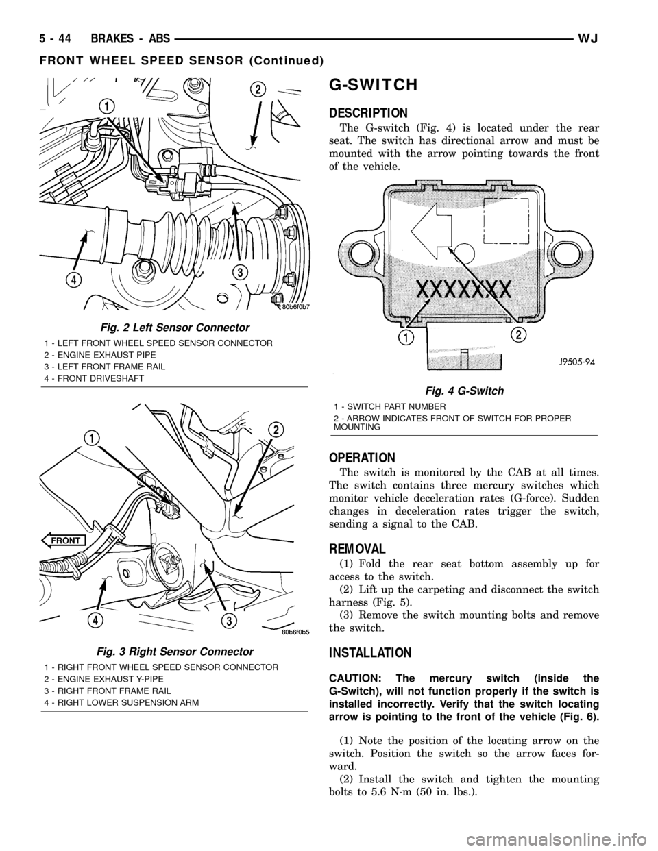
The G-switch (Fig. 4) is located under the rear
seat. The switch has directional arrow and must be
mounted with the arrow pointing towards the front
of the vehicle.
OPERATION
The switch is monitored by the CAB at all times.
The switch contains three mercury switches which
monitor vehicle deceleration rates (G-force). Sudden
changes in deceleration rates trigger the switch,
sending a signal to the CAB.
REMOVAL
(1) Fold the rear seat bottom assembly up for
access to the switch.
(2) Lift up the carpeting and disconnect the switch
harness (Fig. 5).
(3) Remove the switch mounting bolts and remove
the switch.
INSTALLATION
CAUTION: The mercury switch (inside the
G-Switch), will not function properly if the switch is
installed incorrectly. Verify that the switch locating
arrow is pointing to the front of the vehicle (Fig. 6).
(1) Note the position of the locating arrow on the
switch. Position the switch so the arrow faces for-
ward.
(2) Install the switch and tighten the mounting
bolts to 5.6 N´m (50 in. lbs.).
Fig. 2 Left Sensor Connector
1 - LEFT FRONT WHEEL SPEED SENSOR CONNECTOR
2 - ENGINE EXHAUST PIPE
3 - LEFT FRONT FRAME RAIL
4 - FRONT DRIVESHAFT
Fig. 3 Right Sensor Connector
1 - RIGHT FRONT WHEEL SPEED SENSOR CONNECTOR
2 - ENGINE EXHAUST Y-PIPE
3 - RIGHT FRONT FRAME RAIL
4 - RIGHT LOWER SUSPENSION ARM
Fig. 4 G-Switch
1 - SWITCH PART NUMBER
2 - ARROW INDICATES FRONT OF SWITCH FOR PROPER
MOUNTING
5 - 44 BRAKES - ABSWJ
FRONT WHEEL SPEED SENSOR (Continued)