wheel alignment JEEP GRAND CHEROKEE 2002 WJ / 2.G User Guide
[x] Cancel search | Manufacturer: JEEP, Model Year: 2002, Model line: GRAND CHEROKEE, Model: JEEP GRAND CHEROKEE 2002 WJ / 2.GPages: 2199, PDF Size: 76.01 MB
Page 98 of 2199
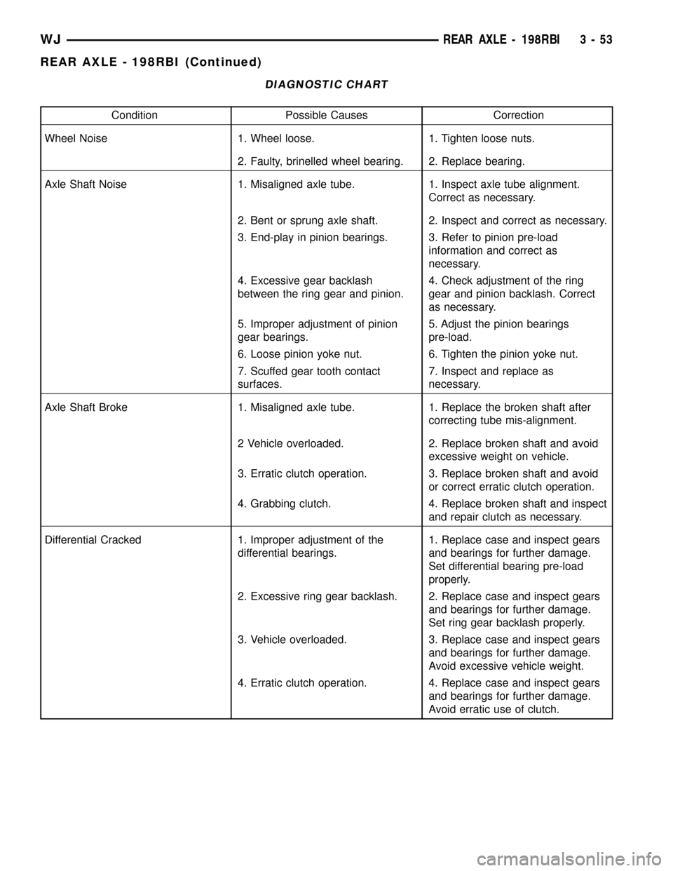
DIAGNOSTIC CHART
Condition Possible Causes Correction
Wheel Noise 1. Wheel loose. 1. Tighten loose nuts.
2. Faulty, brinelled wheel bearing. 2. Replace bearing.
Axle Shaft Noise 1. Misaligned axle tube. 1. Inspect axle tube alignment.
Correct as necessary.
2. Bent or sprung axle shaft. 2. Inspect and correct as necessary.
3. End-play in pinion bearings. 3. Refer to pinion pre-load
information and correct as
necessary.
4. Excessive gear backlash
between the ring gear and pinion.4. Check adjustment of the ring
gear and pinion backlash. Correct
as necessary.
5. Improper adjustment of pinion
gear bearings.5. Adjust the pinion bearings
pre-load.
6. Loose pinion yoke nut. 6. Tighten the pinion yoke nut.
7. Scuffed gear tooth contact
surfaces.7. Inspect and replace as
necessary.
Axle Shaft Broke 1. Misaligned axle tube. 1. Replace the broken shaft after
correcting tube mis-alignment.
2 Vehicle overloaded. 2. Replace broken shaft and avoid
excessive weight on vehicle.
3. Erratic clutch operation. 3. Replace broken shaft and avoid
or correct erratic clutch operation.
4. Grabbing clutch. 4. Replace broken shaft and inspect
and repair clutch as necessary.
Differential Cracked 1. Improper adjustment of the
differential bearings.1. Replace case and inspect gears
and bearings for further damage.
Set differential bearing pre-load
properly.
2. Excessive ring gear backlash. 2. Replace case and inspect gears
and bearings for further damage.
Set ring gear backlash properly.
3. Vehicle overloaded. 3. Replace case and inspect gears
and bearings for further damage.
Avoid excessive vehicle weight.
4. Erratic clutch operation. 4. Replace case and inspect gears
and bearings for further damage.
Avoid erratic use of clutch.
WJREAR AXLE - 198RBI 3 - 53
REAR AXLE - 198RBI (Continued)
Page 138 of 2199
DRIVELINE SNAP
A snap or clunk noise when the vehicle is shifted
into gear (or the clutch engaged), can be caused by:
²High engine idle speed.
²Transmission shift operation.
²Loose engine/transmission/transfer case mounts.
²Worn U-joints.
²Loose spring mounts.
²Loose pinion gear nut and yoke.²Excessive ring gear backlash.
²Excessive side gear to case clearance.
The source of a snap or a clunk noise can be deter-
mined with the assistance of a helper. Raise the vehi-
cle on a hoist with the wheels free to rotate. Instruct
the helper to shift the transmission into gear. Listen
for the noise, a mechanics stethoscope is helpful in
isolating the source of a noise.
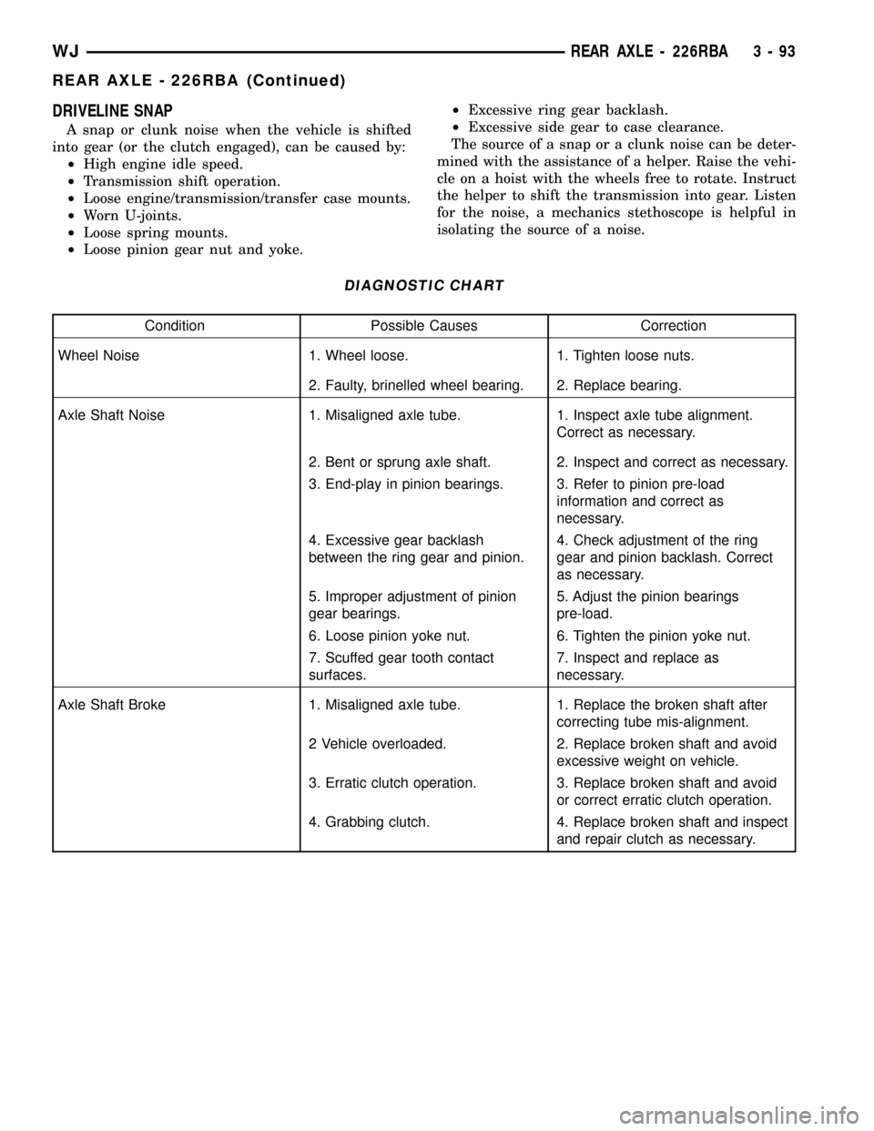
DIAGNOSTIC CHART
Condition Possible Causes Correction
Wheel Noise 1. Wheel loose. 1. Tighten loose nuts.
2. Faulty, brinelled wheel bearing. 2. Replace bearing.
Axle Shaft Noise 1. Misaligned axle tube. 1. Inspect axle tube alignment.
Correct as necessary.
2. Bent or sprung axle shaft. 2. Inspect and correct as necessary.
3. End-play in pinion bearings. 3. Refer to pinion pre-load
information and correct as
necessary.
4. Excessive gear backlash
between the ring gear and pinion.4. Check adjustment of the ring
gear and pinion backlash. Correct
as necessary.
5. Improper adjustment of pinion
gear bearings.5. Adjust the pinion bearings
pre-load.
6. Loose pinion yoke nut. 6. Tighten the pinion yoke nut.
7. Scuffed gear tooth contact
surfaces.7. Inspect and replace as
necessary.
Axle Shaft Broke 1. Misaligned axle tube. 1. Replace the broken shaft after
correcting tube mis-alignment.
2 Vehicle overloaded. 2. Replace broken shaft and avoid
excessive weight on vehicle.
3. Erratic clutch operation. 3. Replace broken shaft and avoid
or correct erratic clutch operation.
4. Grabbing clutch. 4. Replace broken shaft and inspect
and repair clutch as necessary.
WJREAR AXLE - 226RBA 3 - 93
REAR AXLE - 226RBA (Continued)
Page 179 of 2199
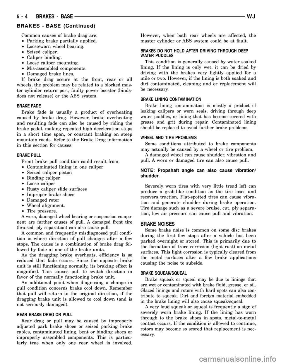
Common causes of brake drag are:
²Parking brake partially applied.
²Loose/worn wheel bearing.
²Seized caliper.
²Caliper binding.
²Loose caliper mounting.
²Mis-assembled components.
²Damaged brake lines.
If brake drag occurs at the front, rear or all
wheels, the problem may be related to a blocked mas-
ter cylinder return port, faulty power booster (binds-
does not release) or the ABS system.
BRAKE FADE
Brake fade is usually a product of overheating
caused by brake drag. However, brake overheating
and resulting fade can also be caused by riding the
brake pedal, making repeated high deceleration stops
in a short time span, or constant braking on steep
mountain roads. Refer to the Brake Drag information
in this section for causes.
BRAKE PULL
Front brake pull condition could result from:
²Contaminated lining in one caliper
²Seized caliper piston
²Binding caliper
²Loose caliper
²Rusty caliper slide surfaces
²Improper brake shoes
²Damaged rotor
²Wheel alignment.
²Tire pressure.
A worn, damaged wheel bearing or suspension compo-
nent are further causes of pull. A damaged front tire
(bruised, ply separation) can also cause pull.
A common and frequently misdiagnosed pull condi-
tion is where direction of pull changes after a few
stops. The cause is a combination of brake drag fol-
lowed by fade at one of the brake units.
As the dragging brake overheats, efficiency is so
reduced that fade occurs. Since the opposite brake
unit is still functioning normally, its braking effect is
magnified. This causes pull to switch direction in
favor of the normally functioning brake unit.
An additional point when diagnosing a change in
pull condition concerns brake cool down. Remember
that pull will return to the original direction, if the
dragging brake unit is allowed to cool down (and is
not seriously damaged).
REAR BRAKE DRAG OR PULL
Rear drag or pull may be caused by improperly
adjusted park brake shoes or seized parking brake
cables, contaminated lining, bent or binding shoes or
improperly assembled components. This is particu-
larly true when only one rear wheel is involved.However, when both rear wheels are affected, the
master cylinder or ABS system could be at fault.
BRAKES DO NOT HOLD AFTER DRIVING THROUGH DEEP
WATER PUDDLES
This condition is generally caused by water soaked
lining. If the lining is only wet, it can be dried by
driving with the brakes very lightly applied for a
mile or two. However, if the lining is both soaked and
dirt contaminated, cleaning and or replacement will
be necessary.
BRAKE LINING CONTAMINATION
Brake lining contamination is mostly a product of
leaking calipers or worn seals, driving through deep
water puddles, or lining that has become covered with
grease and grit during repair. Contaminated lining
should be replaced to avoid further brake problems.
WHEEL AND TIRE PROBLEMS
Some conditions attributed to brake components
may actually be caused by a wheel or tire problem.
A damaged wheel can cause shudder, vibration and
pull. A worn or damaged tire can also cause pull.
NOTE: Propshaft angle can also cause vibration/
shudder.
Severely worn tires with very little tread left can
produce a grab-like condition as the tire loses and
recovers traction. Flat-spotted tires can cause vibra-
tion and generate shudder during brake operation.
Tire damage such as a severe bruise, cut, ply separa-
tion, low air pressure can cause pull and vibration.
BRAKE NOISES
Some brake noise is common on some disc brakes
during the first few stops after a vehicle has been
parked overnight or stored. This is primarily due to
the formation of trace corrosion (light rust) on metal
surfaces. This light corrosion is typically cleared from
the metal surfaces after a few brake applications
causing the noise to subside.
BRAKE SQUEAK/SQUEAL
Brake squeak or squeal may be due to linings that
are wet or contaminated with brake fluid, grease, or oil.
Glazed linings and rotors with hard spots can also con-
tribute to squeak. Dirt and foreign material embedded
in the brake lining will also cause squeak/squeal.
A very loud squeak or squeal is frequently a sign of
severely worn brake lining. If the lining has worn
through to the brake shoes in spots, metal-to-metal
contact occurs. If the condition is allowed to continue,
rotors may become so scored that replacement is nec-
essary.
5 - 4 BRAKES - BASEWJ
BRAKES - BASE (Continued)
Page 475 of 2199
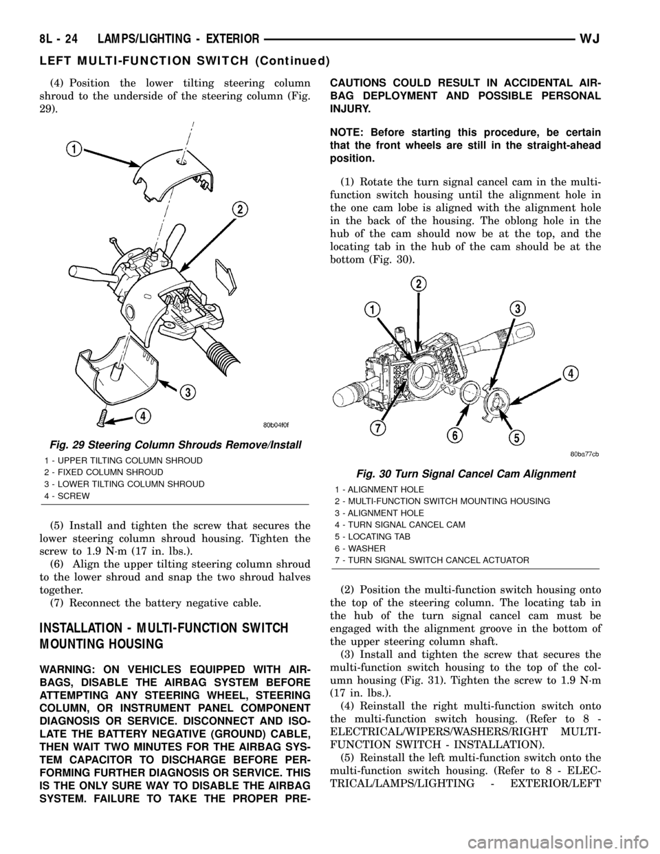
(4) Position the lower tilting steering column
shroud to the underside of the steering column (Fig.
29).
(5) Install and tighten the screw that secures the
lower steering column shroud housing. Tighten the
screw to 1.9 N´m (17 in. lbs.).
(6) Align the upper tilting steering column shroud
to the lower shroud and snap the two shroud halves
together.
(7) Reconnect the battery negative cable.
INSTALLATION - MULTI-FUNCTION SWITCH
MOUNTING HOUSING
WARNING: ON VEHICLES EQUIPPED WITH AIR-
BAGS, DISABLE THE AIRBAG SYSTEM BEFORE
ATTEMPTING ANY STEERING WHEEL, STEERING
COLUMN, OR INSTRUMENT PANEL COMPONENT
DIAGNOSIS OR SERVICE. DISCONNECT AND ISO-
LATE THE BATTERY NEGATIVE (GROUND) CABLE,
THEN WAIT TWO MINUTES FOR THE AIRBAG SYS-
TEM CAPACITOR TO DISCHARGE BEFORE PER-
FORMING FURTHER DIAGNOSIS OR SERVICE. THIS
IS THE ONLY SURE WAY TO DISABLE THE AIRBAG
SYSTEM. FAILURE TO TAKE THE PROPER PRE-CAUTIONS COULD RESULT IN ACCIDENTAL AIR-
BAG DEPLOYMENT AND POSSIBLE PERSONAL
INJURY.
NOTE: Before starting this procedure, be certain
that the front wheels are still in the straight-ahead
position.
(1) Rotate the turn signal cancel cam in the multi-
function switch housing until the alignment hole in
the one cam lobe is aligned with the alignment hole
in the back of the housing. The oblong hole in the
hub of the cam should now be at the top, and the
locating tab in the hub of the cam should be at the
bottom (Fig. 30).
(2) Position the multi-function switch housing onto
the top of the steering column. The locating tab in
the hub of the turn signal cancel cam must be
engaged with the alignment groove in the bottom of
the upper steering column shaft.
(3) Install and tighten the screw that secures the
multi-function switch housing to the top of the col-
umn housing (Fig. 31). Tighten the screw to 1.9 N´m
(17 in. lbs.).
(4) Reinstall the right multi-function switch onto
the multi-function switch housing. (Refer to 8 -
ELECTRICAL/WIPERS/WASHERS/RIGHT MULTI-
FUNCTION SWITCH - INSTALLATION).
(5) Reinstall the left multi-function switch onto the
multi-function switch housing. (Refer to 8 - ELEC-
TRICAL/LAMPS/LIGHTING - EXTERIOR/LEFT
Fig. 29 Steering Column Shrouds Remove/Install
1 - UPPER TILTING COLUMN SHROUD
2 - FIXED COLUMN SHROUD
3 - LOWER TILTING COLUMN SHROUD
4 - SCREW
Fig. 30 Turn Signal Cancel Cam Alignment
1 - ALIGNMENT HOLE
2 - MULTI-FUNCTION SWITCH MOUNTING HOUSING
3 - ALIGNMENT HOLE
4 - TURN SIGNAL CANCEL CAM
5 - LOCATING TAB
6 - WASHER
7 - TURN SIGNAL SWITCH CANCEL ACTUATOR
8L - 24 LAMPS/LIGHTING - EXTERIORWJ
LEFT MULTI-FUNCTION SWITCH (Continued)
Page 477 of 2199
INSTALLATION
INSTALLATION - BULBS
(1) Position the bulb in socket and push into place.
(2) Position the bulb socket in the lamp and rotate
clockwise.
(3) Install the lamp.
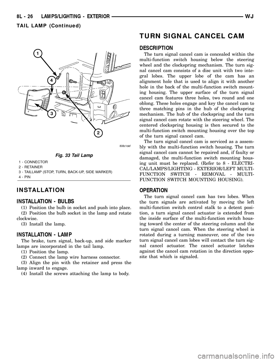
INSTALLATION - LAMP
The brake, turn signal, back-up, and side marker
lamps are incorporated in the tail lamp.
(1) Position the lamp.
(2) Connect the lamp wire harness connector.
(3) Align the pin with the retainer and press the
lamp inward to engage.
(4) Install the screws attaching the lamp to body.
TURN SIGNAL CANCEL CAM
DESCRIPTION
The turn signal cancel cam is concealed within the
multi-function switch housing below the steering
wheel and the clockspring mechanism. The turn sig-
nal cancel cam consists of a disc unit with two inte-
gral lobes. The upper lobe of the cam has an
alignment hole that is used to align it with another
hole in the back of the multi-function switch mount-
ing housing. The upper surface of the turn signal
cancel cam features three holes, two round and one
oblong. These holes engage and key the cancel cam to
three matching pins in the hub of the clockspring
mechanism. The hub of the clockspring and the turn
signal cancel cam rotate with the steering wheel. The
centered clockspring housing is then secured to the
multi-function switch mounting housing over the top
of the turn signal cancel cam.
The turn signal cancel cam is serviced as a assem-
bly with the multi-function switch housing. The turn
signal cancel cam cannot be repaired and, if faulty or
damaged, the multi-function switch mounting hous-
ing unit must be replaced. (Refer to 8 - ELECTRI-
CAL/LAMPS/LIGHTING - EXTERIOR/LEFT MULTI-
FUNCTION SWITCH - REMOVAL - MULTI-
FUNCTION SWITCH MOUNTING HOUSING).
OPERATION
The turn signal cancel cam has two lobes. When
the turn signals are activated by moving the left
multi-function switch control stalk to a detent posi-
tion, a turn signal cancel actuator is extended from
the inside surface of the multi-function switch hous-
ing toward the center of the steering column and the
turn signal cancel cam. When the steering wheel is
rotated during a turning maneuver, one of the two
turn signal cancel cam lobes will contact the turn sig-
nal cancel actuator. The cancel actuator latches
against the cancel cam rotation in the direction oppo-
site that which is signaled.
Fig. 33 Tail Lamp
1 - CONNECTOR
2 - RETAINER
3 - TAILLAMP (STOP, TURN, BACK-UP, SIDE MARKER)
4 - PIN
8L - 26 LAMPS/LIGHTING - EXTERIORWJ
TAIL LAMP (Continued)
Page 551 of 2199
INSTALLATION
The following service procedure applies to vehicles
manufactured for sale in North America, which have
removable child seat tether anchor brackets that are
located on the inner liftgate opening header. Vehicles
manufactured for sale in Rest-Of-World (ROW) mar-
kets have child tether anchors that are integral to,
and are only serviced with the rear seat back panels.
(1) Position the child tether anchor bracket onto
the inner liftgate opening header (Fig. 12).
(2) Install and tighten the screw that secures the
child tether anchor bracket to the inner liftgate open-
ing header. Tighten the screw to 11.8 N´m (105 in.
lbs.).
(3) Reinstall the cover into the child tether anchor
bezel in the headliner near the liftgate opening
header.
CLOCKSPRING
DESCRIPTION
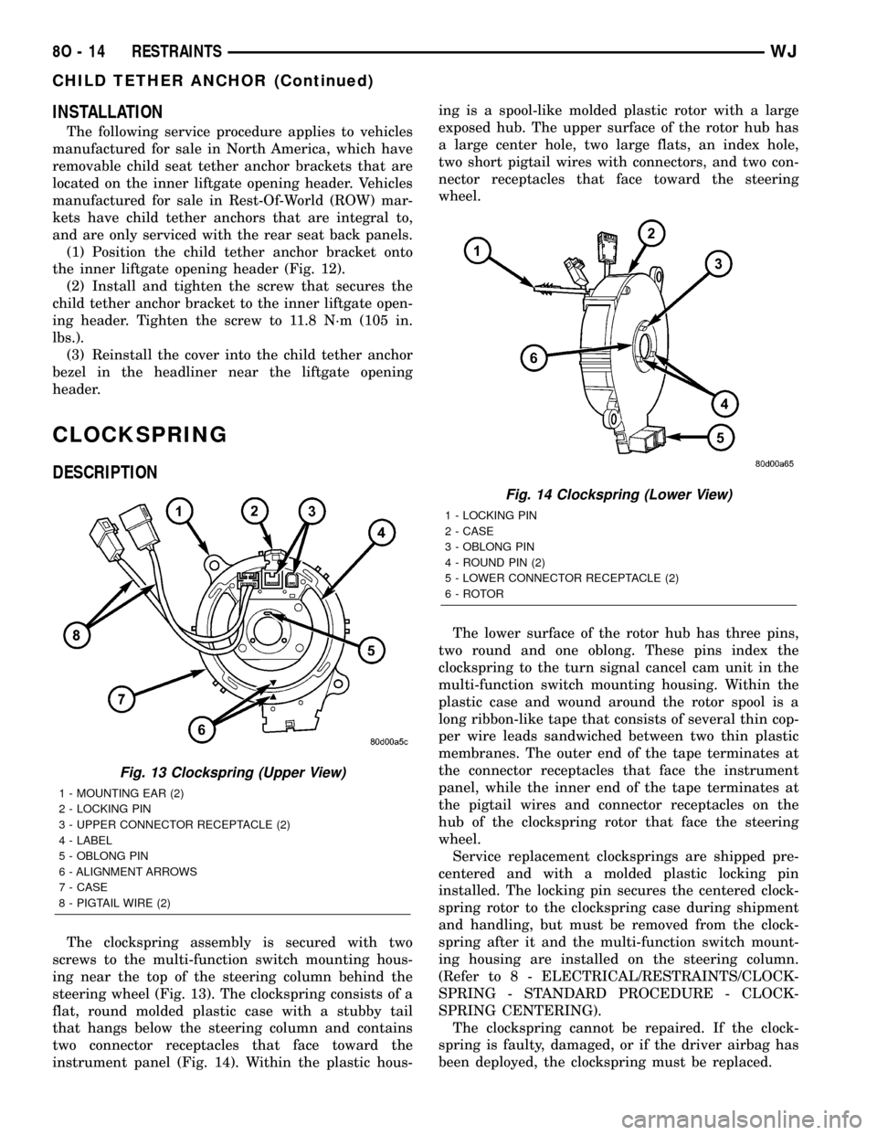
The clockspring assembly is secured with two
screws to the multi-function switch mounting hous-
ing near the top of the steering column behind the
steering wheel (Fig. 13). The clockspring consists of a
flat, round molded plastic case with a stubby tail
that hangs below the steering column and contains
two connector receptacles that face toward the
instrument panel (Fig. 14). Within the plastic hous-ing is a spool-like molded plastic rotor with a large
exposed hub. The upper surface of the rotor hub has
a large center hole, two large flats, an index hole,
two short pigtail wires with connectors, and two con-
nector receptacles that face toward the steering
wheel.
The lower surface of the rotor hub has three pins,
two round and one oblong. These pins index the
clockspring to the turn signal cancel cam unit in the
multi-function switch mounting housing. Within the
plastic case and wound around the rotor spool is a
long ribbon-like tape that consists of several thin cop-
per wire leads sandwiched between two thin plastic
membranes. The outer end of the tape terminates at
the connector receptacles that face the instrument
panel, while the inner end of the tape terminates at
the pigtail wires and connector receptacles on the
hub of the clockspring rotor that face the steering
wheel.
Service replacement clocksprings are shipped pre-
centered and with a molded plastic locking pin
installed. The locking pin secures the centered clock-
spring rotor to the clockspring case during shipment
and handling, but must be removed from the clock-
spring after it and the multi-function switch mount-
ing housing are installed on the steering column.
(Refer to 8 - ELECTRICAL/RESTRAINTS/CLOCK-
SPRING - STANDARD PROCEDURE - CLOCK-
SPRING CENTERING).
The clockspring cannot be repaired. If the clock-
spring is faulty, damaged, or if the driver airbag has
been deployed, the clockspring must be replaced.
Fig. 13 Clockspring (Upper View)
1 - MOUNTING EAR (2)
2 - LOCKING PIN
3 - UPPER CONNECTOR RECEPTACLE (2)
4 - LABEL
5 - OBLONG PIN
6 - ALIGNMENT ARROWS
7 - CASE
8 - PIGTAIL WIRE (2)
Fig. 14 Clockspring (Lower View)
1 - LOCKING PIN
2 - CASE
3 - OBLONG PIN
4 - ROUND PIN (2)
5 - LOWER CONNECTOR RECEPTACLE (2)
6 - ROTOR
8O - 14 RESTRAINTSWJ
CHILD TETHER ANCHOR (Continued)
Page 553 of 2199
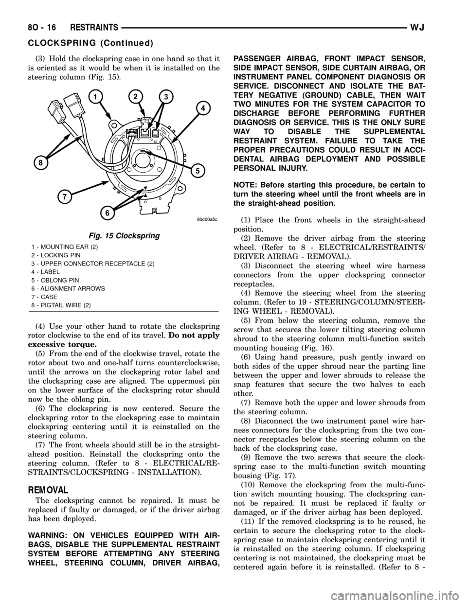
(3) Hold the clockspring case in one hand so that it
is oriented as it would be when it is installed on the
steering column (Fig. 15).
(4) Use your other hand to rotate the clockspring
rotor clockwise to the end of its travel.Do not apply
excessive torque.
(5) From the end of the clockwise travel, rotate the
rotor about two and one-half turns counterclockwise,
until the arrows on the clockspring rotor label and
the clockspring case are aligned. The uppermost pin
on the lower surface of the clockspring rotor should
now be the oblong pin.
(6) The clockspring is now centered. Secure the
clockspring rotor to the clockspring case to maintain
clockspring centering until it is reinstalled on the
steering column.
(7) The front wheels should still be in the straight-
ahead position. Reinstall the clockspring onto the
steering column. (Refer to 8 - ELECTRICAL/RE-
STRAINTS/CLOCKSPRING - INSTALLATION).
REMOVAL
The clockspring cannot be repaired. It must be
replaced if faulty or damaged, or if the driver airbag
has been deployed.
WARNING: ON VEHICLES EQUIPPED WITH AIR-
BAGS, DISABLE THE SUPPLEMENTAL RESTRAINT
SYSTEM BEFORE ATTEMPTING ANY STEERING
WHEEL, STEERING COLUMN, DRIVER AIRBAG,PASSENGER AIRBAG, FRONT IMPACT SENSOR,
SIDE IMPACT SENSOR, SIDE CURTAIN AIRBAG, OR
INSTRUMENT PANEL COMPONENT DIAGNOSIS OR
SERVICE. DISCONNECT AND ISOLATE THE BAT-
TERY NEGATIVE (GROUND) CABLE, THEN WAIT
TWO MINUTES FOR THE SYSTEM CAPACITOR TO
DISCHARGE BEFORE PERFORMING FURTHER
DIAGNOSIS OR SERVICE. THIS IS THE ONLY SURE
WAY TO DISABLE THE SUPPLEMENTAL
RESTRAINT SYSTEM. FAILURE TO TAKE THE
PROPER PRECAUTIONS COULD RESULT IN ACCI-
DENTAL AIRBAG DEPLOYMENT AND POSSIBLE
PERSONAL INJURY.
NOTE: Before starting this procedure, be certain to
turn the steering wheel until the front wheels are in
the straight-ahead position.
(1) Place the front wheels in the straight-ahead
position.
(2) Remove the driver airbag from the steering
wheel. (Refer to 8 - ELECTRICAL/RESTRAINTS/
DRIVER AIRBAG - REMOVAL).
(3) Disconnect the steering wheel wire harness
connectors from the upper clockspring connector
receptacles.
(4) Remove the steering wheel from the steering
column. (Refer to 19 - STEERING/COLUMN/STEER-
ING WHEEL - REMOVAL).
(5) From below the steering column, remove the
screw that secures the lower tilting steering column
shroud to the steering column multi-function switch
mounting housing (Fig. 16).
(6) Using hand pressure, push gently inward on
both sides of the upper shroud near the parting line
between the upper and lower shrouds to release the
snap features that secure the two halves to each
other.
(7) Remove both the upper and lower shrouds from
the steering column.
(8) Disconnect the two instrument panel wire har-
ness connectors for the clockspring from the two con-
nector receptacles below the steering column on the
back of the clockspring case.
(9) Remove the two screws that secure the clock-
spring case to the multi-function switch mounting
housing (Fig. 17).
(10) Remove the clockspring from the multi-func-
tion switch mounting housing. The clockspring can-
not be repaired. It must be replaced if faulty or
damaged, or if the driver airbag has been deployed.
(11) If the removed clockspring is to be reused, be
certain to secure the clockspring rotor to the clock-
spring case to maintain clockspring centering until it
is reinstalled on the steering column. If clockspring
centering is not maintained, the clockspring must be
centered again before it is reinstalled. (Refer to 8 -
Fig. 15 Clockspring
1 - MOUNTING EAR (2)
2 - LOCKING PIN
3 - UPPER CONNECTOR RECEPTACLE (2)
4 - LABEL
5 - OBLONG PIN
6 - ALIGNMENT ARROWS
7 - CASE
8 - PIGTAIL WIRE (2)
8O - 16 RESTRAINTSWJ
CLOCKSPRING (Continued)
Page 1256 of 2199

INSTALLATION
CAUTION: When installing the engine into a vehicle
equipped with an automatic transmission, be care-
ful not to damage the trigger wheel on the engine
flywheel.
(1) Attach a lifting device to the engine and lower
the engine into the engine compartment. For easier
installation, it may be necessary to remove the
engine mount bracket as an aid in alignment of the
engine to the transmission.
(2) Align the transmission torque converter hous-
ing with the engine.
(3) Loosely install the converter housing lower
bolts and install the next higher bolt and nut on each
side.
(4) Tighten all 4 bolts finger tight.
(5) Install the engine mount brackets (if removed).
(6) Lower the engine and engine mount brackets
onto the engine compartment cushions. Install the
bolts and finger tighten the nuts.
(7) Remove the engine lifting device.
(8) Raise and support the vehicle.
(9) Install the remaining engine flywheel/converter
housing bolts. Tighten all bolts to 38 N´m (28 ft. lbs.)
torque.
(10) Install the converter-to-drive plate bolts.
(11) Ensure the installation reference marks are
aligned.
(12) Install the engine flywheel/converter housing
access cover.
(13) Install the exhaust pipe support and tighten
the screw.
(14) Install the engine bending brace (Refer to 9 -
ENGINE/ENGINE BLOCK/STRUCT SUPPORT -
INSTALLATION).
(15) Tighten the engine mount-to-bracket bolts.
(16) Connect the vehicle speed sensor wire connec-
tions and tighten the screws.
(17) Connect the exhaust pipe to the manifold.
(18) Install the engine starter motor (Refer to 8 -
ELECTRICAL/STARTING/STARTER MOTOR -
INSTALLATION).
(19) Connect the wires to the engine starter motor
solenoid.
(20) Lower the vehicle.
(21) Connect all the vacuum hoses and wire con-
nectors identified during engine removal.
(22) Remove protective caps from the power steer-
ing hoses.
(23) Connect the hoses to the fittings at the steer-
ing gear. Tighten the nut to 52 N´m (38 ft. lbs.)
torque.
(24) Fill the pump reservoir with fluid.(25) Inspect the fuel supply line o-ring(s) and
replace if necessary. Connect fuel supply line to injec-
tior rail and verify connection by pulling outward on
the line.
(26) Install the fuel line bracket to the intake
manifold.
(27) Connect the coil rail electrical connectors and
oil pressure switch connector.
(28) Connect the following electrical connectors:
²Power steering pressure switch
²Coolant temperature sensor
²Six (6) fuel injector connectors
²Intake air temperature sensor
²Throttle position sensor
²Map sensor
²Crankshaft position sensor
²Oxygen sensor
²Camshaft position sensor
²Generator connector and B+ terminal wire
(29) Connect all previously removed vacuum hoses.
(30) Connect the body ground strap.
(31) Install the throttle, transmission line pres-
sure, and speed control cables to their mounting
bracket and connect them to the throttle body.
(32) Connect the heater hoses at the engine ther-
mostat housing and water pump.
(33) Install the fan assembly (Refer to 7 - COOL-
ING/ENGINE/RADIATOR FAN - INSTALLATION).
(34) Place the fan shroud in position over the fan.
(35) Install the radiator (Refer to 7 - COOLING/
ENGINE/RADIATOR - INSTALLATION).
(36) Connect the service valves to the A/C com-
pressor ports, if equipped with A/C.
(37) Charge the air conditioner system (Refer to 24
- HEATING & AIR CONDITIONING/PLUMBING -
STANDARD PROCEDURE).
(38) Connect the radiator hoses and automatic
transmission fluid cooler pipes, if equipped.
(39) Install the fan shroud to the radiator or radi-
ator/condenser (if equipped with A/C).
(40) Install upper radiator support.
(41) Connect the upper radiator hose and tighten
the clamp.
(42) Connect the lower radiator hose and tighten
the clamp.
(43) Fill crankcase with engine oil. (Refer to
LUBRICATION & MAINTENANCE/FLUID CAPACI-
TIES - SPECIFICATIONS) for correct capacities.
(44) Fill the cooling system with reusable coolant
or new coolant (Refer to 7 - COOLING - STANDARD
PROCEDURE).
(45) Align the hood to the scribe marks. Install the
hood.
(46) Install the air cleaner assembly.
(47) Install the battery and connect the battery
cable.
WJENGINE - 4.0L 9 - 13
ENGINE - 4.0L (Continued)
Page 1439 of 2199
(19) Disconnect fuel return line at fuel filter/fuel
pressure regulator (Fig. 36). Refer to Quick-Connect
Fittings for procedures.
(20) Disconnect fuel pressure line at fuel filter/fuel
pressure regulator (Fig. 36). Refer to Quick-Connect
Fittings for procedures.
(21) Disconnect EVAP canister vent line near front
of tank (Fig. 36).
(22) Disconnect fuel pump module electrical con-
nector (pigtail harness) near front of tank (Fig. 36).
Harness connector is clipped to body.
(23) Remove left / front tank support bracket bolt
at frame (Fig. 37).
(24)WITHOUT TRAILER HITCH:Remove tank-
to-frame mounting bolts (Fig. 39). Remove rear tank
support bracket bolts at frame (Fig. 38). Carefully
lower tank until clear of vehicle. Place tank on floor.
(25)WITH TRAILER HITCH:Remove tank /
hitch mounting bolts (Fig. 40). Carefully lower tank
until clear of vehicle. Place tank on floor.
(26) If necessary, separate skid plate from fuel
tank by removing 2 fuel tank strap nuts (Fig. 39) and
remove 2 tank straps.
(27) If fuel pump module removal is necessary,
refer to Fuel Pump Module Removal/Installation.
(28) If hoses are to be removed at fuel tank end,
note painted alignment (indexing) markings on
hoses, and molded indexing tangs on tank before
removal. Remove hoses.
(29) If necessary, remove 3 fuel filler tube assem-
bly mounting bolts (Fig. 41) and remove fuel filler
tube.
INSTALLATION
CAUTION: HANDLE EVAP, LDP AND ORVR VAPOR /
VACUUM LINES VERY CAREFULLY. THESE LINES
AND HOSES MUST BE FIRMLY CONNECTED.
CHECK THE VAPOR/VACUUM LINES AT THE LDP,
LDP FILTER, EVAP CANISTER, EVAP CANISTER
PURGE SOLENOID AND ORVR COMPONENTS FOR
DAMAGE OR LEAKS. IF A LEAK IS PRESENT, A
DIAGNOSTIC TROUBLE CODE (DTC) MAY BE SET.
(1) If necessary, position fuel filler tube assembly
to body. Install 3 bolts and tighten to 2 N´m (15 in.
lbs.) torque.
(2) If necessary, connect quick-connect fittings to
fuel pump module.
(3) If fuel pump module is being installed, refer to
Fuel Pump Module Removal/Installation.
(4) Install fuel fill/vent hoses to tank fittings. To
prevent hoses from kinking, rotate each hose until
painted indexing mark on hose is aligned to molded
indexing tang on tank.
(5) Install hose clamps to hoses. Refer to Torque
Specifications.(6) If necessary, position fuel tank into skid plate.
Install 2 tank straps and 2 strap nuts (Fig. 39). Refer
to Torque Specifications.
(7) Position fuel tank / skid plate assembly to
hydraulic jack.
(8) Raise tank into position to frame.
(9)WITH TRAILER HITCH:Position trailer
hitch and tow hooks (Fig. 40) to bottom of fuel tank.
Install bolts and nuts loosely.
(10)WITHOUT TRAILER HITCH:Install 2 rear
tank support brackets and bolts (Fig. 38). Install
tank-to-frame bolts. Do not tighten bolts / nuts at
this time.
(11) Install 1 left / front tank support bracket and
bolts / nuts (Fig. 37). Do not tighten bolts / nuts at
this time.
(12) Be sure fuel tank is properly aligned to frame
and body. Tighten all tank, tow hook and trailer
hitch bolts / nuts except for 3 support brackets.
Tighten all 3 (2 rear and 1 left / front) support
bracket bolts / nuts last. Refer to Torque Specifica-
tions.
(13)
(14) Connect fuel pump module pigtail harness
electrical connector near front of tank.
(15) Connect both fuel lines to fuel filter/fuel pres-
sure regulator. Refer to Quick-Connect Fittings for
procedures.
(16) Connect EVAP hose near front of tank.
(17) Position rear axle vent hose and install new
tie strap (Fig. 32).
(18) Install heat shield nuts / bolts (Fig. 35). Refer
to Torque Specifications.
(19) Connect ORVR hose elbow (Fig. 33) to top of
EVAP canister.
(20) Connect fuel vent hose to fuel vent tube (Fig.
32).
(21) Install fuel fill hose and clamp to fuel fill tube
(Fig. 32).
(22) Install 3 LDP mounting bolts (Fig. 29).
(23) While raising support bracket, connect LDP
wiring clip (Fig. 31). Install front section of two-piece
support bracket to rear section with 3 attaching bolts
located on bottom of support bracket (Fig. 30).
(24) Install support bracket brace bolt (Fig. 30).
(25) Tighten 2 support bracket nuts at frame rail
(Fig. 29).
(26) Install fuel tank-to-rear bumper fascia clips
(Fig. 34).
(27) Using new plastic rivets, install stone shield
behind left/rear wheel (Fig. 28).
(28) Install left rear wheel/tire.
(29) Lower vehicle and connect negative battery
cable to battery.
(30) Fill tank with fuel and check for leaks.
14 - 20 FUEL DELIVERYWJ
FUEL TANK (Continued)
Page 1480 of 2199
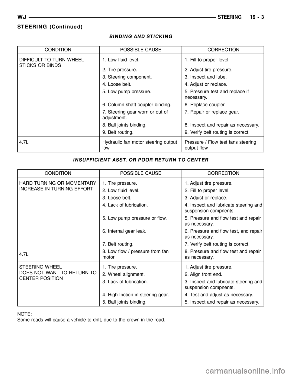
BINDING AND STICKING
CONDITION POSSIBLE CAUSE CORRECTION
DIFFICULT TO TURN WHEEL
STICKS OR BINDS1. Low fluid level. 1. Fill to proper level.
2. Tire pressure. 2. Adjust tire pressure.
3. Steering component. 3. Inspect and lube.
4. Loose belt. 4. Adjust or replace.
5. Low pump pressure. 5. Pressure test and replace if
necessary.
6. Column shaft coupler binding. 6. Replace coupler.
7. Steering gear worn or out of
adjustment.7. Repair or replace gear.
8. Ball joints binding. 8. Inspect and repair as necessary.
9. Belt routing. 9. Verify belt routing is correct.
4.7L Hydraulic fan motor steering output
lowPressure / Flow test fans steering
output flow
INSUFFICIENT ASST. OR POOR RETURN TO CENTER
CONDITION POSSIBLE CAUSE CORRECTION
HARD TURNING OR MOMENTARY
INCREASE IN TURNING EFFORT1. Tire pressure. 1. Adjust tire pressure.
2. Low fluid level. 2. Fill to proper level.
3. Loose belt. 3. Adjust or replace.
4. Lack of lubrication. 4. Inspect and lubricate steering and
suspension compnents.
5. Low pump pressure or flow. 5. Pressure and flow test and repair
as necessary.
6. Internal gear leak. 6. Pressure and flow test, and repair
as necessary.
7. Belt routing. 7. Verify belt routing is correct.
4.7L8. Low flow / pressure from fan
motor8. Pressure and flow test and repair
as necessary.
STEERING WHEEL
DOES NOT WANT TO RETURN TO
CENTER POSITION1. Tire pressure. 1. Adjust tire pressure.
2. Wheel alignment. 2. Align front end.
3. Lack of lubrication. 3. Inspect and lubricate steering and
suspension compnents.
4. High friction in steering gear. 4. Test and adjust as necessary.
5. Ball joints binding. 5. Inspect and repair as necessary.
NOTE:
Some roads will cause a vehicle to drift, due to the crown in the road.
WJSTEERING 19 - 3
STEERING (Continued)