width JEEP GRAND CHEROKEE 2002 WJ / 2.G User Guide
[x] Cancel search | Manufacturer: JEEP, Model Year: 2002, Model line: GRAND CHEROKEE, Model: JEEP GRAND CHEROKEE 2002 WJ / 2.GPages: 2199, PDF Size: 76.01 MB
Page 1258 of 2199
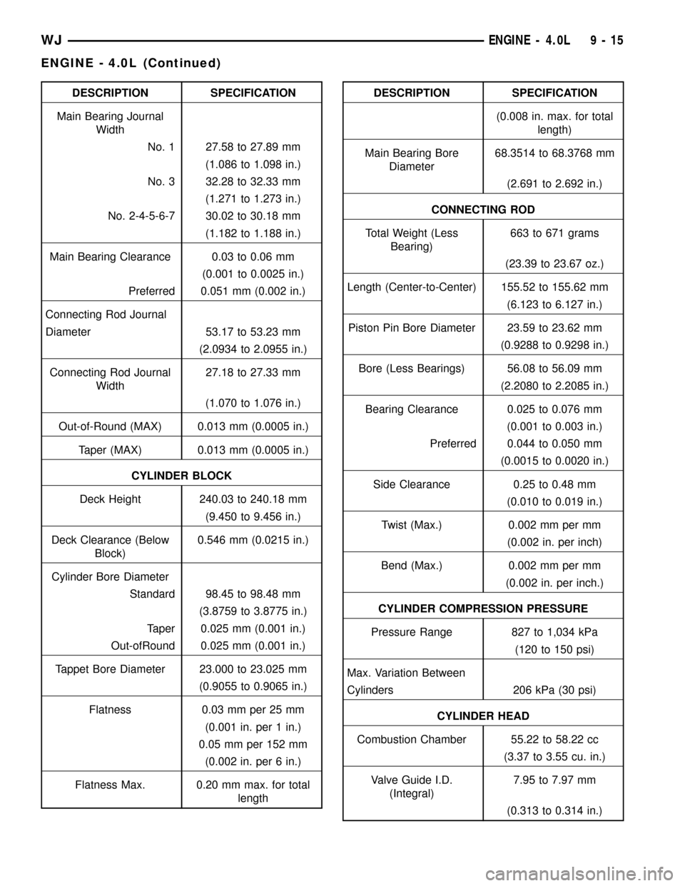
DESCRIPTION SPECIFICATION
Main Bearing Journal
Width
No. 1 27.58 to 27.89 mm
(1.086 to 1.098 in.)
No. 3 32.28 to 32.33 mm
(1.271 to 1.273 in.)
No. 2-4-5-6-7 30.02 to 30.18 mm
(1.182 to 1.188 in.)
Main Bearing Clearance 0.03 to 0.06 mm
(0.001 to 0.0025 in.)
Preferred 0.051 mm (0.002 in.)
Connecting Rod Journal
Diameter 53.17 to 53.23 mm
(2.0934 to 2.0955 in.)
Connecting Rod Journal
Width27.18 to 27.33 mm
(1.070 to 1.076 in.)
Out-of-Round (MAX) 0.013 mm (0.0005 in.)
Taper (MAX) 0.013 mm (0.0005 in.)
CYLINDER BLOCK
Deck Height 240.03 to 240.18 mm
(9.450 to 9.456 in.)
Deck Clearance (Below
Block)0.546 mm (0.0215 in.)
Cylinder Bore Diameter
Standard 98.45 to 98.48 mm
(3.8759 to 3.8775 in.)
Taper 0.025 mm (0.001 in.)
Out-ofRound 0.025 mm (0.001 in.)
Tappet Bore Diameter 23.000 to 23.025 mm
(0.9055 to 0.9065 in.)
Flatness 0.03 mm per 25 mm
(0.001 in. per 1 in.)
0.05 mm per 152 mm
(0.002 in. per 6 in.)
Flatness Max. 0.20 mm max. for total
lengthDESCRIPTION SPECIFICATION
(0.008 in. max. for total
length)
Main Bearing Bore
Diameter68.3514 to 68.3768 mm
(2.691 to 2.692 in.)
CONNECTING ROD
Total Weight (Less
Bearing)663 to 671 grams
(23.39 to 23.67 oz.)
Length (Center-to-Center) 155.52 to 155.62 mm
(6.123 to 6.127 in.)
Piston Pin Bore Diameter 23.59 to 23.62 mm
(0.9288 to 0.9298 in.)
Bore (Less Bearings) 56.08 to 56.09 mm
(2.2080 to 2.2085 in.)
Bearing Clearance 0.025 to 0.076 mm
(0.001 to 0.003 in.)
Preferred 0.044 to 0.050 mm
(0.0015 to 0.0020 in.)
Side Clearance 0.25 to 0.48 mm
(0.010 to 0.019 in.)
Twist (Max.) 0.002 mm per mm
(0.002 in. per inch)
Bend (Max.) 0.002 mm per mm
(0.002 in. per inch.)
CYLINDER COMPRESSION PRESSURE
Pressure Range 827 to 1,034 kPa
(120 to 150 psi)
Max. Variation Between
Cylinders 206 kPa (30 psi)
CYLINDER HEAD
Combustion Chamber 55.22 to 58.22 cc
(3.37 to 3.55 cu. in.)
Valve Guide I.D.
(Integral)7.95 to 7.97 mm
(0.313 to 0.314 in.)
WJENGINE - 4.0L 9 - 15
ENGINE - 4.0L (Continued)
Page 1259 of 2199
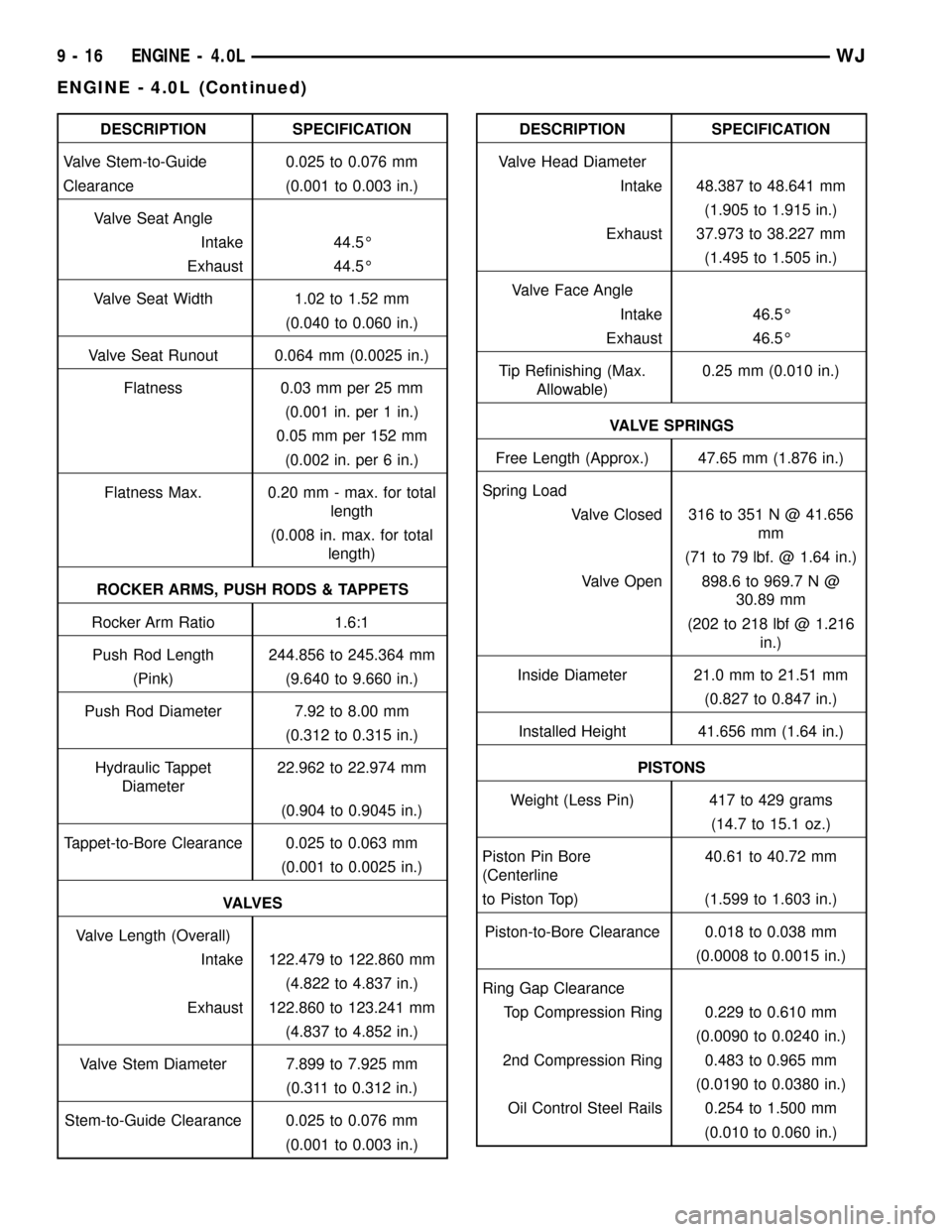
DESCRIPTION SPECIFICATION
Valve Stem-to-Guide 0.025 to 0.076 mm
Clearance (0.001 to 0.003 in.)
Valve Seat Angle
Intake 44.5É
Exhaust 44.5É
Valve Seat Width 1.02 to 1.52 mm
(0.040 to 0.060 in.)
Valve Seat Runout 0.064 mm (0.0025 in.)
Flatness 0.03 mm per 25 mm
(0.001 in. per 1 in.)
0.05 mm per 152 mm
(0.002 in. per 6 in.)
Flatness Max. 0.20 mm - max. for total
length
(0.008 in. max. for total
length)
ROCKER ARMS, PUSH RODS & TAPPETS
Rocker Arm Ratio 1.6:1
Push Rod Length 244.856 to 245.364 mm
(Pink) (9.640 to 9.660 in.)
Push Rod Diameter 7.92 to 8.00 mm
(0.312 to 0.315 in.)
Hydraulic Tappet
Diameter22.962 to 22.974 mm
(0.904 to 0.9045 in.)
Tappet-to-Bore Clearance 0.025 to 0.063 mm
(0.001 to 0.0025 in.)
VA LV E S
Valve Length (Overall)
Intake 122.479 to 122.860 mm
(4.822 to 4.837 in.)
Exhaust 122.860 to 123.241 mm
(4.837 to 4.852 in.)
Valve Stem Diameter 7.899 to 7.925 mm
(0.311 to 0.312 in.)
Stem-to-Guide Clearance 0.025 to 0.076 mm
(0.001 to 0.003 in.)DESCRIPTION SPECIFICATION
Valve Head Diameter
Intake 48.387 to 48.641 mm
(1.905 to 1.915 in.)
Exhaust 37.973 to 38.227 mm
(1.495 to 1.505 in.)
Valve Face Angle
Intake 46.5É
Exhaust 46.5É
Tip Refinishing (Max.
Allowable)0.25 mm (0.010 in.)
VALVE SPRINGS
Free Length (Approx.) 47.65 mm (1.876 in.)
Spring Load
Valve Closed 316 to 351 N @ 41.656
mm
(71 to 79 lbf. @ 1.64 in.)
Valve Open 898.6 to 969.7 N @
30.89 mm
(202 to 218 lbf @ 1.216
in.)
Inside Diameter 21.0 mm to 21.51 mm
(0.827 to 0.847 in.)
Installed Height 41.656 mm (1.64 in.)
PISTONS
Weight (Less Pin) 417 to 429 grams
(14.7 to 15.1 oz.)
Piston Pin Bore
(Centerline40.61 to 40.72 mm
to Piston Top) (1.599 to 1.603 in.)
Piston-to-Bore Clearance 0.018 to 0.038 mm
(0.0008 to 0.0015 in.)
Ring Gap Clearance
Top Compression Ring 0.229 to 0.610 mm
(0.0090 to 0.0240 in.)
2nd Compression Ring 0.483 to 0.965 mm
(0.0190 to 0.0380 in.)
Oil Control Steel Rails 0.254 to 1.500 mm
(0.010 to 0.060 in.)
9 - 16 ENGINE - 4.0LWJ
ENGINE - 4.0L (Continued)
Page 1266 of 2199
CLEANING
Remove any original sealer from the cover sealing
surface of the engine cylinder head and clean the
surface using a fabric cleaner.
Remove all residue from the sealing surface using
a clean, dry cloth.
INSPECTION
Inspect the engine cylinder head cover for cracks.
Replace the cover, if cracked.
The original dark grey gasket material should
NOT be removed. If sections of the gasket material
are missing or are compressed, replace the engine
cylinder head cover. However, sections with minor
damage such as small cracks, cuts or chips may be
repaired with a hand held applicator. The new mate-
rial must be smoothed over to maintain gasket
height. Allow the gasket material to cure prior to
engine cylinder head cover installation.
INSTALLATION
The cylinder head cover is isolated from the cylin-
der head via grommets and a reusable molded rubber
gasket. The grommet and limiter are retained in the
cylinder head cover.
(1) If a replacement cover is installed, transfer the
CCV valve grommet and oil filler cap from the origi-
nal cover to the replacement cover.
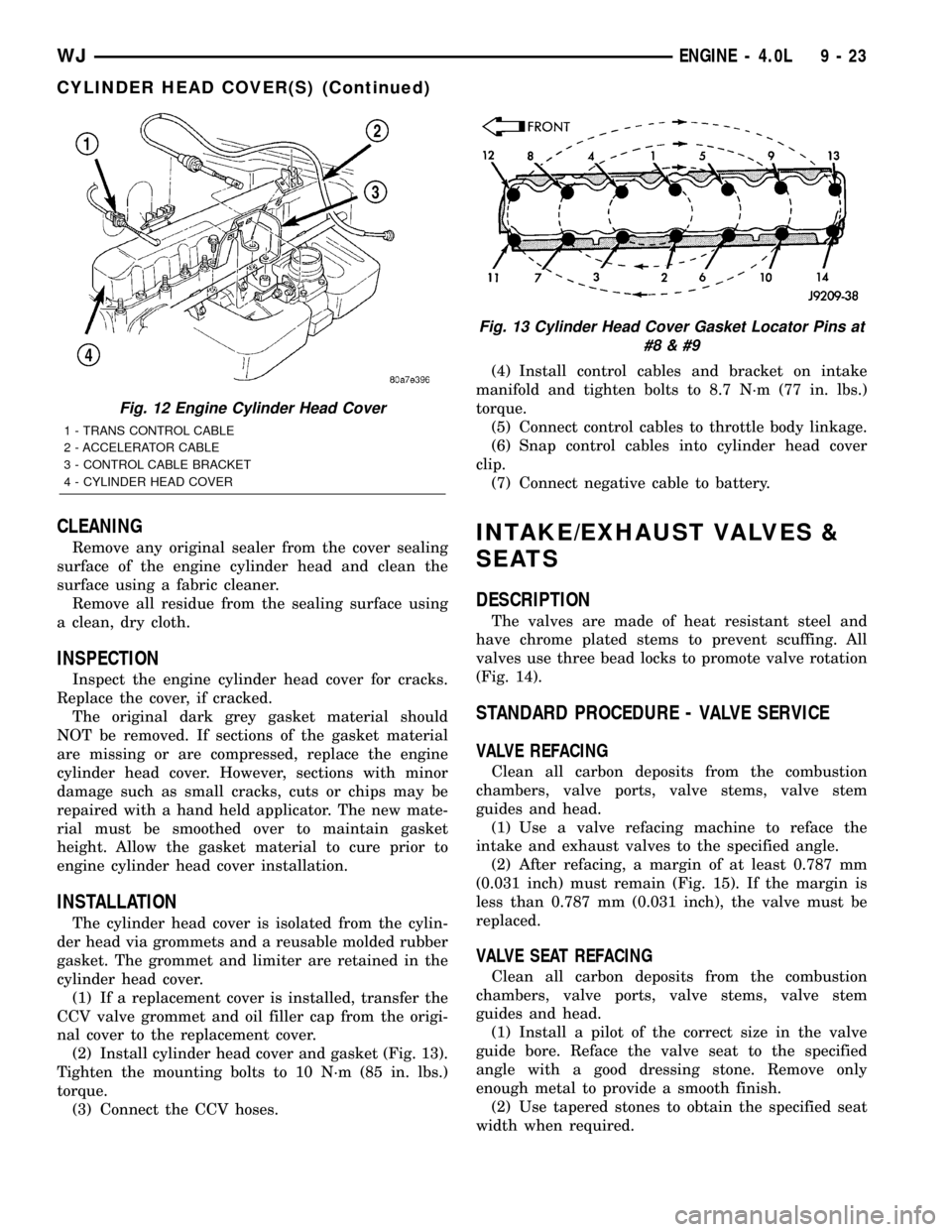
(2) Install cylinder head cover and gasket (Fig. 13).
Tighten the mounting bolts to 10 N´m (85 in. lbs.)
torque.
(3) Connect the CCV hoses.(4) Install control cables and bracket on intake
manifold and tighten bolts to 8.7 N´m (77 in. lbs.)
torque.
(5) Connect control cables to throttle body linkage.
(6) Snap control cables into cylinder head cover
clip.
(7) Connect negative cable to battery.
INTAKE/EXHAUST VALVES &
SEATS
DESCRIPTION
The valves are made of heat resistant steel and
have chrome plated stems to prevent scuffing. All
valves use three bead locks to promote valve rotation
(Fig. 14).
STANDARD PROCEDURE - VALVE SERVICE
VALVE REFACING
Clean all carbon deposits from the combustion
chambers, valve ports, valve stems, valve stem
guides and head.
(1) Use a valve refacing machine to reface the
intake and exhaust valves to the specified angle.
(2) After refacing, a margin of at least 0.787 mm
(0.031 inch) must remain (Fig. 15). If the margin is
less than 0.787 mm (0.031 inch), the valve must be
replaced.
VALVE SEAT REFACING
Clean all carbon deposits from the combustion
chambers, valve ports, valve stems, valve stem
guides and head.
(1) Install a pilot of the correct size in the valve
guide bore. Reface the valve seat to the specified
angle with a good dressing stone. Remove only
enough metal to provide a smooth finish.
(2) Use tapered stones to obtain the specified seat
width when required.
Fig. 12 Engine Cylinder Head Cover
1 - TRANS CONTROL CABLE
2 - ACCELERATOR CABLE
3 - CONTROL CABLE BRACKET
4 - CYLINDER HEAD COVER
Fig. 13 Cylinder Head Cover Gasket Locator Pins at
#8
WJENGINE - 4.0L 9 - 23
CYLINDER HEAD COVER(S) (Continued)
Page 1277 of 2199
BEARING-TO-JOURNAL CLEARANCE
(1) Wipe the oil from the connecting rod journal.
(2) Use short rubber hose sections over rod bolts
during installation.
(3) Lubricate the upper bearing insert and install
in connecting rod.
(4) Use piston ring compressor to install the rod
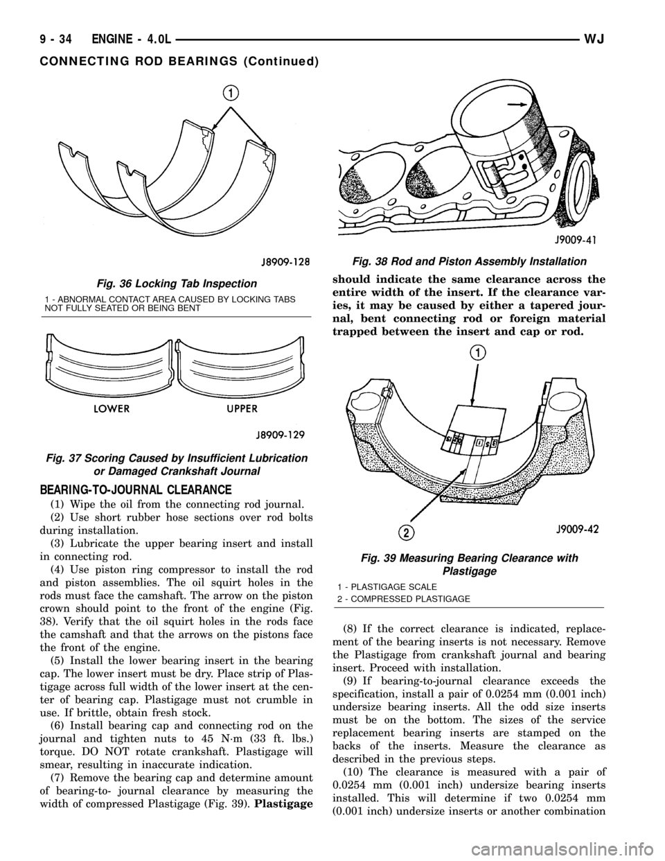
and piston assemblies. The oil squirt holes in the
rods must face the camshaft. The arrow on the piston
crown should point to the front of the engine (Fig.
38). Verify that the oil squirt holes in the rods face
the camshaft and that the arrows on the pistons face
the front of the engine.
(5) Install the lower bearing insert in the bearing
cap. The lower insert must be dry. Place strip of Plas-
tigage across full width of the lower insert at the cen-
ter of bearing cap. Plastigage must not crumble in
use. If brittle, obtain fresh stock.
(6) Install bearing cap and connecting rod on the
journal and tighten nuts to 45 N´m (33 ft. lbs.)
torque. DO NOT rotate crankshaft. Plastigage will
smear, resulting in inaccurate indication.
(7) Remove the bearing cap and determine amount
of bearing-to- journal clearance by measuring the
width of compressed Plastigage (Fig. 39).Plastigageshould indicate the same clearance across the
entire width of the insert. If the clearance var-
ies, it may be caused by either a tapered jour-
nal, bent connecting rod or foreign material
trapped between the insert and cap or rod.
(8) If the correct clearance is indicated, replace-
ment of the bearing inserts is not necessary. Remove
the Plastigage from crankshaft journal and bearing
insert. Proceed with installation.
(9) If bearing-to-journal clearance exceeds the
specification, install a pair of 0.0254 mm (0.001 inch)
undersize bearing inserts. All the odd size inserts
must be on the bottom. The sizes of the service
replacement bearing inserts are stamped on the
backs of the inserts. Measure the clearance as
described in the previous steps.
(10) The clearance is measured with a pair of
0.0254 mm (0.001 inch) undersize bearing inserts
installed. This will determine if two 0.0254 mm
(0.001 inch) undersize inserts or another combination
Fig. 36 Locking Tab Inspection
1 - ABNORMAL CONTACT AREA CAUSED BY LOCKING TABS
NOT FULLY SEATED OR BEING BENT
Fig. 37 Scoring Caused by Insufficient Lubrication
or Damaged Crankshaft Journal
Fig. 38 Rod and Piston Assembly Installation
Fig. 39 Measuring Bearing Clearance with
Plastigage
1 - PLASTIGAGE SCALE
2 - COMPRESSED PLASTIGAGE
9 - 34 ENGINE - 4.0LWJ
CONNECTING ROD BEARINGS (Continued)
Page 1279 of 2199
CRANKSHAFT MAIN
BEARINGS
STANDARD PROCEDURE - FITTING
CRANKSHAFT MAIN BEARINGS
FITTING BEARINGS (CRANKSHAFT INSTALLED)
The main bearing caps, numbered (front to rear)
from 1 through 7 have an arrow to indicate the for-
ward position. The upper main bearing inserts are
grooved to provide oil channels while the lower
inserts are smooth.
Each bearing insert pair is selectively fitted to its
respective journal to obtain the specified operating
clearance. In production, the select fit is obtained by
using various-sized color-coded bearing insert pairs
as listed in the Main Bearing Fitting Chart. The
bearing color code appears on the edge of the insert.
The size is not stamped on bearing inserts used
for engine production.
The main bearing journal size (diameter) is identi-
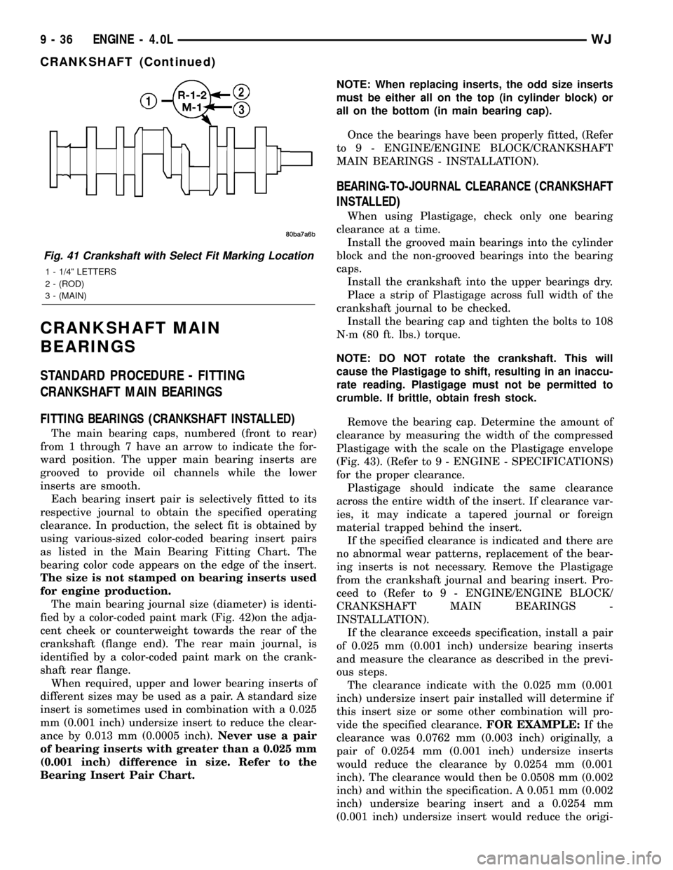
fied by a color-coded paint mark (Fig. 42)on the adja-
cent cheek or counterweight towards the rear of the
crankshaft (flange end). The rear main journal, is
identified by a color-coded paint mark on the crank-
shaft rear flange.
When required, upper and lower bearing inserts of
different sizes may be used as a pair. A standard size
insert is sometimes used in combination with a 0.025
mm (0.001 inch) undersize insert to reduce the clear-
ance by 0.013 mm (0.0005 inch).Never use a pair
of bearing inserts with greater than a 0.025 mm
(0.001 inch) difference in size. Refer to the
Bearing Insert Pair Chart.NOTE: When replacing inserts, the odd size inserts
must be either all on the top (in cylinder block) or
all on the bottom (in main bearing cap).
Once the bearings have been properly fitted, (Refer
to 9 - ENGINE/ENGINE BLOCK/CRANKSHAFT
MAIN BEARINGS - INSTALLATION).
BEARING-TO-JOURNAL CLEARANCE (CRANKSHAFT
INSTALLED)
When using Plastigage, check only one bearing
clearance at a time.
Install the grooved main bearings into the cylinder
block and the non-grooved bearings into the bearing
caps.
Install the crankshaft into the upper bearings dry.
Place a strip of Plastigage across full width of the
crankshaft journal to be checked.
Install the bearing cap and tighten the bolts to 108
N´m (80 ft. lbs.) torque.
NOTE: DO NOT rotate the crankshaft. This will
cause the Plastigage to shift, resulting in an inaccu-
rate reading. Plastigage must not be permitted to
crumble. If brittle, obtain fresh stock.
Remove the bearing cap. Determine the amount of
clearance by measuring the width of the compressed
Plastigage with the scale on the Plastigage envelope
(Fig. 43). (Refer to 9 - ENGINE - SPECIFICATIONS)
for the proper clearance.
Plastigage should indicate the same clearance
across the entire width of the insert. If clearance var-
ies, it may indicate a tapered journal or foreign
material trapped behind the insert.
If the specified clearance is indicated and there are
no abnormal wear patterns, replacement of the bear-
ing inserts is not necessary. Remove the Plastigage
from the crankshaft journal and bearing insert. Pro-
ceed to (Refer to 9 - ENGINE/ENGINE BLOCK/
CRANKSHAFT MAIN BEARINGS -
INSTALLATION).
If the clearance exceeds specification, install a pair
of 0.025 mm (0.001 inch) undersize bearing inserts
and measure the clearance as described in the previ-
ous steps.
The clearance indicate with the 0.025 mm (0.001
inch) undersize insert pair installed will determine if
this insert size or some other combination will pro-
vide the specified clearance.FOR EXAMPLE:If the
clearance was 0.0762 mm (0.003 inch) originally, a
pair of 0.0254 mm (0.001 inch) undersize inserts
would reduce the clearance by 0.0254 mm (0.001
inch). The clearance would then be 0.0508 mm (0.002
inch) and within the specification. A 0.051 mm (0.002
inch) undersize bearing insert and a 0.0254 mm
(0.001 inch) undersize insert would reduce the origi-
Fig. 41 Crankshaft with Select Fit Marking Location
1 - 1/4º LETTERS
2 - (ROD)
3 - (MAIN)
9 - 36 ENGINE - 4.0LWJ
CRANKSHAFT (Continued)
Page 1313 of 2199
STANDARD PROCEDURE
STANDARD PROCEDURE - REPAIR DAMAGED
OR WORN THREADS
CAUTION: Be sure that the tapped holes maintain
the original center line.
Damaged or worn threads can be repaired. Essen-
tially, this repair consists of:
²Drilling out worn or damaged threads.
²Tapping the hole with a special Heli-Coil Tap, or
equivalent.
²Installing an insert into the tapped hole to bring
the hole back to its original thread size.
STANDARD PROCEDURE - FORM-IN-PLACE
GASKETS AND SEALERS
There are numerous places where form-in-place
gaskets are used on the engine. Care must be taken
when applying form-in-place gaskets to assure
obtaining the desired results.Do not use form-in-
place gasket material unless specified.Bead size,
continuity, and location are of great importance. Too
thin a bead can result in leakage while too much can
result in spill-over which can break off and obstruct
fluid feed lines. A continuous bead of the proper
width is essential to obtain a leak-free gasket.
There are numerous types of form-in-place gasket
materials that are used in the engine area. Mopart
Engine RTV GEN II, MopartATF-RTV, and Mopart
Gasket Maker gasket materials, each have different
properties and can not be used in place of the other.
MOPARtENGINE RTV GEN II
MopartEngine RTV GEN II is used to seal com-
ponents exposed to engine oil. This material is a spe-
cially designed black silicone rubber RTV that
retains adhesion and sealing properties when
exposed to engine oil. Moisture in the air causes the
material to cure. This material is available in three
ounce tubes and has a shelf life of one year. After one
year this material will not properly cure. Always
inspect the package for the expiration date before
use.
MOPARtATF RTV
MopartATF RTV is a specifically designed black
silicone rubber RTV that retains adhesion and seal-
ing properties to seal components exposed to auto-
matic transmission fluid, engine coolants, and
moisture. This material is available in three ounce
tubes and has a shelf life of one year. After one year
this material will not properly cure. Always inspect
the package for the expiration date before use.
MOPARtGASKET MAKER
MopartGasket Maker is an anaerobic type gasket
material. The material cures in the absence of airwhen squeezed between two metallic surfaces. It will
not cure if left in the uncovered tube. The anaerobic
material is for use between two machined surfaces.
Do not use on flexible metal flanges.
MOPARtGASKET SEALANT
MopartGasket Sealant is a slow drying, perma-
nently soft sealer. This material is recommended for
sealing threaded fittings and gaskets against leakage
of oil and coolant. Can be used on threaded and
machined parts under all temperatures. This mate-
rial is used on engines with multi-layer steel (MLS)
cylinder head gaskets. This material also will pre-
vent corrosion. MopartGasket Sealant is available in
a 13 oz. aerosol can or 4oz./16 oz. can w/applicator.
FORM-IN-PLACE GASKET AND SEALER
APPLICATION
Assembling parts using a form-in-place gasket
requires care but it's easier then using precut gas-
kets.
MopartGasket Maker material should be applied
sparingly 1 mm (0.040 in.) diameter or less of sealant
to one gasket surface. Be certain the material sur-
rounds each mounting hole. Excess material can eas-
ily be wiped off. Components should be torqued in
place within 15 minutes. The use of a locating dowel
is recommended during assembly to prevent smear-
ing material off the location.
MopartEngine RTV GEN II or ATF RTV gasket
material should be applied in a continuous bead
approximately 3 mm (0.120 in.) in diameter. All
mounting holes must be circled. For corner sealing, a
3.17 or 6.35 mm (1/8 or 1/4 in.) drop is placed in the
center of the gasket contact area. Uncured sealant
may be removed with a shop towel. Components
should be torqued in place while the sealant is still
wet to the touch (within 10 minutes). The usage of a
locating dowel is recommended during assembly to
prevent smearing material off the location.
MopartGasket Sealant in an aerosol can should be
applied using a thin, even coat sprayed completely
over both surfaces to be joined, and both sides of a
gasket. Then proceed with assembly. Material in a
can w/applicator can be brushed on evenly over the
sealing surfaces. Material in an aerosol can should be
used on engines with multi-layer steel gaskets.
STANDARD PROCEDURE - ENGINE GASKET
SURFACE PREPARATION
To ensure engine gasket sealing, proper surface
preparation must be performed, especially with the
use of aluminum engine components and multi-layer
steel cylinder head gaskets.
Neveruse the following to clean gasket surfaces:
²Metal scraper
9 - 70 ENGINE - 4.7LWJ
ENGINE - 4.7L (Continued)
Page 1318 of 2199
DESCRIPTION SPECIFICATION
PISTON RINGS
Ring Gap
Top Compression Ring 0.37 - 0.63 mm
(0.0146 - 0.0249 in.)
Second Compression
Ring0.37 - 0.63 mm
(0.0146 - 0.0249 in.)
Oil Control (Steel Rails) 0.25 - 0.76 mm
(0.0099 - 0.30 in.)
Side Clearance
Top Compression Ring .051 - .094 mm
(0.0020 - 0.0037 in.)
Second Compression
Ring0.040 - 0.080 mm
(0.0016 - 0.0031 in.)
Oil Ring (Steel Ring) .019 - .229 mm
(.0007 - .0091 in.)
Ring Width
Top Compression Ring 1.472 - 1.490 mm
(0.057 - 0.058 in.)
Second Compression
Ring1.472 - 1.490 mm
(0.057 - 0.058 in.)
Oil Ring (Steel Rails) 0.445 - 0.470 mm
(0.017 - 0.018 in.)
CONNECTING RODS
Bearing Clearance 0.010 - 0.048 mm
(0.0004 - 0.0019 in.)
Side Clearance 0.10 - 0.35 mm
(0.004 - 0.0138 in.)
Piston Pin Bore Diameter .022 - .045 mm
(Interference Fit) (0.0009 - 0.0018 in.)
Bearing Bore Out of
Round0.004 mm
(MAX) (0.0002 in.)
Total Weight (Less
Bearing)555 grams (19.5771
ounces)
CRANKSHAFT
Main BearingJournal
Diameter 63.488 - 63.512 mm
(2.4996 - 2.5005 in.)DESCRIPTION SPECIFICATION
Bearing Clearance 0.018 - 0.052 mm
(0.0008 - 0.0021 in.)
Out of Round (MAX) 0.005 mm (0.0002 in.)
Taper (MAX) 0.008 mm (0.0004 in.)
End Play 0.052 - 0.282 mm
(0.0021 - 0.0112 in.)
End Play (MAX) 0.282 mm (0.0112 in)
Connecting Rod
Journal
Diameter 50.992 - 51.008 mm
(2.0076 - 2.0082 in.)
Bearing Clearance 0.015 - 0.055 mm
(0.0006 -0.0022 in.)
Out of Round (MAX) 0.005 mm (0.0002 in.)
Taper (MAX) 0.008 mm (0.0004 in.)
CAMSHAFT
Bore Diameter 26.02 - 26.04 mm
(1.0245 - 1.0252 in.)
Bearing Journal Diameter 25.975 - 25.995 mm
(1.0227 - 1.0235 in.)
Bearing Clearance 0.025 - 0.065 mm
(0.001 - 0.0026 in.)
Bearing Clearance (MAX) 0.065 mm (0.0026 in.)
End Play .075 - .200 mm
(0.003 - 0.0079 in.)
End Play (MAX) .200 mm (0.0079 in.)
VALVE TIMING
Intake
Opens (ATDC) 3.6É
Closes (ATDC) 247.1É
Duration 243.5É
Exhaust
Opens (BTDC) 232.5É
Closes (ATDC) 21.2É
Duration 253.70É
Valve Overlap 17.6É
VA LV E S
Face Angle 45É - 45.5É
Head Diameter
Intake 48.52 - 48.78 mm
(1.9103 - 1.9205 in.)
WJENGINE - 4.7L 9 - 75
ENGINE - 4.7L (Continued)
Page 1319 of 2199
DESCRIPTION SPECIFICATION
Exhaust 36.87 - 37.13 mm
1.4516 - 1.4618 in.)
Length (Overall)
Intake 113.45 - 114.21 mm
(4.4666 - 4.4965)
Exhaust 114.92 - 115.68 mm
(4.5244 - 4.5543 in.)
Stem Diameter
Intake 6.931 - 6.957 mm
(0.2729 - 0.2739 in.)
Exhaust 6.902 - 6.928 mm
(0.2717 - 0.2728 in.)
Stem - to - Guide
Clearance
Intake .018 - .069 mm
(0.0008 - 0.0028 in.)
Exhaust .047 - .098 mm
(0.0019 - 0.0039 in.)
Max. Allowable Stem -
to -
Guide Clearance
(Rocking
Method)
Intake 0.069 mm (0.0028 in.)
Exhaust 0.098 mm (0.0039 in.)
Valve Lift (Zero Lash)
Intake 11.25 mm (0.443 in.)
Exhaust 10.90 mm (0.4292 in.)
VALVE SPRING
Free Length (Approx)
Intake and Exhaust 48.6 mm (1.9134 in.)
Spring Force (Valve
Closed)
Intake and Exhaust 315.5 - 352.5 N @ 40.89
mm
(70.92722 - 79.24515 lbs.
@ 1.6099 in.)DESCRIPTION SPECIFICATION
Spring Force (Valve
Open)
Intake and Exhaust 786.0 - 860.0 N @ 29.64
mm
176.6998 - 193.3357 lbs.
@ 1.167 in.)
Number of Coils
Intake and Exhaust 6.69
Wire Diameter
Intake and Exhaust 4.2799 - 4.3561 mm
(0.1685 - 0.1715 in.)
Installed Height (Spring
Seat to Bottom of
Retainer)
Nominal
Intake 40.97 mm (1.613 in.)
Exhaust 40.81 mm (1.606 in.)
CYLINDER HEAD
Gasket Thickness
(Compressed) .7 mm (0.0276 in.)
Valve Seat Angle 44.5É - 45.0É
Valve Seat Runout (MAX) 0.051 mm (0.002 in.)
Valve Seat Width
Intake 1.75 - 2.36 mm
(0.0698 - 0.0928 in.)
Exhaust 1.71 - 2.32 mm
(0.0673 - 0.0911 in.)
Guide Bore Diameter
(Std.)6.975 - 7.00 mm
(0.2747 - 0.2756 in.)
Cylinder Head Warpage
(Flatness) 0.0508 mm (0.002 in.)
OIL PUMP
Clearance Over Rotors /
End Face (MAX).035 - .095 mm
(0.0014 - 0.0038 in.)
Cover Out - of -Flat
(MAX).025 mm (0.001 in.)
Inner and Outer Rotor
Thickness 12.02 mm (0.4731 in.)
9 - 76 ENGINE - 4.7LWJ
ENGINE - 4.7L (Continued)
Page 1320 of 2199
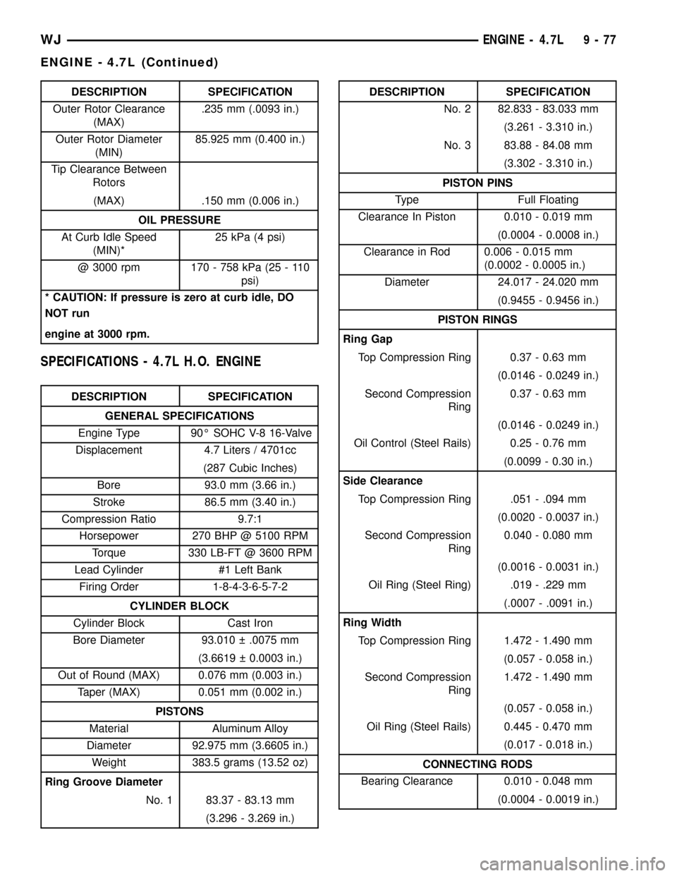
DESCRIPTION SPECIFICATION
Outer Rotor Clearance
(MAX).235 mm (.0093 in.)
Outer Rotor Diameter
(MIN)85.925 mm (0.400 in.)
Tip Clearance Between
Rotors
(MAX) .150 mm (0.006 in.)
OIL PRESSURE
At Curb Idle Speed
(MIN)*25 kPa (4 psi)
@ 3000 rpm 170 - 758 kPa (25 - 110
psi)
* CAUTION: If pressure is zero at curb idle, DO
NOT run
engine at 3000 rpm.
SPECIFICATIONS - 4.7L H.O. ENGINE
DESCRIPTION SPECIFICATION
GENERAL SPECIFICATIONS
Engine Type 90É SOHC V-8 16-Valve
Displacement 4.7 Liters / 4701cc
(287 Cubic Inches)
Bore 93.0 mm (3.66 in.)
Stroke 86.5 mm (3.40 in.)
Compression Ratio 9.7:1
Horsepower 270 BHP @ 5100 RPM
Torque 330 LB-FT @ 3600 RPM
Lead Cylinder #1 Left Bank
Firing Order 1-8-4-3-6-5-7-2
CYLINDER BLOCK
Cylinder Block Cast Iron
Bore Diameter 93.010 .0075 mm
(3.6619 0.0003 in.)
Out of Round (MAX) 0.076 mm (0.003 in.)
Taper (MAX) 0.051 mm (0.002 in.)
PISTONS
Material Aluminum Alloy
Diameter 92.975 mm (3.6605 in.)
Weight 383.5 grams (13.52 oz)
Ring Groove Diameter
No. 1 83.37 - 83.13 mm
(3.296 - 3.269 in.)
DESCRIPTION SPECIFICATION
No. 2 82.833 - 83.033 mm
(3.261 - 3.310 in.)
No. 3 83.88 - 84.08 mm
(3.302 - 3.310 in.)
PISTON PINS
Type Full Floating
Clearance In Piston 0.010 - 0.019 mm
(0.0004 - 0.0008 in.)
Clearance in Rod 0.006 - 0.015 mm
(0.0002 - 0.0005 in.)
Diameter 24.017 - 24.020 mm
(0.9455 - 0.9456 in.)
PISTON RINGS
Ring Gap
Top Compression Ring 0.37 - 0.63 mm
(0.0146 - 0.0249 in.)
Second Compression
Ring0.37 - 0.63 mm
(0.0146 - 0.0249 in.)
Oil Control (Steel Rails) 0.25 - 0.76 mm
(0.0099 - 0.30 in.)
Side Clearance
Top Compression Ring .051 - .094 mm
(0.0020 - 0.0037 in.)
Second Compression
Ring0.040 - 0.080 mm
(0.0016 - 0.0031 in.)
Oil Ring (Steel Ring) .019 - .229 mm
(.0007 - .0091 in.)
Ring Width
Top Compression Ring 1.472 - 1.490 mm
(0.057 - 0.058 in.)
Second Compression
Ring1.472 - 1.490 mm
(0.057 - 0.058 in.)
Oil Ring (Steel Rails) 0.445 - 0.470 mm
(0.017 - 0.018 in.)
CONNECTING RODS
Bearing Clearance 0.010 - 0.048 mm
(0.0004 - 0.0019 in.)
WJENGINE - 4.7L 9 - 77
ENGINE - 4.7L (Continued)
Page 1322 of 2199
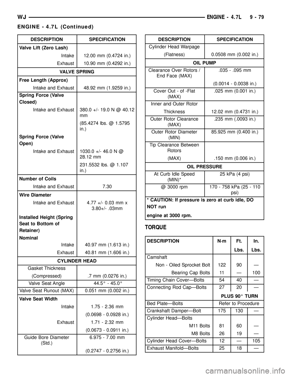
DESCRIPTION SPECIFICATION
Valve Lift (Zero Lash)
Intake 12.00 mm (0.4724 in.)
Exhaust 10.90 mm (0.4292 in.)
VALVE SPRING
Free Length (Approx)
Intake and Exhaust 48.92 mm (1.9259 in.)
Spring Force (Valve
Closed)
Intake and Exhaust 380.0 +/- 19.0 N @ 40.12
mm
(85.4274 lbs. @ 1.5795
in.)
Spring Force (Valve
Open)
Intake and Exhaust 1030.0 +/- 46.0 N @
28.12 mm
231.5532 lbs. @ 1.107
in.)
Number of Coils
Intake and Exhaust 7.30
Wire Diameter
Intake and Exhaust 4.77 +/- 0.03 mm x
3.80+/- .03mm
Installed Height (Spring
Seat to Bottom of
Retainer)
Nominal
Intake 40.97 mm (1.613 in.)
Exhaust 40.81 mm (1.606 in.)
CYLINDER HEAD
Gasket Thickness
(Compressed) .7 mm (0.0276 in.)
Valve Seat Angle 44.5É - 45.0É
Valve Seat Runout (MAX) 0.051 mm (0.002 in.)
Valve Seat Width
Intake 1.75 - 2.36 mm
(0.0698 - 0.0928 in.)
Exhaust 1.71 - 2.32 mm
(0.0673 - 0.0911 in.)
Guide Bore Diameter
(Std.)6.975 - 7.00 mm
(0.2747 - 0.2756 in.)DESCRIPTION SPECIFICATION
Cylinder Head Warpage
(Flatness) 0.0508 mm (0.002 in.)
OIL PUMP
Clearance Over Rotors /
End Face (MAX).035 - .095 mm
(0.0014 - 0.0038 in.)
Cover Out - of -Flat
(MAX).025 mm (0.001 in.)
Inner and Outer Rotor
Thickness 12.02 mm (0.4731 in.)
Outer Rotor Clearance
(MAX).235 mm (.0093 in.)
Outer Rotor Diameter
(MIN)85.925 mm (0.400 in.)
Tip Clearance Between
Rotors
(MAX) .150 mm (0.006 in.)
OIL PRESSURE
At Curb Idle Speed
(MIN)*25 kPa (4 psi)
@ 3000 rpm 170 - 758 kPa (25 - 110
psi)
* CAUTION: If pressure is zero at curb idle, DO
NOT run
engine at 3000 rpm.
TORQUE
DESCRIPTION N´m Ft. In.
Lbs. Lbs.
Camshaft
Non - Oiled Sprocket Bolt 122 90 Ð
Bearing Cap Bolts 11 Ð 100
Timing Chain CoverÐBolts 54 40 Ð
Connecting Rod CapÐBolts 27 20 Ð
PLUS 90É TURN
Bed PlateÐBolts Refer to Procedure
Crankshaft DamperÐBolt 175 130 Ð
Cylinder HeadÐBolts
M11 Bolts 81 60 Ð
M8 Bolts 26 19 Ð
Cylinder Head CoverÐBolts 12 Ð 105
Exhaust ManifoldÐBolts 25 18 Ð
WJENGINE - 4.7L 9 - 79
ENGINE - 4.7L (Continued)