width JEEP GRAND CHEROKEE 2002 WJ / 2.G Service Manual
[x] Cancel search | Manufacturer: JEEP, Model Year: 2002, Model line: GRAND CHEROKEE, Model: JEEP GRAND CHEROKEE 2002 WJ / 2.GPages: 2199, PDF Size: 76.01 MB
Page 2184 of 2199

INSTALLATION - FIXED ORIFICE FITTING
When installing fixed orifice fitting, be sure loca-
tions of fixed orifice fitting and air inlet fitting (Fig.
9) have not been inadvertently exchanged. The fixed
orifice fitting is light grey in color and is located at
rearof valve cover. The air inlet fitting is black in
color and is located atfrontof valve cover.
(1) Connect fitting to CCV breather tube.
(2) Return fixed orifice fitting to valve cover grom-
met.
EVAP/PURGE SOLENOID
DESCRIPTION
The duty cycle EVAP canister purge solenoid (DCP)
regulates the rate of vapor flow from the EVAP can-
ister to the intake manifold. The Powertrain Control
Module (PCM) operates the solenoid.
OPERATION
During the cold start warm-up period and the hot
start time delay, the PCM does not energize the sole-
noid. When de-energized, no vapors are purged. The
PCM de-energizes the solenoid during open loop oper-
ation.
The engine enters closed loop operation after it
reaches a specified temperature and the time delay
ends. During closed loop operation, the PCM cycles
(energizes and de-energizes) the solenoid 5 or 10
times per second, depending upon operating condi-
tions. The PCM varies the vapor flow rate by chang-
ing solenoid pulse width. Pulse width is the amount
of time that the solenoid is energized. The PCM
adjusts solenoid pulse width based on engine operat-
ing condition.
REMOVAL
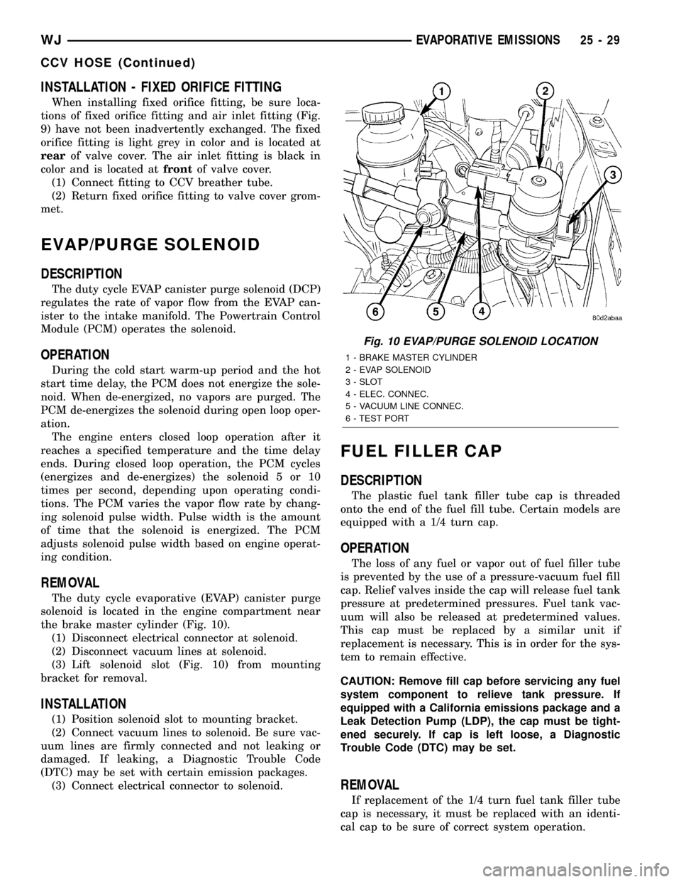
The duty cycle evaporative (EVAP) canister purge
solenoid is located in the engine compartment near
the brake master cylinder (Fig. 10).
(1) Disconnect electrical connector at solenoid.
(2) Disconnect vacuum lines at solenoid.
(3) Lift solenoid slot (Fig. 10) from mounting
bracket for removal.
INSTALLATION
(1) Position solenoid slot to mounting bracket.
(2) Connect vacuum lines to solenoid. Be sure vac-
uum lines are firmly connected and not leaking or
damaged. If leaking, a Diagnostic Trouble Code
(DTC) may be set with certain emission packages.
(3) Connect electrical connector to solenoid.
FUEL FILLER CAP
DESCRIPTION
The plastic fuel tank filler tube cap is threaded
onto the end of the fuel fill tube. Certain models are
equipped with a 1/4 turn cap.
OPERATION
The loss of any fuel or vapor out of fuel filler tube
is prevented by the use of a pressure-vacuum fuel fill
cap. Relief valves inside the cap will release fuel tank
pressure at predetermined pressures. Fuel tank vac-
uum will also be released at predetermined values.
This cap must be replaced by a similar unit if
replacement is necessary. This is in order for the sys-
tem to remain effective.
CAUTION: Remove fill cap before servicing any fuel
system component to relieve tank pressure. If
equipped with a California emissions package and a
Leak Detection Pump (LDP), the cap must be tight-
ened securely. If cap is left loose, a Diagnostic
Trouble Code (DTC) may be set.
REMOVAL
If replacement of the 1/4 turn fuel tank filler tube
cap is necessary, it must be replaced with an identi-
cal cap to be sure of correct system operation.
Fig. 10 EVAP/PURGE SOLENOID LOCATION
1 - BRAKE MASTER CYLINDER
2 - EVAP SOLENOID
3 - SLOT
4 - ELEC. CONNEC.
5 - VACUUM LINE CONNEC.
6 - TEST PORT
WJEVAPORATIVE EMISSIONS 25 - 29
CCV HOSE (Continued)