Connecting rod JEEP GRAND CHEROKEE 2002 WJ / 2.G Owner's Manual
[x] Cancel search | Manufacturer: JEEP, Model Year: 2002, Model line: GRAND CHEROKEE, Model: JEEP GRAND CHEROKEE 2002 WJ / 2.GPages: 2199, PDF Size: 76.01 MB
Page 1294 of 2199
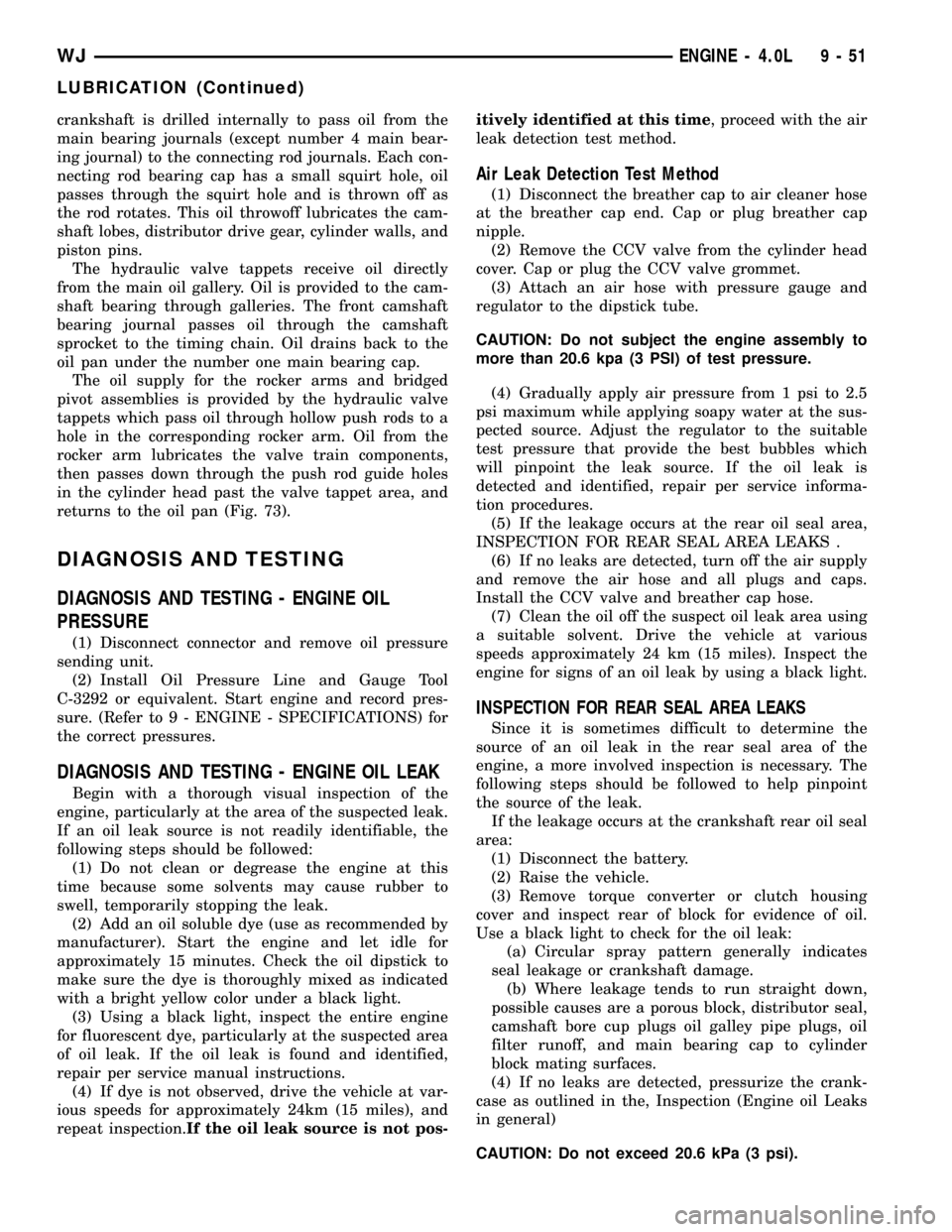
crankshaft is drilled internally to pass oil from the
main bearing journals (except number 4 main bear-
ing journal) to the connecting rod journals. Each con-
necting rod bearing cap has a small squirt hole, oil
passes through the squirt hole and is thrown off as
the rod rotates. This oil throwoff lubricates the cam-
shaft lobes, distributor drive gear, cylinder walls, and
piston pins.
The hydraulic valve tappets receive oil directly
from the main oil gallery. Oil is provided to the cam-
shaft bearing through galleries. The front camshaft
bearing journal passes oil through the camshaft
sprocket to the timing chain. Oil drains back to the
oil pan under the number one main bearing cap.
The oil supply for the rocker arms and bridged
pivot assemblies is provided by the hydraulic valve
tappets which pass oil through hollow push rods to a
hole in the corresponding rocker arm. Oil from the
rocker arm lubricates the valve train components,
then passes down through the push rod guide holes
in the cylinder head past the valve tappet area, and
returns to the oil pan (Fig. 73).
DIAGNOSIS AND TESTING
DIAGNOSIS AND TESTING - ENGINE OIL
PRESSURE
(1) Disconnect connector and remove oil pressure
sending unit.
(2) Install Oil Pressure Line and Gauge Tool
C-3292 or equivalent. Start engine and record pres-
sure. (Refer to 9 - ENGINE - SPECIFICATIONS) for
the correct pressures.
DIAGNOSIS AND TESTING - ENGINE OIL LEAK
Begin with a thorough visual inspection of the
engine, particularly at the area of the suspected leak.
If an oil leak source is not readily identifiable, the
following steps should be followed:
(1) Do not clean or degrease the engine at this
time because some solvents may cause rubber to
swell, temporarily stopping the leak.
(2) Add an oil soluble dye (use as recommended by
manufacturer). Start the engine and let idle for
approximately 15 minutes. Check the oil dipstick to
make sure the dye is thoroughly mixed as indicated
with a bright yellow color under a black light.
(3) Using a black light, inspect the entire engine
for fluorescent dye, particularly at the suspected area
of oil leak. If the oil leak is found and identified,
repair per service manual instructions.
(4) If dye is not observed, drive the vehicle at var-
ious speeds for approximately 24km (15 miles), and
repeat inspection.If the oil leak source is not pos-itively identified at this time, proceed with the air
leak detection test method.
Air Leak Detection Test Method
(1) Disconnect the breather cap to air cleaner hose
at the breather cap end. Cap or plug breather cap
nipple.
(2) Remove the CCV valve from the cylinder head
cover. Cap or plug the CCV valve grommet.
(3) Attach an air hose with pressure gauge and
regulator to the dipstick tube.
CAUTION: Do not subject the engine assembly to
more than 20.6 kpa (3 PSI) of test pressure.
(4) Gradually apply air pressure from 1 psi to 2.5
psi maximum while applying soapy water at the sus-
pected source. Adjust the regulator to the suitable
test pressure that provide the best bubbles which
will pinpoint the leak source. If the oil leak is
detected and identified, repair per service informa-
tion procedures.
(5) If the leakage occurs at the rear oil seal area,
INSPECTION FOR REAR SEAL AREA LEAKS .
(6) If no leaks are detected, turn off the air supply
and remove the air hose and all plugs and caps.
Install the CCV valve and breather cap hose.
(7) Clean the oil off the suspect oil leak area using
a suitable solvent. Drive the vehicle at various
speeds approximately 24 km (15 miles). Inspect the
engine for signs of an oil leak by using a black light.
INSPECTION FOR REAR SEAL AREA LEAKS
Since it is sometimes difficult to determine the
source of an oil leak in the rear seal area of the
engine, a more involved inspection is necessary. The
following steps should be followed to help pinpoint
the source of the leak.
If the leakage occurs at the crankshaft rear oil seal
area:
(1) Disconnect the battery.
(2) Raise the vehicle.
(3) Remove torque converter or clutch housing
cover and inspect rear of block for evidence of oil.
Use a black light to check for the oil leak:
(a) Circular spray pattern generally indicates
seal leakage or crankshaft damage.
(b) Where leakage tends to run straight down,
possible causes are a porous block, distributor seal,
camshaft bore cup plugs oil galley pipe plugs, oil
filter runoff, and main bearing cap to cylinder
block mating surfaces.
(4) If no leaks are detected, pressurize the crank-
case as outlined in the, Inspection (Engine oil Leaks
in general)
CAUTION: Do not exceed 20.6 kPa (3 psi).
WJENGINE - 4.0L 9 - 51
LUBRICATION (Continued)
Page 1305 of 2199
ROCKER ARM / ADJUSTER ASSEMBLY
DESCRIPTION........................107
REMOVAL............................107
INSTALLATION........................107
VALVE SPRINGS
DESCRIPTION........................108
VALVE STEM SEALS
DESCRIPTION........................108
ENGINE BLOCK
DESCRIPTION........................108
STANDARD PROCEDUREÐCYLINDER BORE
HONING...........................108
CLEANING...........................109
INSPECTION.........................109
CONNECTING ROD BEARINGS
STANDARD PROCEDURE - CONNECTING
ROD BEARING FITTING...............109
CRANKSHAFT
DESCRIPTION........................111
STANDARD PROCEDURE - MEASURING
CRANKSHAFT END PLAY..............111
REMOVAL............................112
INSPECTION..........................112
INSTALLATION........................112
CRANKSHAFT MAIN BEARINGS
STANDARD PROCEDUREÐCRANKSHAFT
MAIN BEARING - FITTING..............114
INSPECTION..........................115
CRANKSHAFT OIL SEAL - FRONT
REMOVAL............................115
INSTALLATION........................116
CRANKSHAFT OIL SEAL - REAR
REMOVAL............................117
INSTALLATION........................117
FLEX PLATE
REMOVAL............................118
INSTALLATION........................118
PISTON & CONNECTING ROD
DESCRIPTION........................118
STANDARD PROCEDUREÐPISTON FITTING . 118
REMOVAL............................118
CLEANING...........................119
INSPECTION..........................119
INSTALLATION........................120
PISTON RINGS
STANDARD PROCEDURE - PISTON RING
FITTING............................121
VIBRATION DAMPER
REMOVAL............................122
INSTALLATION........................123
STRUCTURAL COVER
DESCRIPTION........................124
OPERATION..........................124
REMOVAL............................124
INSTALLATION........................124
FRONT MOUNT
REMOVAL............................124INSTALLATION........................125
REAR MOUNT
REMOVAL............................125
INSTALLATION........................126
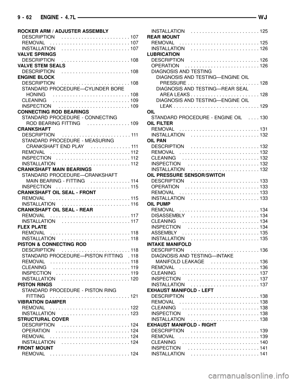
LUBRICATION
DESCRIPTION........................126
OPERATION..........................126
DIAGNOSIS AND TESTING
DIAGNOSIS AND TESTINGÐENGINE OIL
PRESSURE.........................128
DIAGNOSIS AND TESTINGÐREAR SEAL
AREA LEAKS........................128
DIAGNOSIS AND TESTINGÐENGINE OIL
LEAK..............................129
OIL
STANDARD PROCEDURE - ENGINE OIL....130
OIL FILTER
REMOVAL............................131
INSTALLATION........................132
OIL PAN
DESCRIPTION........................132
REMOVAL............................132
CLEANING...........................132
INSPECTION.........................132
INSTALLATION........................132
OIL PRESSURE SENSOR/SWITCH
DESCRIPTION........................133
OPERATION..........................133
REMOVAL............................133
INSTALLATION........................133
OIL PUMP
REMOVAL............................134
DISASSEMBLY........................134
CLEANING...........................134
INSPECTION.........................134
ASSEMBLY...........................135
INSTALLATION........................135
INTAKE MANIFOLD
DESCRIPTION........................136
DIAGNOSIS AND TESTINGÐINTAKE
MANIFOLD LEAKAGE.................136
REMOVAL............................136
CLEANING...........................137
INSPECTION.........................137
INSTALLATION........................137
EXHAUST MANIFOLD - LEFT
DESCRIPTION........................138
REMOVAL............................138
CLEANING...........................138
INSPECTION.........................138
INSTALLATION........................138
EXHAUST MANIFOLD - RIGHT
DESCRIPTION........................139
REMOVAL............................139
CLEANING...........................140
INSPECTION.........................141
INSTALLATION........................141
9 - 62 ENGINE - 4.7LWJ
Page 1309 of 2199
CONDITION POSSIBLE CAUSE CORRECTION
1. ENGINE MISSES ON
ACCELERATION1. Spark plugs dirty or incorrectly
gapped.1. (Refer to 8 - ELECTRICAL/
IGNITION CONTROL/SPARK PLUG -
CLEANING).
2. Dirt in fuel system. 2. Clean fuel system.
3. Burned, warped or pitted valves. 3. Replcae as necessary.
4. Faulty coil. 4. (Refer to 8 - ELECTRICAL/
IGNITION CONTROL/IGNITION COIL -
REMOVAL).
1. ENGINE MISSES AT HIGH
SPEED1. Spark plugs dirty or incorrectly
gapped.1. (Refer to 8 - ELECTRICAL/
IGNITION CONTROL/SPARK PLUG -
CLEANING).
2. Faulty coil. 2. (Refer to 8 - ELECTRICAL/
IGNITION CONTROL/IGNITION COIL -
REMOVAL).
3. Dirt or water in fuel system. 3. Clean system and replace fuel filter.
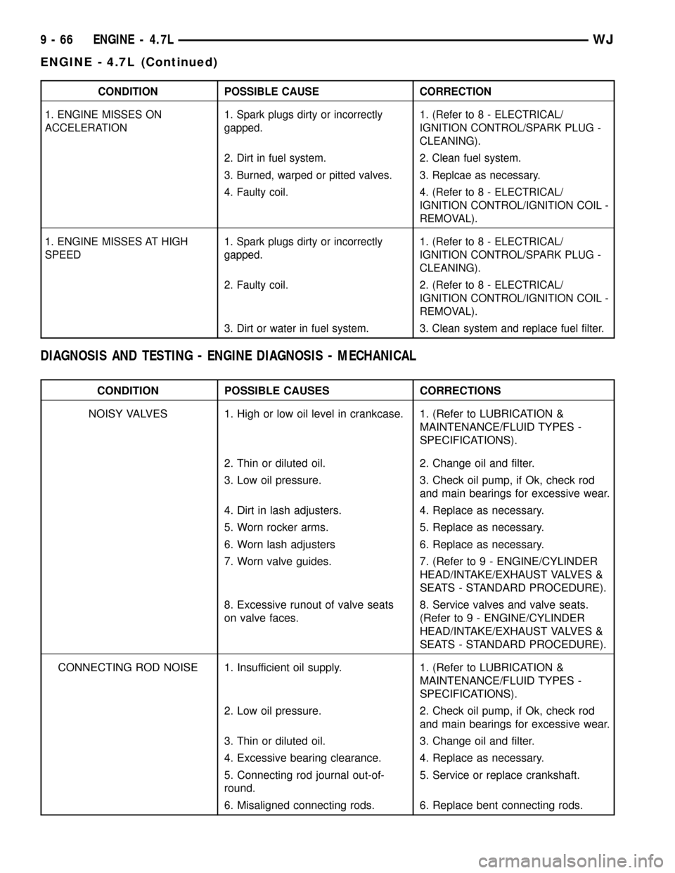
DIAGNOSIS AND TESTING - ENGINE DIAGNOSIS - MECHANICAL
CONDITION POSSIBLE CAUSES CORRECTIONS
NOISY VALVES 1. High or low oil level in crankcase. 1. (Refer to LUBRICATION &
MAINTENANCE/FLUID TYPES -
SPECIFICATIONS).
2. Thin or diluted oil. 2. Change oil and filter.
3. Low oil pressure. 3. Check oil pump, if Ok, check rod
and main bearings for excessive wear.
4. Dirt in lash adjusters. 4. Replace as necessary.
5. Worn rocker arms. 5. Replace as necessary.
6. Worn lash adjusters 6. Replace as necessary.
7. Worn valve guides. 7. (Refer to 9 - ENGINE/CYLINDER
HEAD/INTAKE/EXHAUST VALVES &
SEATS - STANDARD PROCEDURE).
8. Excessive runout of valve seats
on valve faces.8. Service valves and valve seats.
(Refer to 9 - ENGINE/CYLINDER
HEAD/INTAKE/EXHAUST VALVES &
SEATS - STANDARD PROCEDURE).
CONNECTING ROD NOISE 1. Insufficient oil supply. 1. (Refer to LUBRICATION &
MAINTENANCE/FLUID TYPES -
SPECIFICATIONS).
2. Low oil pressure. 2. Check oil pump, if Ok, check rod
and main bearings for excessive wear.
3. Thin or diluted oil. 3. Change oil and filter.
4. Excessive bearing clearance. 4. Replace as necessary.
5. Connecting rod journal out-of-
round.5. Service or replace crankshaft.
6. Misaligned connecting rods. 6. Replace bent connecting rods.
9 - 66 ENGINE - 4.7LWJ
ENGINE - 4.7L (Continued)
Page 1318 of 2199
DESCRIPTION SPECIFICATION
PISTON RINGS
Ring Gap
Top Compression Ring 0.37 - 0.63 mm
(0.0146 - 0.0249 in.)
Second Compression
Ring0.37 - 0.63 mm
(0.0146 - 0.0249 in.)
Oil Control (Steel Rails) 0.25 - 0.76 mm
(0.0099 - 0.30 in.)
Side Clearance
Top Compression Ring .051 - .094 mm
(0.0020 - 0.0037 in.)
Second Compression
Ring0.040 - 0.080 mm
(0.0016 - 0.0031 in.)
Oil Ring (Steel Ring) .019 - .229 mm
(.0007 - .0091 in.)
Ring Width
Top Compression Ring 1.472 - 1.490 mm
(0.057 - 0.058 in.)
Second Compression
Ring1.472 - 1.490 mm
(0.057 - 0.058 in.)
Oil Ring (Steel Rails) 0.445 - 0.470 mm
(0.017 - 0.018 in.)
CONNECTING RODS
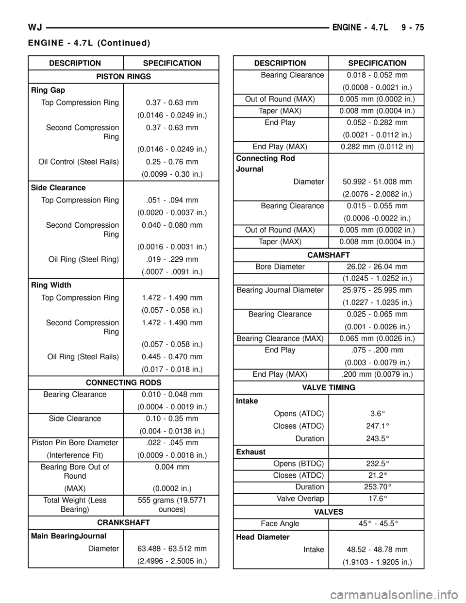
Bearing Clearance 0.010 - 0.048 mm
(0.0004 - 0.0019 in.)
Side Clearance 0.10 - 0.35 mm
(0.004 - 0.0138 in.)
Piston Pin Bore Diameter .022 - .045 mm
(Interference Fit) (0.0009 - 0.0018 in.)
Bearing Bore Out of
Round0.004 mm
(MAX) (0.0002 in.)
Total Weight (Less
Bearing)555 grams (19.5771
ounces)
CRANKSHAFT
Main BearingJournal
Diameter 63.488 - 63.512 mm
(2.4996 - 2.5005 in.)DESCRIPTION SPECIFICATION
Bearing Clearance 0.018 - 0.052 mm
(0.0008 - 0.0021 in.)
Out of Round (MAX) 0.005 mm (0.0002 in.)
Taper (MAX) 0.008 mm (0.0004 in.)
End Play 0.052 - 0.282 mm
(0.0021 - 0.0112 in.)
End Play (MAX) 0.282 mm (0.0112 in)
Connecting Rod
Journal
Diameter 50.992 - 51.008 mm
(2.0076 - 2.0082 in.)
Bearing Clearance 0.015 - 0.055 mm
(0.0006 -0.0022 in.)
Out of Round (MAX) 0.005 mm (0.0002 in.)
Taper (MAX) 0.008 mm (0.0004 in.)
CAMSHAFT
Bore Diameter 26.02 - 26.04 mm
(1.0245 - 1.0252 in.)
Bearing Journal Diameter 25.975 - 25.995 mm
(1.0227 - 1.0235 in.)
Bearing Clearance 0.025 - 0.065 mm
(0.001 - 0.0026 in.)
Bearing Clearance (MAX) 0.065 mm (0.0026 in.)
End Play .075 - .200 mm
(0.003 - 0.0079 in.)
End Play (MAX) .200 mm (0.0079 in.)
VALVE TIMING
Intake
Opens (ATDC) 3.6É
Closes (ATDC) 247.1É
Duration 243.5É
Exhaust
Opens (BTDC) 232.5É
Closes (ATDC) 21.2É
Duration 253.70É
Valve Overlap 17.6É
VA LV E S
Face Angle 45É - 45.5É
Head Diameter
Intake 48.52 - 48.78 mm
(1.9103 - 1.9205 in.)
WJENGINE - 4.7L 9 - 75
ENGINE - 4.7L (Continued)
Page 1320 of 2199
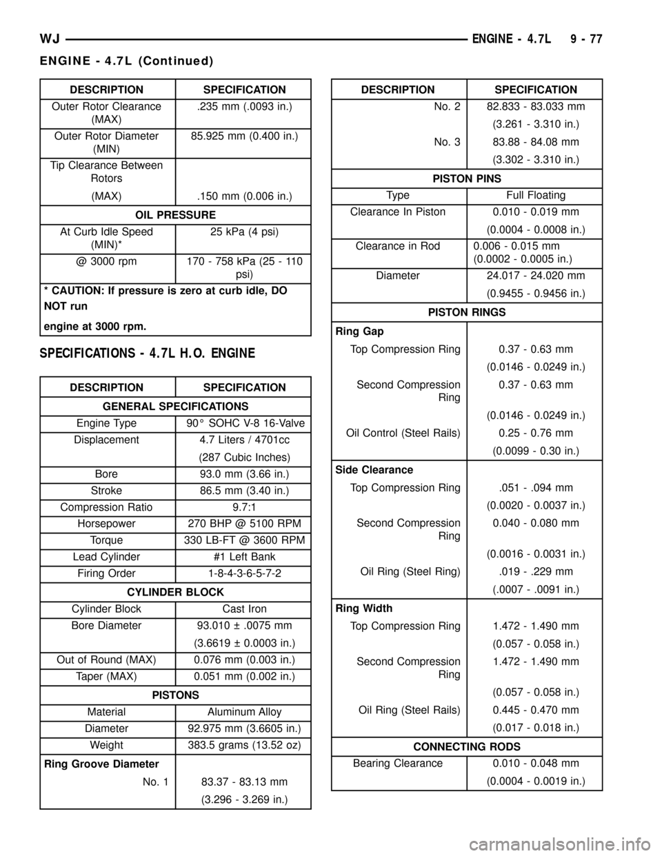
DESCRIPTION SPECIFICATION
Outer Rotor Clearance
(MAX).235 mm (.0093 in.)
Outer Rotor Diameter
(MIN)85.925 mm (0.400 in.)
Tip Clearance Between
Rotors
(MAX) .150 mm (0.006 in.)
OIL PRESSURE
At Curb Idle Speed
(MIN)*25 kPa (4 psi)
@ 3000 rpm 170 - 758 kPa (25 - 110
psi)
* CAUTION: If pressure is zero at curb idle, DO
NOT run
engine at 3000 rpm.
SPECIFICATIONS - 4.7L H.O. ENGINE
DESCRIPTION SPECIFICATION
GENERAL SPECIFICATIONS
Engine Type 90É SOHC V-8 16-Valve
Displacement 4.7 Liters / 4701cc
(287 Cubic Inches)
Bore 93.0 mm (3.66 in.)
Stroke 86.5 mm (3.40 in.)
Compression Ratio 9.7:1
Horsepower 270 BHP @ 5100 RPM
Torque 330 LB-FT @ 3600 RPM
Lead Cylinder #1 Left Bank
Firing Order 1-8-4-3-6-5-7-2
CYLINDER BLOCK
Cylinder Block Cast Iron
Bore Diameter 93.010 .0075 mm
(3.6619 0.0003 in.)
Out of Round (MAX) 0.076 mm (0.003 in.)
Taper (MAX) 0.051 mm (0.002 in.)
PISTONS
Material Aluminum Alloy
Diameter 92.975 mm (3.6605 in.)
Weight 383.5 grams (13.52 oz)
Ring Groove Diameter
No. 1 83.37 - 83.13 mm
(3.296 - 3.269 in.)
DESCRIPTION SPECIFICATION
No. 2 82.833 - 83.033 mm
(3.261 - 3.310 in.)
No. 3 83.88 - 84.08 mm
(3.302 - 3.310 in.)
PISTON PINS
Type Full Floating
Clearance In Piston 0.010 - 0.019 mm
(0.0004 - 0.0008 in.)
Clearance in Rod 0.006 - 0.015 mm
(0.0002 - 0.0005 in.)
Diameter 24.017 - 24.020 mm
(0.9455 - 0.9456 in.)
PISTON RINGS
Ring Gap
Top Compression Ring 0.37 - 0.63 mm
(0.0146 - 0.0249 in.)
Second Compression
Ring0.37 - 0.63 mm
(0.0146 - 0.0249 in.)
Oil Control (Steel Rails) 0.25 - 0.76 mm
(0.0099 - 0.30 in.)
Side Clearance
Top Compression Ring .051 - .094 mm
(0.0020 - 0.0037 in.)
Second Compression
Ring0.040 - 0.080 mm
(0.0016 - 0.0031 in.)
Oil Ring (Steel Ring) .019 - .229 mm
(.0007 - .0091 in.)
Ring Width
Top Compression Ring 1.472 - 1.490 mm
(0.057 - 0.058 in.)
Second Compression
Ring1.472 - 1.490 mm
(0.057 - 0.058 in.)
Oil Ring (Steel Rails) 0.445 - 0.470 mm
(0.017 - 0.018 in.)
CONNECTING RODS
Bearing Clearance 0.010 - 0.048 mm
(0.0004 - 0.0019 in.)
WJENGINE - 4.7L 9 - 77
ENGINE - 4.7L (Continued)
Page 1321 of 2199
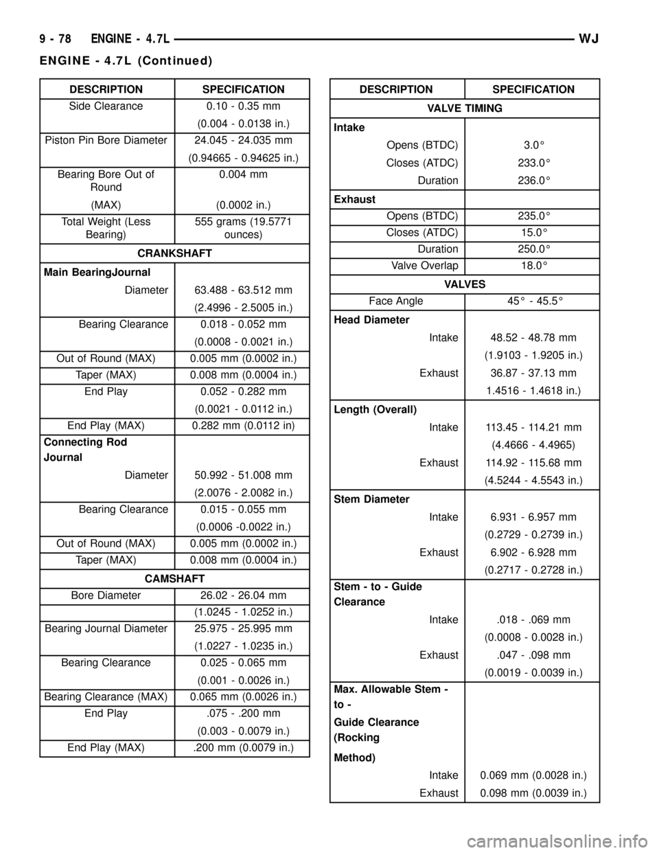
DESCRIPTION SPECIFICATION
Side Clearance 0.10 - 0.35 mm
(0.004 - 0.0138 in.)
Piston Pin Bore Diameter 24.045 - 24.035 mm
(0.94665 - 0.94625 in.)
Bearing Bore Out of
Round0.004 mm
(MAX) (0.0002 in.)
Total Weight (Less
Bearing)555 grams (19.5771
ounces)
CRANKSHAFT
Main BearingJournal
Diameter 63.488 - 63.512 mm
(2.4996 - 2.5005 in.)
Bearing Clearance 0.018 - 0.052 mm
(0.0008 - 0.0021 in.)
Out of Round (MAX) 0.005 mm (0.0002 in.)
Taper (MAX) 0.008 mm (0.0004 in.)
End Play 0.052 - 0.282 mm
(0.0021 - 0.0112 in.)
End Play (MAX) 0.282 mm (0.0112 in)
Connecting Rod
Journal
Diameter 50.992 - 51.008 mm
(2.0076 - 2.0082 in.)
Bearing Clearance 0.015 - 0.055 mm
(0.0006 -0.0022 in.)
Out of Round (MAX) 0.005 mm (0.0002 in.)
Taper (MAX) 0.008 mm (0.0004 in.)
CAMSHAFT
Bore Diameter 26.02 - 26.04 mm
(1.0245 - 1.0252 in.)
Bearing Journal Diameter 25.975 - 25.995 mm
(1.0227 - 1.0235 in.)
Bearing Clearance 0.025 - 0.065 mm
(0.001 - 0.0026 in.)
Bearing Clearance (MAX) 0.065 mm (0.0026 in.)
End Play .075 - .200 mm
(0.003 - 0.0079 in.)
End Play (MAX) .200 mm (0.0079 in.)DESCRIPTION SPECIFICATION
VALVE TIMING
Intake
Opens (BTDC) 3.0É
Closes (ATDC) 233.0É
Duration 236.0É
Exhaust
Opens (BTDC) 235.0É
Closes (ATDC) 15.0É
Duration 250.0É
Valve Overlap 18.0É
VA LV E S
Face Angle 45É - 45.5É
Head Diameter
Intake 48.52 - 48.78 mm
(1.9103 - 1.9205 in.)
Exhaust 36.87 - 37.13 mm
1.4516 - 1.4618 in.)
Length (Overall)
Intake 113.45 - 114.21 mm
(4.4666 - 4.4965)
Exhaust 114.92 - 115.68 mm
(4.5244 - 4.5543 in.)
Stem Diameter
Intake 6.931 - 6.957 mm
(0.2729 - 0.2739 in.)
Exhaust 6.902 - 6.928 mm
(0.2717 - 0.2728 in.)
Stem - to - Guide
Clearance
Intake .018 - .069 mm
(0.0008 - 0.0028 in.)
Exhaust .047 - .098 mm
(0.0019 - 0.0039 in.)
Max. Allowable Stem -
to -
Guide Clearance
(Rocking
Method)
Intake 0.069 mm (0.0028 in.)
Exhaust 0.098 mm (0.0039 in.)
9 - 78 ENGINE - 4.7LWJ
ENGINE - 4.7L (Continued)
Page 1322 of 2199
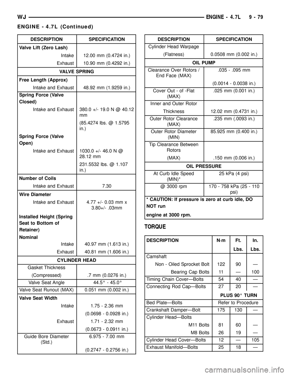
DESCRIPTION SPECIFICATION
Valve Lift (Zero Lash)
Intake 12.00 mm (0.4724 in.)
Exhaust 10.90 mm (0.4292 in.)
VALVE SPRING
Free Length (Approx)
Intake and Exhaust 48.92 mm (1.9259 in.)
Spring Force (Valve
Closed)
Intake and Exhaust 380.0 +/- 19.0 N @ 40.12
mm
(85.4274 lbs. @ 1.5795
in.)
Spring Force (Valve
Open)
Intake and Exhaust 1030.0 +/- 46.0 N @
28.12 mm
231.5532 lbs. @ 1.107
in.)
Number of Coils
Intake and Exhaust 7.30
Wire Diameter
Intake and Exhaust 4.77 +/- 0.03 mm x
3.80+/- .03mm
Installed Height (Spring
Seat to Bottom of
Retainer)
Nominal
Intake 40.97 mm (1.613 in.)
Exhaust 40.81 mm (1.606 in.)
CYLINDER HEAD
Gasket Thickness
(Compressed) .7 mm (0.0276 in.)
Valve Seat Angle 44.5É - 45.0É
Valve Seat Runout (MAX) 0.051 mm (0.002 in.)
Valve Seat Width
Intake 1.75 - 2.36 mm
(0.0698 - 0.0928 in.)
Exhaust 1.71 - 2.32 mm
(0.0673 - 0.0911 in.)
Guide Bore Diameter
(Std.)6.975 - 7.00 mm
(0.2747 - 0.2756 in.)DESCRIPTION SPECIFICATION
Cylinder Head Warpage
(Flatness) 0.0508 mm (0.002 in.)
OIL PUMP
Clearance Over Rotors /
End Face (MAX).035 - .095 mm
(0.0014 - 0.0038 in.)
Cover Out - of -Flat
(MAX).025 mm (0.001 in.)
Inner and Outer Rotor
Thickness 12.02 mm (0.4731 in.)
Outer Rotor Clearance
(MAX).235 mm (.0093 in.)
Outer Rotor Diameter
(MIN)85.925 mm (0.400 in.)
Tip Clearance Between
Rotors
(MAX) .150 mm (0.006 in.)
OIL PRESSURE
At Curb Idle Speed
(MIN)*25 kPa (4 psi)
@ 3000 rpm 170 - 758 kPa (25 - 110
psi)
* CAUTION: If pressure is zero at curb idle, DO
NOT run
engine at 3000 rpm.
TORQUE
DESCRIPTION N´m Ft. In.
Lbs. Lbs.
Camshaft
Non - Oiled Sprocket Bolt 122 90 Ð
Bearing Cap Bolts 11 Ð 100
Timing Chain CoverÐBolts 54 40 Ð
Connecting Rod CapÐBolts 27 20 Ð
PLUS 90É TURN
Bed PlateÐBolts Refer to Procedure
Crankshaft DamperÐBolt 175 130 Ð
Cylinder HeadÐBolts
M11 Bolts 81 60 Ð
M8 Bolts 26 19 Ð
Cylinder Head CoverÐBolts 12 Ð 105
Exhaust ManifoldÐBolts 25 18 Ð
WJENGINE - 4.7L 9 - 79
ENGINE - 4.7L (Continued)
Page 1324 of 2199
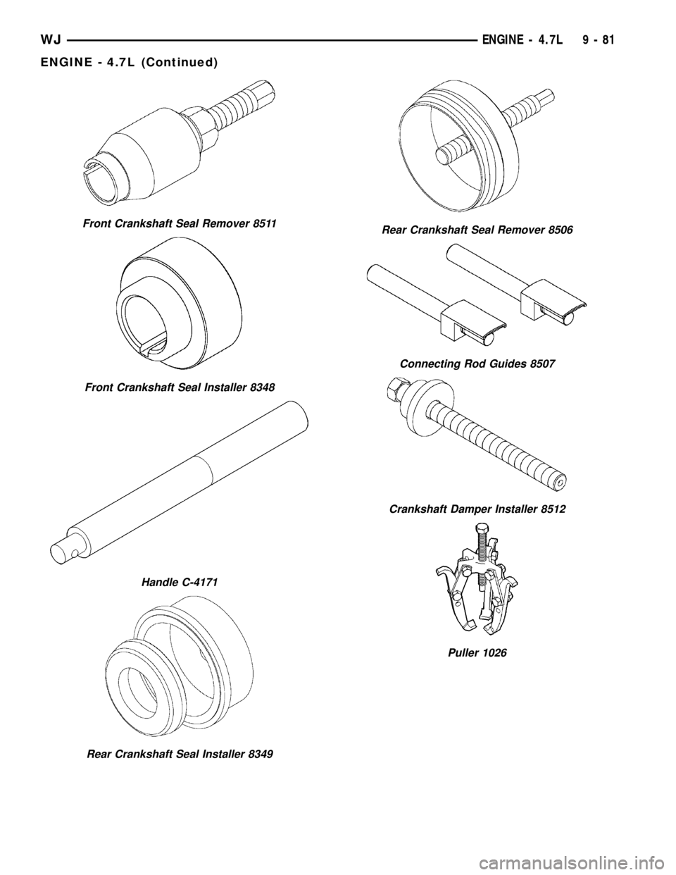
Front Crankshaft Seal Remover 8511
Front Crankshaft Seal Installer 8348
Handle C-4171
Rear Crankshaft Seal Installer 8349
Rear Crankshaft Seal Remover 8506
Connecting Rod Guides 8507
Crankshaft Damper Installer 8512
Puller 1026
WJENGINE - 4.7L 9 - 81
ENGINE - 4.7L (Continued)
Page 1352 of 2199
free cloth to check that the bore is clean. Oil the
bores after cleaning to prevent rusting.
CLEANING
Thoroughly clean the oil pan and engine block gas-
ket surfaces.
Use compressed air to clean out:
²The galley at the oil filter adaptor hole.
²The front and rear oil galley holes.
²The feed holes for the crankshaft main bearings.
Once the block has been completely cleaned, apply
Loctite PST pipe sealant with Teflon 592 to the
threads of the front and rear oil galley plugs. Tighten
the plugs to 34 N´m (25 ft. lbs.) torque.
INSPECTION
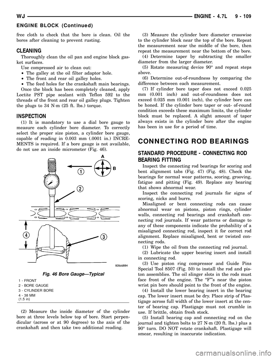
(1) It is mandatory to use a dial bore gauge to
measure each cylinder bore diameter. To correctly
select the proper size piston, a cylinder bore gauge,
capable of reading in 0.003 mm (.0001 in.) INCRE-
MENTS is required. If a bore gauge is not available,
do not use an inside micrometer (Fig. 46).
(2) Measure the inside diameter of the cylinder
bore at three levels below top of bore. Start perpen-
dicular (across or at 90 degrees) to the axis of the
crankshaft and then take two additional reading.(3) Measure the cylinder bore diameter crosswise
to the cylinder block near the top of the bore. Repeat
the measurement near the middle of the bore, then
repeat the measurement near the bottom of the bore.
(4) Determine taper by subtracting the smaller
diameter from the larger diameter.
(5) Rotate measuring device 90É and repeat steps
above.
(6) Determine out-of-roundness by comparing the
difference between each measurement.
(7) If cylinder bore taper does not exceed 0.025
mm (0.001 inch) and out-of-roundness does not
exceed 0.025 mm (0.001 inch), the cylinder bore can
be honed. If the cylinder bore taper or out- of-round
condition exceeds these maximum limits, the cylinder
block must be replaced. A slight amount of taper
always exists in the cylinder bore after the engine
has been in use for a period of time.
CONNECTING ROD BEARINGS
STANDARD PROCEDURE - CONNECTING ROD
BEARING FITTING
Inspect the connecting rod bearings for scoring and
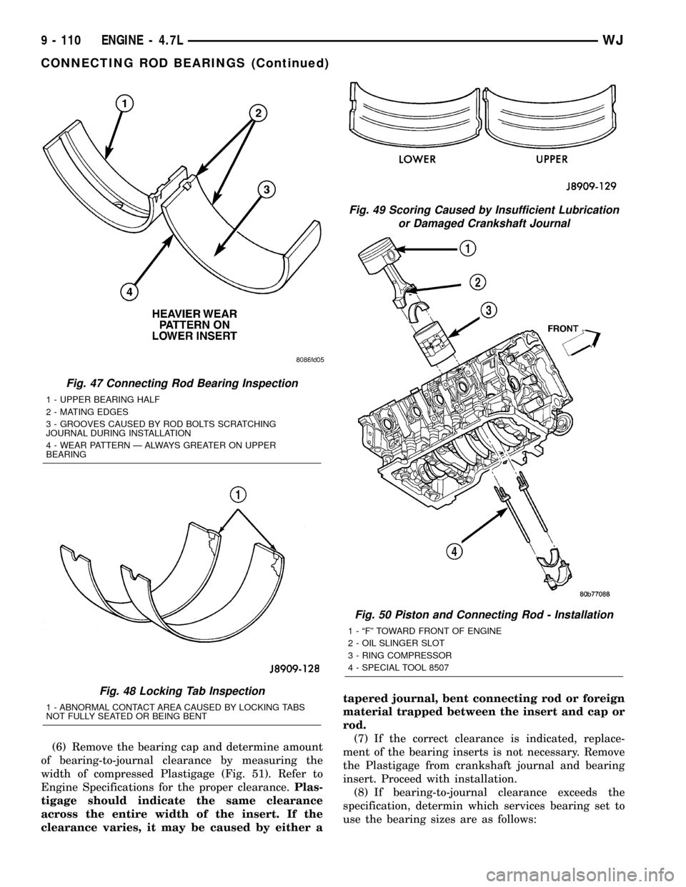
bent alignment tabs (Fig. 47) (Fig. 48). Check the
bearings for normal wear patterns, scoring, grooving,
fatigue and pitting (Fig. 49). Replace any bearing
that shows abnormal wear.
Inspect the connecting rod journals for signs of
scoring, nicks and burrs.
Misaligned or bent connecting rods can cause
abnormal wear on pistons, piston rings, cylinder
walls, connecting rod bearings and crankshaft con-
necting rod journals. If wear patterns or damage to
any of these components indicate the probability of a
misaligned connecting rod, inspect it for correct rod
alignment. Replace misaligned, bent or twisted con-
necting rods.
(1) Wipe the oil from the connecting rod journal.
(2) Lubricate the upper bearing insert and install
in connecting rod.
(3) Use piston ring compressor and Guide Pins
Special Tool 8507 (Fig. 50) to install the rod and pis-
ton assemblies. The oil slinger slots in the rods must
face front of the engine. The ªFº's near the piston
wrist pin bore should point to the front of the engine.
(4) Install the lower bearing insert in the bearing
cap. The lower insert must be dry. Place strip of Plas-
tigage across full width of the lower insert at the cen-
ter of bearing cap. Plastigage must not crumble in
use. If brittle, obtain fresh stock.
(5) Install bearing cap and connecting rod on the
journal and tighten bolts to 27 N´m (20 ft. lbs.) plus a
90É turn. DO NOT rotate crankshaft. Plastigage will
smear, resulting in inaccurate indication.
Fig. 46 Bore GaugeÐTypical
1 - FRONT
2 - BORE GAUGE
3 - CYLINDER BORE
4-38MM
(1.5 in)
WJENGINE - 4.7L 9 - 109
ENGINE BLOCK (Continued)
Page 1353 of 2199
(6) Remove the bearing cap and determine amount
of bearing-to-journal clearance by measuring the
width of compressed Plastigage (Fig. 51). Refer to
Engine Specifications for the proper clearance.Plas-
tigage should indicate the same clearance
across the entire width of the insert. If the
clearance varies, it may be caused by either atapered journal, bent connecting rod or foreign
material trapped between the insert and cap or
rod.
(7) If the correct clearance is indicated, replace-
ment of the bearing inserts is not necessary. Remove
the Plastigage from crankshaft journal and bearing
insert. Proceed with installation.
(8) If bearing-to-journal clearance exceeds the
specification, determin which services bearing set to
use the bearing sizes are as follows:
Fig. 47 Connecting Rod Bearing Inspection
1 - UPPER BEARING HALF
2 - MATING EDGES
3 - GROOVES CAUSED BY ROD BOLTS SCRATCHING
JOURNAL DURING INSTALLATION
4 - WEAR PATTERN Ð ALWAYS GREATER ON UPPER
BEARING
Fig. 48 Locking Tab Inspection
1 - ABNORMAL CONTACT AREA CAUSED BY LOCKING TABS
NOT FULLY SEATED OR BEING BENT
Fig. 49 Scoring Caused by Insufficient Lubrication
or Damaged Crankshaft Journal
Fig. 50 Piston and Connecting Rod - Installation
1 - ªFº TOWARD FRONT OF ENGINE
2 - OIL SLINGER SLOT
3 - RING COMPRESSOR
4 - SPECIAL TOOL 8507
9 - 110 ENGINE - 4.7LWJ
CONNECTING ROD BEARINGS (Continued)