grill JEEP GRAND CHEROKEE 2002 WJ / 2.G Owner's Manual
[x] Cancel search | Manufacturer: JEEP, Model Year: 2002, Model line: GRAND CHEROKEE, Model: JEEP GRAND CHEROKEE 2002 WJ / 2.GPages: 2199, PDF Size: 76.01 MB
Page 624 of 2199
crank arm, the two wiper linkage members, and the
two wiper pivots mechanically convert the rotary out-
put of the wiper motor to the back and forth wiping
motion of the wiper arms and blades on the glass.
REMOVAL
(1) Disconnect and isolate the battery negative
cable.
(2) Remove the front wiper arms from the wiper
pivots. (Refer to 8 - ELECTRICAL/FRONT WIPERS/
WASHERS/FRONT WIPER ARMS - REMOVAL).
(3) Unlatch and open the hood.
(4) Remove the hood to plenum seal from the for-
ward flanges of the cowl grille cover and the plenum
panel.
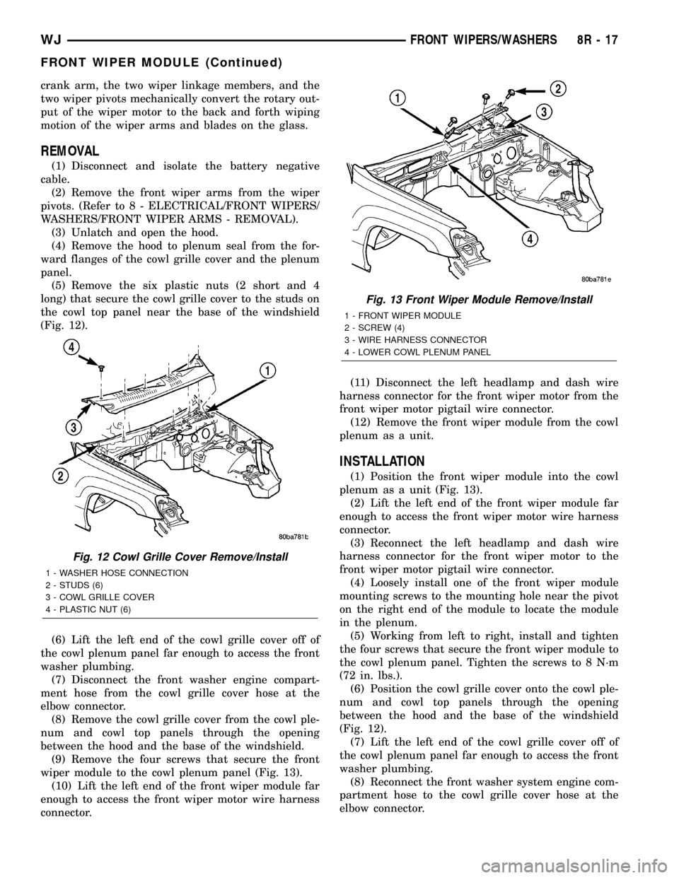
(5) Remove the six plastic nuts (2 short and 4
long) that secure the cowl grille cover to the studs on
the cowl top panel near the base of the windshield
(Fig. 12).
(6) Lift the left end of the cowl grille cover off of
the cowl plenum panel far enough to access the front
washer plumbing.
(7) Disconnect the front washer engine compart-
ment hose from the cowl grille cover hose at the
elbow connector.
(8) Remove the cowl grille cover from the cowl ple-
num and cowl top panels through the opening
between the hood and the base of the windshield.
(9) Remove the four screws that secure the front
wiper module to the cowl plenum panel (Fig. 13).
(10) Lift the left end of the front wiper module far
enough to access the front wiper motor wire harness
connector.(11) Disconnect the left headlamp and dash wire
harness connector for the front wiper motor from the
front wiper motor pigtail wire connector.
(12) Remove the front wiper module from the cowl
plenum as a unit.
INSTALLATION
(1) Position the front wiper module into the cowl
plenum as a unit (Fig. 13).
(2) Lift the left end of the front wiper module far
enough to access the front wiper motor wire harness
connector.
(3) Reconnect the left headlamp and dash wire
harness connector for the front wiper motor to the
front wiper motor pigtail wire connector.
(4) Loosely install one of the front wiper module
mounting screws to the mounting hole near the pivot
on the right end of the module to locate the module
in the plenum.
(5) Working from left to right, install and tighten
the four screws that secure the front wiper module to
the cowl plenum panel. Tighten the screws to 8 N´m
(72 in. lbs.).
(6) Position the cowl grille cover onto the cowl ple-
num and cowl top panels through the opening
between the hood and the base of the windshield
(Fig. 12).
(7) Lift the left end of the cowl grille cover off of
the cowl plenum panel far enough to access the front
washer plumbing.
(8) Reconnect the front washer system engine com-
partment hose to the cowl grille cover hose at the
elbow connector.
Fig. 12 Cowl Grille Cover Remove/Install
1 - WASHER HOSE CONNECTION
2 - STUDS (6)
3 - COWL GRILLE COVER
4 - PLASTIC NUT (6)
Fig. 13 Front Wiper Module Remove/Install
1 - FRONT WIPER MODULE
2 - SCREW (4)
3 - WIRE HARNESS CONNECTOR
4 - LOWER COWL PLENUM PANEL
WJFRONT WIPERS/WASHERS 8R - 17
FRONT WIPER MODULE (Continued)
Page 625 of 2199
(9) Install the six plastic nuts that secure the cowl
grille cover to the studs on the cowl top panel near
the base of the windshield. These nuts are to be
installed by pushing them onto the studs in the fol-
lowing sequence:
(a) First, install the short nuts to the third stud
from the right, then the second stud from the left.
(b) Next, install long nuts to the right outboard
stud, then the left outboard stud.
(c) Finally, install the two remaining long nuts
to the third stud from the left, then the second
stud from the right.
(10) Starting at the ends and working toward the
center, push the hood to plenum seal onto the for-
ward flanges of the cowl grille cover and the plenum
panel.
(11) Close and latch the hood.
(12) Reinstall the wiper arms onto the wiper piv-
ots. (Refer to 8 - ELECTRICAL/FRONT WIPERS/
WASHERS/FRONT WIPER ARMS -
INSTALLATION).
(13) Reconnect the battery negative cable.
RAIN SENSOR MODULE
DESCRIPTION
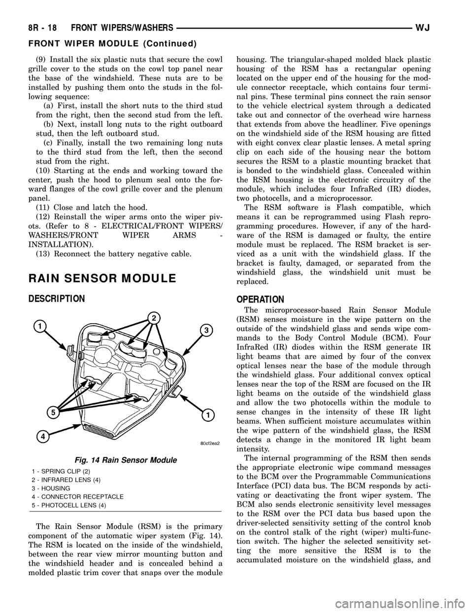
The Rain Sensor Module (RSM) is the primary
component of the automatic wiper system (Fig. 14).
The RSM is located on the inside of the windshield,
between the rear view mirror mounting button and
the windshield header and is concealed behind a
molded plastic trim cover that snaps over the modulehousing. The triangular-shaped molded black plastic
housing of the RSM has a rectangular opening
located on the upper end of the housing for the mod-
ule connector receptacle, which contains four termi-
nal pins. These terminal pins connect the rain sensor
to the vehicle electrical system through a dedicated
take out and connector of the overhead wire harness
that extends from above the headliner. Five openings
on the windshield side of the RSM housing are fitted
with eight convex clear plastic lenses. A metal spring
clip on each side of the housing near the bottom
secures the RSM to a plastic mounting bracket that
is bonded to the windshield glass. Concealed within
the RSM housing is the electronic circuitry of the
module, which includes four InfraRed (IR) diodes,
two photocells, and a microprocessor.
The RSM software is Flash compatible, which
means it can be reprogrammed using Flash repro-
gramming procedures. However, if any of the hard-
ware of the RSM is damaged or faulty, the entire
module must be replaced. The RSM bracket is ser-
viced as a unit with the windshield glass. If the
bracket is faulty, damaged, or separated from the
windshield glass, the windshield unit must be
replaced.
OPERATION
The microprocessor-based Rain Sensor Module
(RSM) senses moisture in the wipe pattern on the
outside of the windshield glass and sends wipe com-
mands to the Body Control Module (BCM). Four
InfraRed (IR) diodes within the RSM generate IR
light beams that are aimed by four of the convex
optical lenses near the base of the module through
the windshield glass. Four additional convex optical
lenses near the top of the RSM are focused on the IR
light beams on the outside of the windshield glass
and allow the two photocells within the module to
sense changes in the intensity of these IR light
beams. When sufficient moisture accumulates within
the wipe pattern of the windshield glass, the RSM
detects a change in the monitored IR light beam
intensity.
The internal programming of the RSM then sends
the appropriate electronic wipe command messages
to the BCM over the Programmable Communications
Interface (PCI) data bus. The BCM responds by acti-
vating or deactivating the front wiper system. The
BCM also sends electronic sensitivity level messages
to the RSM over the PCI data bus based upon the
driver-selected sensitivity setting of the control knob
on the control stalk of the right (wiper) multi-func-
tion switch. The higher the selected sensitivity set-
ting the more sensitive the RSM is to the
accumulated moisture on the windshield glass, and
Fig. 14 Rain Sensor Module
1 - SPRING CLIP (2)
2 - INFRARED LENS (4)
3 - HOUSING
4 - CONNECTOR RECEPTACLE
5 - PHOTOCELL LENS (4)
8R - 18 FRONT WIPERS/WASHERSWJ
FRONT WIPER MODULE (Continued)
Page 1274 of 2199
REMOVAL
REMOVAL - CAMSHAFT BEARINGS
The camshaft rotates within four steel-shelled,
babbitt-lined bearings that are pressed into the cyl-
inder block and then line reamed. The camshaft
bearing bores and bearing diameters are not the
same size. They are stepped down in 0.254 mm
(0.010 inch) increments from the front bearing (larg-
est) to the rear bearing (smallest). This permits eas-
ier removal and installation of the camshaft. The
camshaft bearings are pressure lubricated. Camshaft
end play is maintained by the thrust plate.
(1) Remove the camshaft (Refer to 9 - ENGINE/
ENGINE BLOCK/CAMSHAFT & BEARINGS (IN
BLOCK) - REMOVAL).
NOTE: It is not advisable to attempt to replace cam-
shaft bearings unless special removal and installa-
tion tools are available, such as recommended tool
8544 Camshaft Bushing Remover Installer.
(2) Using Special tool 8544 Camshaft Bushing
Remover Installer, remove the camshaft bearings.
REMOVAL - CAMSHAFT
WARNING: THE COOLANT IN A RECENTLY OPER-
ATED ENGINE IS HOT AND PRESSURIZED.RELEASE THE PRESSURE BEFORE REMOVING
THE DRAIN COCK, CAP AND DRAIN PLUGS.
(1) Disconnect negative cable from battery.
(2) Drain the cooling system (Refer to 7 - COOL-
ING - STANDARD PROCEDURE).
(3) Remove the radiator (Refer to 7 - COOLING/
ENGINE/RADIATOR - REMOVAL) and condenser
(Refer to 24 - HEATING & AIR CONDITIONING/
PLUMBING/A/C CONDENSER - REMOVAL), if
equipped with A/C.
(4) Remove the engine cylinder head cover (Refer
to 9 - ENGINE/CYLINDER HEAD/CYLINDER
HEAD COVER(S) - REMOVAL).
(5) Remove the rocker arms, bridges and pivots
(Refer to 9 - ENGINE/CYLINDER HEAD/ROCKER
ARM / ADJUSTER ASSY - REMOVAL).
(6) Remove the push rods.
(7) Remove the engine cylinder head and gasket
(Refer to 9 - ENGINE/CYLINDER HEAD - REMOV-
AL).
(8) Remove the hydraulic valve tappets from the
engine cylinder block (Refer to 9 - ENGINE/ENGINE
BLOCK/HYDRAULIC LIFTERS (CAM IN BLOCK) -
REMOVAL).
(9) Remove the vibration damper (Refer to 9 -
ENGINE/ENGINE BLOCK/VIBRATION DAMPER -
REMOVAL).
(10) Remove the timing case cover (Refer to 9 -
ENGINE/VALVE TIMING/TIMING BELT / CHAIN
COVER(S) - REMOVAL).
(11) Rotate the crankshaft until the crankshaft
sprocket timing mark is aligned on centerline with
the camshaft sprocket timing mark (Fig. 32).
(12) Remove the timing chain and sprockets (Refer
to 9 - ENGINE/VALVE TIMING/TIMING BELT/
CHAIN AND SPROCKETS - REMOVAL).
(13) Remove the front bumper and/or grille, as
required.
(14) Remove the two thrust plate retaining screws,
thrust plate and camshaft (Fig. 31).
INSPECTION
INSPECTION - CAMSHAFT BEARINGS
(1) Inspect the bearing journals for uneven wear
pattern or finish.
(2) Inspect the bearings for wear.
INSPECTION - CAMSHAFT
(1) Inspect the cam lobes for wear.
(2) Inspect the camshaft position sensor drive gear
for wear.
(3) If the camshaft appears to have been rubbing
against the thrust washer, examine the oil pressure
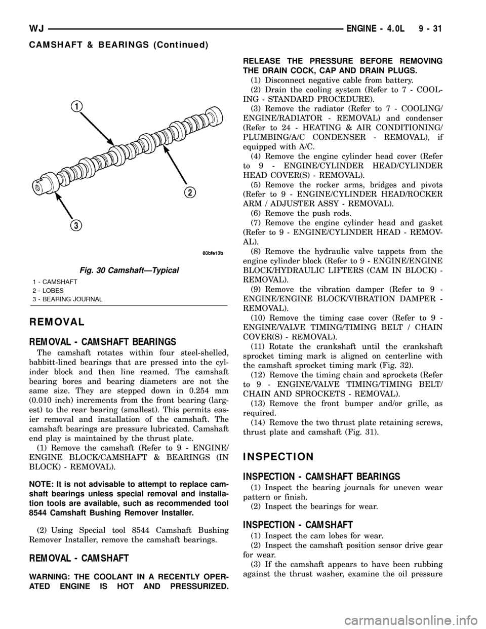
Fig. 30 CamshaftÐTypical
1 - CAMSHAFT
2 - LOBES
3 - BEARING JOURNAL
WJENGINE - 4.0L 9 - 31
CAMSHAFT & BEARINGS (Continued)
Page 1276 of 2199
(16) Install the serpentine drive belt (Refer to 7 -
COOLING/ACCESSORY DRIVE/DRIVE BELTS -
INSTALLATION).
NOTE: During installation, lubricate the hydraulic
valve tappets and all valve components with
MoparTEngine Oil Supplement, or equivalent. TheMoparTEngine Oil Supplement, or equivalent must
remain with the engine oil for at least 1609 km
(1,000 miles). The oil supplement need not be
drained until the next scheduled oil change.
(17) Install the radiator (Refer to 7 - COOLING/
ENGINE/RADIATOR - INSTALLATION).
(18) Check the ignition timing and adjust as nec-
essary.
(19) Install the grille and bumper, if removed.
(20) Connect negative cable to battery.
CONNECTING ROD BEARINGS
STANDARD PROCEDURE - FITTING
CONNECTING ROD BEARINGS
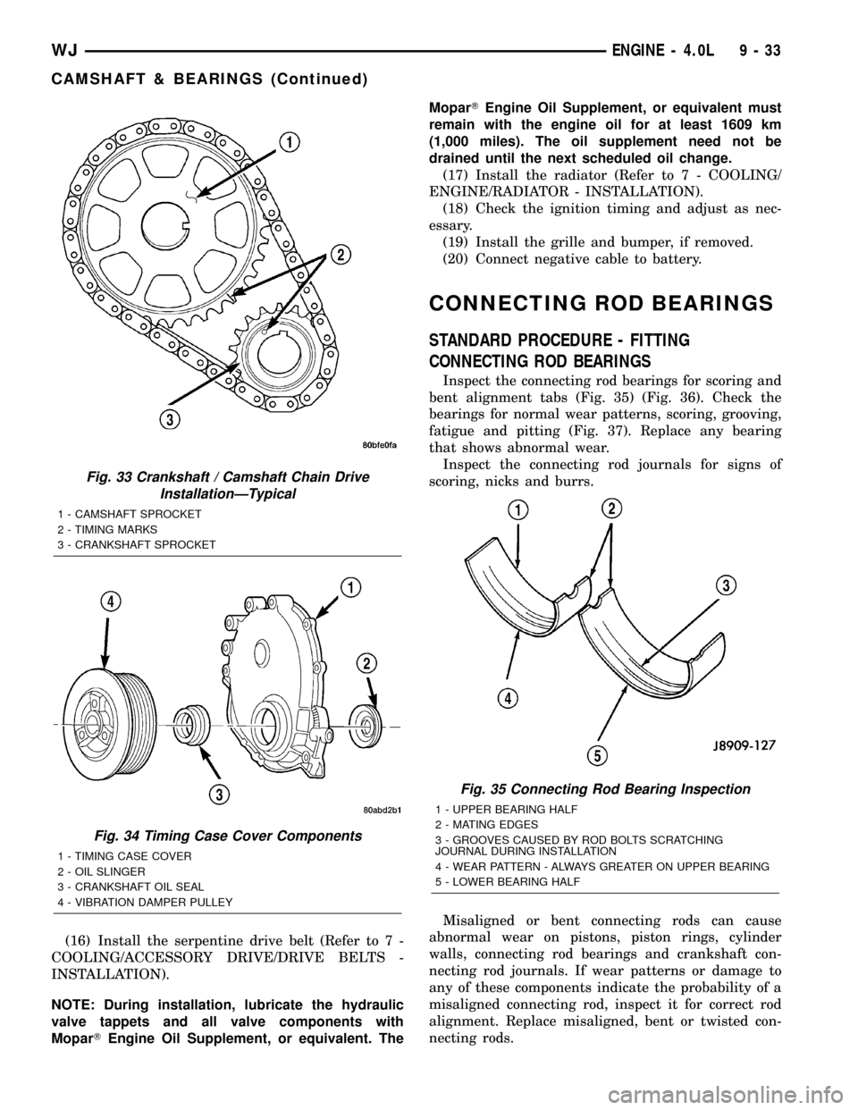
Inspect the connecting rod bearings for scoring and
bent alignment tabs (Fig. 35) (Fig. 36). Check the
bearings for normal wear patterns, scoring, grooving,
fatigue and pitting (Fig. 37). Replace any bearing
that shows abnormal wear.
Inspect the connecting rod journals for signs of
scoring, nicks and burrs.
Misaligned or bent connecting rods can cause
abnormal wear on pistons, piston rings, cylinder
walls, connecting rod bearings and crankshaft con-
necting rod journals. If wear patterns or damage to
any of these components indicate the probability of a
misaligned connecting rod, inspect it for correct rod
alignment. Replace misaligned, bent or twisted con-
necting rods.
Fig. 33 Crankshaft / Camshaft Chain Drive
InstallationÐTypical
1 - CAMSHAFT SPROCKET
2 - TIMING MARKS
3 - CRANKSHAFT SPROCKET
Fig. 34 Timing Case Cover Components
1 - TIMING CASE COVER
2 - OIL SLINGER
3 - CRANKSHAFT OIL SEAL
4 - VIBRATION DAMPER PULLEY
Fig. 35 Connecting Rod Bearing Inspection
1 - UPPER BEARING HALF
2 - MATING EDGES
3 - GROOVES CAUSED BY ROD BOLTS SCRATCHING
JOURNAL DURING INSTALLATION
4 - WEAR PATTERN - ALWAYS GREATER ON UPPER BEARING
5 - LOWER BEARING HALF
WJENGINE - 4.0L 9 - 33
CAMSHAFT & BEARINGS (Continued)
Page 1412 of 2199
FRAME & BUMPERS
TABLE OF CONTENTS
page page
FRONT ABSORBER
REMOVAL.............................1
INSTALLATION..........................1
FRONT FASCIA
REMOVAL.............................1
INSTALLATION..........................1
REAR ABSORBER
REMOVAL.............................2
INSTALLATION..........................2
REAR FASCIA
REMOVAL.............................2
INSTALLATION..........................4
FRAME
SPECIFICATIONS
SPECIFICATIONS - TORQUE.............4
FRAME DIMENSIONS...................4
FRONT SKID PLATE
REMOVAL.............................7INSTALLATION..........................7
FRONT TOW HOOK
REMOVAL.............................7
INSTALLATION..........................7
FUEL TANK SKID PLATE
DESCRIPTION..........................7
REAR TOW HOOK
REMOVAL.............................7
INSTALLATION..........................7
TRAILER HITCH
REMOVAL.............................8
INSTALLATION..........................8
TRANSFER CASE SKID PLATE
REMOVAL.............................8
INSTALLATION..........................8
FRONT ABSORBER
REMOVAL
(1) Remove front fascia, refer to (Refer to 13 -
FRAMES & BUMPERS/BUMPERS/FRONT FASCIA
- REMOVAL).
(2) Remove the retainer attaching the absorber to
the fascia.
(3) Separate the absorber from the fascia.
INSTALLATION
(1) Position the absorber on the fascia.
(2) Install the retainer attaching the absorber to
the fascia.
(3) Install front fascia. Refer to (Refer to 13 -
FRAMES & BUMPERS/BUMPERS/FRONT FASCIA
- INSTALLATION).
FRONT FASCIA
REMOVAL
(1) Raise and support vehicle.
(2) Turn front wheels to access rivets and remove
plastic rivets attaching fascia to wheel liner.
(3) Remove bolts attaching fascia to fender (Fig. 1).(4) Remove plastic push pin fasteners attaching
front fascia to lower radiator crossmember splash
shield (Fig. 2).
(5) Disengage fog lamp connectors, if equipped.
(6) Remove screws attaching fascia/grille to upper
radiator crossmember (Fig. 3).
(7) Slide fascia forward to separate from vehicle.
INSTALLATION
(1) Slide fascia onto vehicle engaging fascia with
tabs on bottom of front fenders.
(2) Install screws attaching fascia/grille to upper
radiator crossmember (Fig. 3).
(3) Install bolts attaching fascia to fender (Fig. 1).
(4) Engage fog lamp connectors, if equipped.
(5) Install plastic rivets attaching fascia to wheel
liner.
(6) Install plastic push pin fasteners attaching
front fascia to lower radiator crossmember splash
shield (Fig. 2).
(7) Remove supports and lower vehicle.
WJFRAME & BUMPERS 13 - 1
Page 1453 of 2199
(8) Inspect system body grounds for loose or dirty
connections. Refer to Group 8, Wiring for ground
locations.
(9) Verify crankcase ventilation (CCV) operation.
Refer to Emission Control System for additional
information.
(10) Inspect all fuel line quick-connect fittings for
damage or leaks.
(11) Verify hose connections to all ports of vacuum
fittings on intake manifold, and for emission system
are tight and not leaking.
(12) Inspect accelerator cable, transmission throt-
tle cable (if equipped) and speed control cable connec-
tions (if equipped). Check their connections to
throttle body linkage for any binding or restrictions.
(13) Verify vacuum booster hose is firmly con-
nected to fitting on intake manifold. Also check con-
nection to brake vacuum booster.(14) Inspect air cleaner inlet and air cleaner ele-
ment for dirt or restrictions.
(15) Inspect radiator grille area, radiator fins and
air conditioning condenser for restrictions.
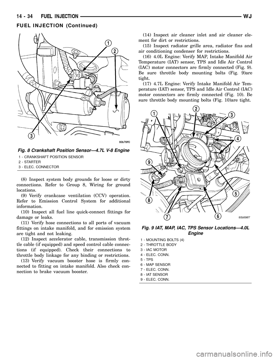
(16) 4.0L Engine: Verify MAP, Intake Manifold Air
Temperature (IAT) sensor, TPS and Idle Air Control
(IAC) motor connectors are firmly connected (Fig. 9).
Be sure throttle body mounting bolts (Fig. 9)are
tight.
(17) 4.7L Engine: Verify Intake Manifold Air Tem-
perature (IAT) sensor, TPS and Idle Air Control (IAC)
motor connectors are firmly connected (Fig. 10). Be
sure throttle body mounting bolts (Fig. 10)are tight.
Fig. 8 Crankshaft Position SensorÐ4.7L V-8 Engine
1 - CRANKSHAFT POSITION SENSOR
2-STARTER
3 - ELEC. CONNECTOR
Fig. 9 IAT, MAP, IAC, TPS Sensor LocationsÐ4.0L
Engine
1 - MOUNTING BOLTS (4)
2 - THROTTLE BODY
3 - IAC MOTOR
4 - ELEC. CONN.
5 - TPS
6 - MAP SENSOR
7 - ELEC. CONN.
8 - IAT SENSOR
9 - ELEC. CONN.
14 - 34 FUEL INJECTIONWJ
FUEL INJECTION (Continued)
Page 1513 of 2199
SPECIAL TOOLS
POWER STEERING PUMP
FLUID COOLER
DESCRIPTION
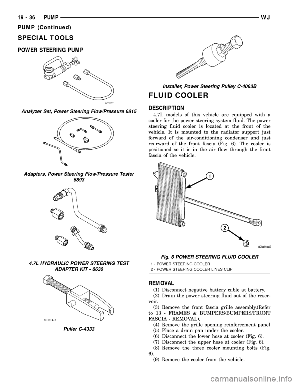
4.7L models of this vehicle are equipped with a
cooler for the power steering system fluid. The power
steering fluid cooler is located at the front of the
vehicle. It is mounted to the radiator support just
forward of the air-conditioning condenser and just
rearward of the front fascia (Fig. 6). The cooler is
positioned so it is in the air flow through the front
fascia of the vehicle.
REMOVAL
(1) Disconnect negative battery cable at battery.
(2) Drain the power steering fluid out of the reser-
voir.
(3) Remove the front fascia grille assembly,(Refer
to 13 - FRAMES & BUMPERS/BUMPERS/FRONT
FASCIA - REMOVAL).
(4) Remove the grille opening reinforcement panel
(5) Place a drain pan under the cooler.
(6) Disconnect the lower hose at cooler (Fig. 6).
(7) Disconnect the upper hose at cooler (Fig. 6).
(8) Remove the three cooler mounting bolts (Fig.
6).
(9) Remove the cooler from the vehicle.
Analyzer Set, Power Steering Flow/Pressure 6815
Adapters, Power Steering Flow/Pressure Tester
6893
4.7L HYDRAULIC POWER STEERING TEST
ADAPTER KIT - 8630
Puller C-4333
Installer, Power Steering Pulley C-4063B
Fig. 6 POWER STEERING FLUID COOLER
1 - POWER STEERING COOLER
2 - POWER STEERING COOLER LINES CLIP
19 - 36 PUMPWJ
PUMP (Continued)
Page 1514 of 2199
INSTALLATION
(1) Position and install the power steering cooler
to the vehicle.
(2) Install the three mounting bracket bolts (Fig.
6).
(3) Reconnect the upper hose at cooler (Fig. 6).
(4) Reconnect the lower hose at cooler (Fig. 6).
(5) Connect negative battery cable to battery.
(6) Refill the power steering fluid and bleed the
system,(Refer to 19 - STEERING/PUMP - STAN-
DARD PROCEDURE).
(7) Start engine and check for leaks.
(8) Install the grille opening reinforcement panel
(9) Install the front fascia grille,(Refer to 13 -
FRAMES & BUMPERS/BUMPERS/FRONT FASCIA
- INSTALLATION).
HOSES - 4.0L
DESCRIPTION
DESCRIPTION - PRESSURE LINE
The hose consists of two metal ends and rubber
center section that contains a tuning cable. The
pump end uses a quick connect fitting. Lubircation
must be used on the quick connect nut and o-ring
when installing.
DESCRIPTION - RETURN LINE
Power steering return line is a hose which is
clamped at the pump and the gear.
OPERATION
OPERATION - PRESSURE LINE
Power steering pressure line, is used to transfer
high pressure power steering fluid, from the power
steering pump to the power steering gear on the
4.0L. The 4.7L power steering pressure line, is used
to transfer high pressure power steering fluid, from
the power steering pump to the engine cooling fan
and the steering gear.
OPERATION - RETURN LINE
Power steering return line, is used to transfer low
pressure power steering fluid, from the power steer-
ing gear to the power steering pump.
REMOVAL
(1) Drain the power steering fluid from the reser-
voir.
(2) Remove the air box,(Refer to 9 - ENGINE/AIR
INTAKE SYSTEM/AIR CLEANER HOUSING -
REMOVAL).
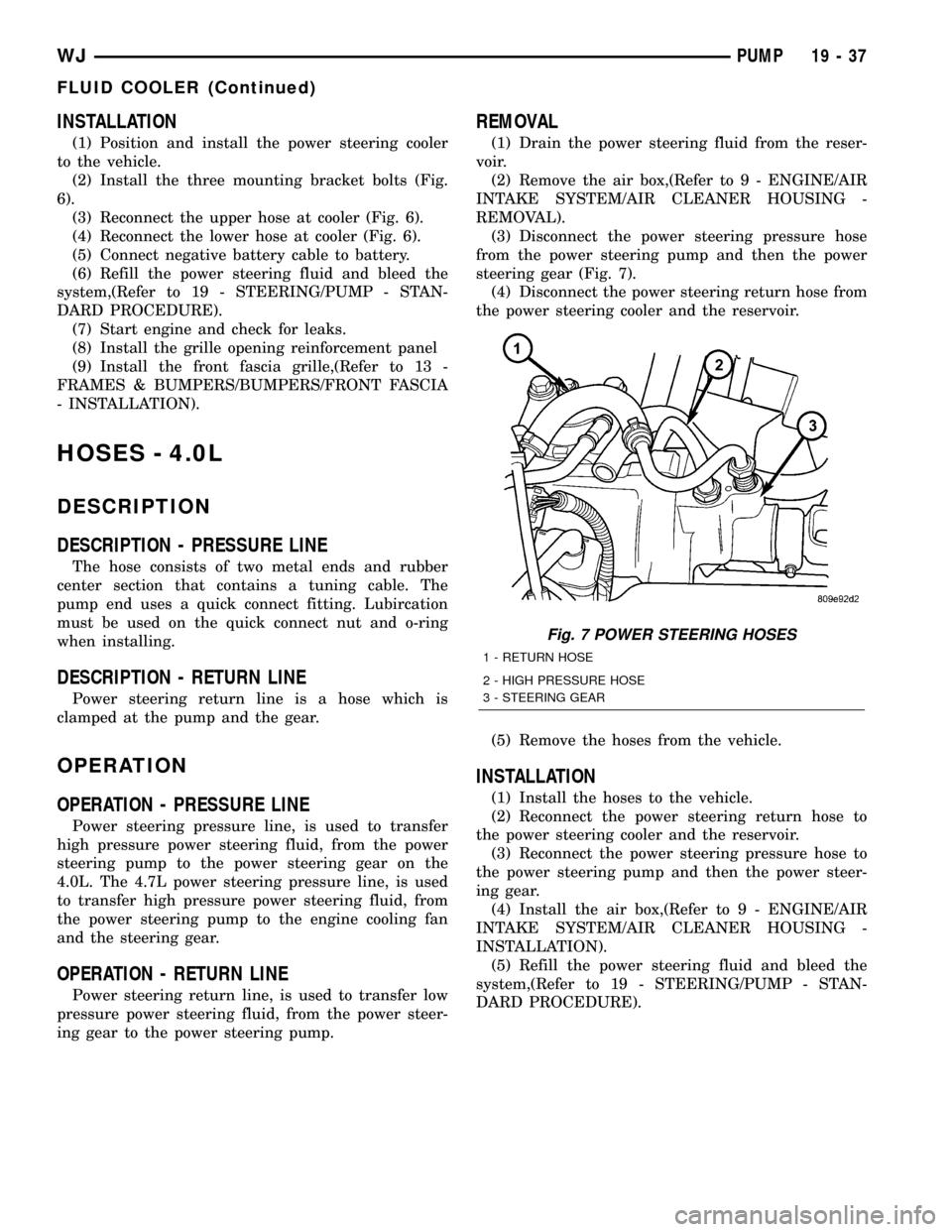
(3) Disconnect the power steering pressure hose
from the power steering pump and then the power
steering gear (Fig. 7).
(4) Disconnect the power steering return hose from
the power steering cooler and the reservoir.
(5) Remove the hoses from the vehicle.
INSTALLATION
(1) Install the hoses to the vehicle.
(2) Reconnect the power steering return hose to
the power steering cooler and the reservoir.
(3) Reconnect the power steering pressure hose to
the power steering pump and then the power steer-
ing gear.
(4) Install the air box,(Refer to 9 - ENGINE/AIR
INTAKE SYSTEM/AIR CLEANER HOUSING -
INSTALLATION).
(5) Refill the power steering fluid and bleed the
system,(Refer to 19 - STEERING/PUMP - STAN-
DARD PROCEDURE).
Fig. 7 POWER STEERING HOSES
1 - RETURN HOSE
2 - HIGH PRESSURE HOSE
3 - STEERING GEAR
WJPUMP 19 - 37
FLUID COOLER (Continued)
Page 1517 of 2199
(5) Disconnect the rubber hose from the power
steering reservoir (Fig. 12).
(6) Remove the hose from the vehicle.
REMOVAL - 3/8(GEAR OUTLET HOSE
(1) Drain the power steering fluid from the reser-
voir.
(2) Remove the air box,(Refer to 9 - ENGINE/AIR
INTAKE SYSTEM/AIR CLEANER HOUSING -
REMOVAL).
(3) Raise and support the vehicle.
(4) Disconnect the rubber hose from the steering
cooler inlet tube (Fig. 11).
(5) Disconnect the metal tube from the power
steering gear (Fig. 11).
(6) Remove the hose from the vehicle.
REMOVAL - INLET COOLER HOSE
(1) Disconnect negative battery cable at battery.
(2) Drain the power steering fluid out of the reser-
voir.
(3) Remove the air box,(Refer to 9 - ENGINE/AIR
INTAKE SYSTEM/AIR CLEANER HOUSING -
REMOVAL).
(4) Remove the front fascia grille assembly,(Refer
to 13 - FRAMES & BUMPERS/BUMPERS/FRONT
FASCIA - REMOVAL).
(5) Remove the grille opening reinforcement panel
(6) Place a drain pan under the cooler.
(7) Disconnect the lower hose at cooler (Fig. 6).
(8) Disconnect the cooler hose at the gear.
(9) Remove the bracket holding the cooler hoses
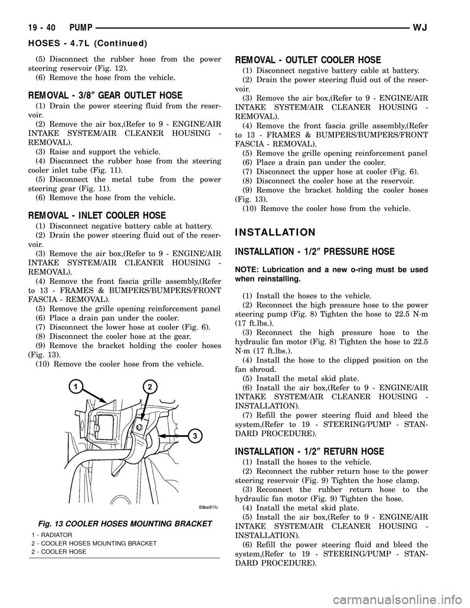
(Fig. 13).
(10) Remove the cooler hose from the vehicle.
REMOVAL - OUTLET COOLER HOSE
(1) Disconnect negative battery cable at battery.
(2) Drain the power steering fluid out of the reser-
voir.
(3) Remove the air box,(Refer to 9 - ENGINE/AIR
INTAKE SYSTEM/AIR CLEANER HOUSING -
REMOVAL).
(4) Remove the front fascia grille assembly,(Refer
to 13 - FRAMES & BUMPERS/BUMPERS/FRONT
FASCIA - REMOVAL).
(5) Remove the grille opening reinforcement panel
(6) Place a drain pan under the cooler.
(7) Disconnect the upper hose at cooler (Fig. 6).
(8) Disconnect the cooler hose at the reservoir.
(9) Remove the bracket holding the cooler hoses
(Fig. 13).
(10) Remove the cooler hose from the vehicle.
INSTALLATION
INSTALLATION - 1/2(PRESSURE HOSE
NOTE: Lubrication and a new o-ring must be used
when reinstalling.
(1) Install the hoses to the vehicle.
(2) Reconnect the high pressure hose to the power
steering pump (Fig. 8) Tighten the hose to 22.5 N´m
(17 ft.lbs.).
(3) Reconnect the high pressure hose to the
hydraulic fan motor (Fig. 8) Tighten the hose to 22.5
N´m (17 ft.lbs.).
(4) Install the hose to the clipped position on the
fan shroud.
(5) Install the metal skid plate.
(6) Install the air box,(Refer to 9 - ENGINE/AIR
INTAKE SYSTEM/AIR CLEANER HOUSING -
INSTALLATION).
(7) Refill the power steering fluid and bleed the
system,(Refer to 19 - STEERING/PUMP - STAN-
DARD PROCEDURE).
INSTALLATION - 1/2(RETURN HOSE
(1) Install the hoses to the vehicle.
(2) Reconnect the rubber return hose to the power
steering reservoir (Fig. 9) Tighten the hose clamp.
(3) Reconnect the rubber return hose to the
hydraulic fan motor (Fig. 9) Tighten the hose.
(4) Install the metal skid plate.
(5) Install the air box,(Refer to 9 - ENGINE/AIR
INTAKE SYSTEM/AIR CLEANER HOUSING -
INSTALLATION).
(6) Refill the power steering fluid and bleed the
system,(Refer to 19 - STEERING/PUMP - STAN-
DARD PROCEDURE).
Fig. 13 COOLER HOSES MOUNTING BRACKET
1 - RADIATOR
2 - COOLER HOSES MOUNTING BRACKET
2 - COOLER HOSE
19 - 40 PUMPWJ
HOSES - 4.7L (Continued)
Page 1518 of 2199
INSTALLATION - 3/8(PRESSURE HOSE
NOTE: Lubrication and a new o-ring must be used
when reinstalling.
(1) Install the hoses to the vehicle.
(2) Reconnect the high pressure hose to the
hydraulic fan motor (Fig. 10) Tighten the hose to
22.5 N´m (17 ft.lbs.).
(3) Reconnect the high pressure hose to the power
steering gear (Fig. 10) Tighten the hose to 22.5 N´m
(17 ft.lbs.).
(4) Install the hose to the clipped position on the
fan shroud.
(5) Install the metal skid plate.
(6) Install the air box,(Refer to 9 - ENGINE/AIR
INTAKE SYSTEM/AIR CLEANER HOUSING -
INSTALLATION).
(7) Refill the power steering fluid and bleed the
system,(Refer to 19 - STEERING/PUMP - STAN-
DARD PROCEDURE).
INSTALLATION - 3/8(RETURN HOSE
(1) Install the hoses to the vehicle.
(2) Reconnect the rubber hose to the steering
cooler outlet tube (Fig. 12) Tighten the hose clamp.
(3) Reconnect the rubber hose to the power steer-
ing reservoir (Fig. 12) Tighten the hose clamp.
(4) Install the air box,(Refer to 9 - ENGINE/AIR
INTAKE SYSTEM/AIR CLEANER HOUSING -
INSTALLATION).
(5) Refill the power steering fluid and bleed the
system,(Refer to 19 - STEERING/PUMP - STAN-
DARD PROCEDURE).
INSTALLATION - 3/8(GEAR OUTLET HOSE
NOTE: Lubrication and a new o-ring must be used
when reinstalling.
(1) Install the hoses to the vehicle.
(2) Reconnect the rubber hose to the steering
cooler inlet tube (Fig. 11) Tighten the hose clamp.
(3)
Reconnect the metal tube to the power steering
gear (Fig. 11) Tighten the hose to 22.5 N´m (17 ft.lbs.).
(4) Install the air box,(Refer to 9 - ENGINE/AIR
INTAKE SYSTEM/AIR CLEANER HOUSING -
INSTALLATION).
(5) Refill the power steering fluid and bleed the
system,(Refer to 19 - STEERING/PUMP - STAN-
DARD PROCEDURE).
INSTALLATION - INLET COOLER HOSE
(1) Install the cooler hose to the vehicle.
(2) Reconnect the cooler hose at the gear.
(3) Reconnect the lower hose at cooler (Fig. 6).
Tighten the hose to 22.5 N´m (17 ft.lbs.)
(4) Install the bracket holding the cooler hoses
(Fig. 13).(5) Install the air box,(Refer to 9 - ENGINE/AIR
INTAKE SYSTEM/AIR CLEANER HOUSING -
INSTALLATION).
(6) Install the grille opening reinforcement panel
(7) Install the front fascia grille assembly, (Refer to
13 - FRAMES & BUMPERS/BUMPERS/FRONT
FASCIA - INSTALLATION).
(8) Reconnect negative battery cable at battery.
(9) Refill the power steering fluid and bleed the
system,(Refer to 19 - STEERING/PUMP - STAN-
DARD PROCEDURE).
INSTALLATION - OUTLET COOLER HOSE
(1) Install the cooler hose to the vehicle.
(2) Reconnect the cooler hose at the reservoir.
(3) Reconnect the upper hose at the cooler (Fig. 6).
Tighten the hose to 22.5 N´m (17 ft. lbs.)
(4) Install the bracket holding the cooler hoses
(Fig. 13). Tighten the bracket to 22.5 N´m (17 ft. lbs.)
(5) Install the air box,(Refer to 9 - ENGINE/AIR
INTAKE SYSTEM/AIR CLEANER HOUSING -
INSTALLATION).
(6) Install the grille opening reinforcement panel
(7) Install the front fascia grille assembly, (Refer to
13 - FRAMES & BUMPERS/BUMPERS/FRONT
FASCIA - INSTALLATION).
(8) Reconnect negative battery cable at battery.
(9) Refill the power steering fluid and bleed the
system,(Refer to 19 - STEERING/PUMP - STAN-
DARD PROCEDURE).
PULLEY
DESCRIPTION
POWER STEERING PUMP PULLEY - 3.1L
DIESEL
To service the power steering pump pulley on the
3.1L turbo diesel engine. Refer to the power steering
pump removal and installation procedure in this
group. The pulley must be removed to service the
pump assembly. Detailed instructions are provided in
the pump procedure.
REMOVAL
CAUTION: On vehicles equipped with the 4.0L or
4.7L, Do not reuse the old power steering pump
pulley it is not intended for reuse. A new pulley
must be installed if removed.
(1) Remove pump assembly.
(2) Remove pulley from pump with Puller C-4333
or equivalent puller (Fig. 14).
WJPUMP 19 - 41
HOSES - 4.7L (Continued)