torque JEEP GRAND CHEROKEE 2002 WJ / 2.G Workshop Manual
[x] Cancel search | Manufacturer: JEEP, Model Year: 2002, Model line: GRAND CHEROKEE, Model: JEEP GRAND CHEROKEE 2002 WJ / 2.GPages: 2199, PDF Size: 76.01 MB
Page 1877 of 2199
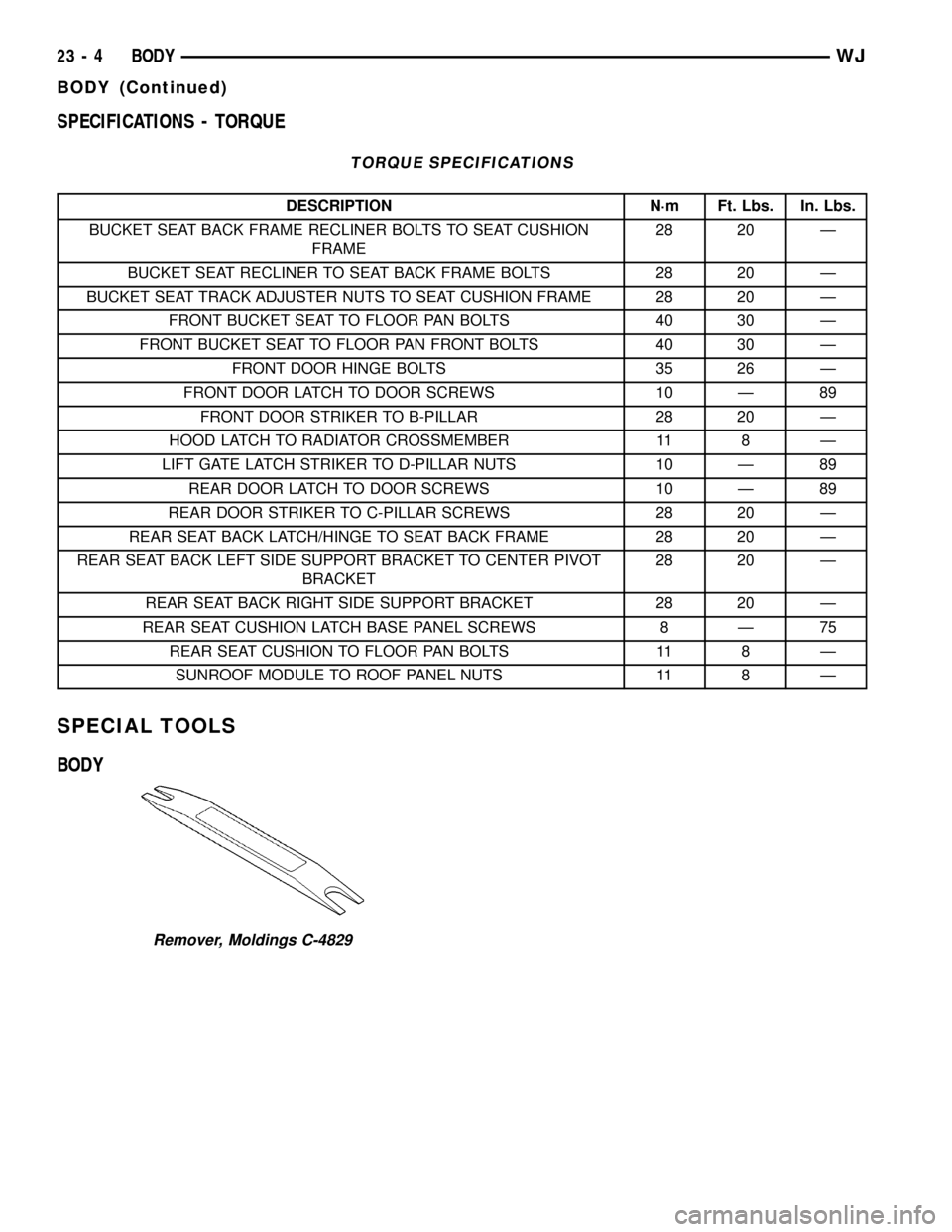
SPECIFICATIONS - TORQUE
TORQUE SPECIFICATIONS
DESCRIPTION N´m Ft. Lbs. In. Lbs.
BUCKET SEAT BACK FRAME RECLINER BOLTS TO SEAT CUSHION
FRAME28 20 Ð
BUCKET SEAT RECLINER TO SEAT BACK FRAME BOLTS 28 20 Ð
BUCKET SEAT TRACK ADJUSTER NUTS TO SEAT CUSHION FRAME 28 20 Ð
FRONT BUCKET SEAT TO FLOOR PAN BOLTS 40 30 Ð
FRONT BUCKET SEAT TO FLOOR PAN FRONT BOLTS 40 30 Ð
FRONT DOOR HINGE BOLTS 35 26 Ð
FRONT DOOR LATCH TO DOOR SCREWS 10 Ð 89
FRONT DOOR STRIKER TO B-PILLAR 28 20 Ð
HOOD LATCH TO RADIATOR CROSSMEMBER 11 8 Ð
LIFT GATE LATCH STRIKER TO D-PILLAR NUTS 10 Ð 89
REAR DOOR LATCH TO DOOR SCREWS 10 Ð 89
REAR DOOR STRIKER TO C-PILLAR SCREWS 28 20 Ð
REAR SEAT BACK LATCH/HINGE TO SEAT BACK FRAME 28 20 Ð
REAR SEAT BACK LEFT SIDE SUPPORT BRACKET TO CENTER PIVOT
BRACKET28 20 Ð
REAR SEAT BACK RIGHT SIDE SUPPORT BRACKET 28 20 Ð
REAR SEAT CUSHION LATCH BASE PANEL SCREWS 8 Ð 75
REAR SEAT CUSHION TO FLOOR PAN BOLTS 11 8 Ð
SUNROOF MODULE TO ROOF PANEL NUTS 11 8 Ð
SPECIAL TOOLS
BODY
Remover, Moldings C-4829
23 - 4 BODYWJ
BODY (Continued)
Page 1881 of 2199
LATCH
REMOVAL
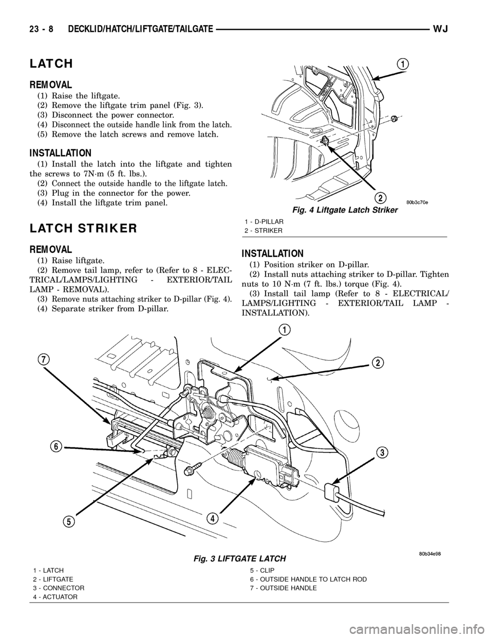
(1) Raise the liftgate.
(2) Remove the liftgate trim panel (Fig. 3).
(3) Disconnect the power connector.
(4)
Disconnect the outside handle link from the latch.
(5) Remove the latch screws and remove latch.
INSTALLATION
(1) Install the latch into the liftgate and tighten
the screws to 7N´m (5 ft. lbs.).
(2)
Connect the outside handle to the liftgate latch.
(3) Plug in the connector for the power.
(4) Install the liftgate trim panel.
LATCH STRIKER
REMOVAL
(1) Raise liftgate.
(2) Remove tail lamp, refer to (Refer to 8 - ELEC-
TRICAL/LAMPS/LIGHTING - EXTERIOR/TAIL
LAMP - REMOVAL).
(3)
Remove nuts attaching striker to D-pillar (Fig. 4).
(4) Separate striker from D-pillar.
INSTALLATION
(1) Position striker on D-pillar.
(2) Install nuts attaching striker to D-pillar. Tighten
nuts to 10 N´m (7 ft. lbs.) torque (Fig. 4).
(3) Install tail lamp (Refer to 8 - ELECTRICAL/
LAMPS/LIGHTING - EXTERIOR/TAIL LAMP -
INSTALLATION).
Fig. 3 LIFTGATE LATCH
1-LATCH
2 - LIFTGATE
3 - CONNECTOR
4 - ACTUATOR5 - CLIP
6 - OUTSIDE HANDLE TO LATCH ROD
7 - OUTSIDE HANDLE
Fig. 4 Liftgate Latch Striker
1 - D-PILLAR
2 - STRIKER
23 - 8 DECKLID/HATCH/LIFTGATE/TAILGATEWJ
Page 1888 of 2199
INSTALLATION
(1) Position hinge on ªAº pillar. (Use 3MtFast and
Firm or equivalent on the hinge to body mating sur-
face as a sealant.)
(2) Install hinge to body bolts, but do not tighten.
(3) Align the hinge to the reference marks and
torque the bolts to 35N´m (26 ft. lbs.).
(4) Install the door on the hinge and align with the
reference marks.
(5) Tighten the door to hinge fasteners.
(6) For adjustment see door adjustment procedure.
INSIDE HANDLE ACTUATOR
REMOVAL
(1) Remove door trim panel, refer to (Refer to 23 -
BODY/DOOR - FRONT/TRIM PANEL - REMOVAL).
(2) Disconnect latch and lock rods from inside han-
dle actuator.
(3) Remove screws attaching inside handle actua-
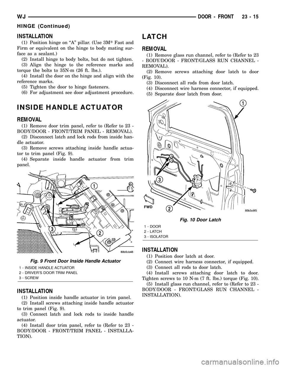
tor to trim panel (Fig. 9).
(4) Separate inside handle actuator from trim
panel.
INSTALLATION
(1) Position inside handle actuator in trim panel.
(2) Install screws attaching inside handle actuator
to trim panel (Fig. 9).
(3) Connect latch and lock rods to inside handle
actuator.
(4) Install door trim panel, refer to (Refer to 23 -
BODY/DOOR - FRONT/TRIM PANEL - INSTALLA-
TION).
LATCH
REMOVAL
(1) Remove glass run channel, refer to (Refer to 23
- BODY/DOOR - FRONT/GLASS RUN CHANNEL -
REMOVAL).
(2) Remove screws attaching door latch to door
(Fig. 10).
(3) Disconnect all rods from door latch.
(4) Disconnect wire harness connector, if equipped.
(5) Separate door latch from door.
INSTALLATION
(1) Position door latch at door.
(2) Connect wire harness connector, if equipped.
(3) Connect all rods to door latch.
(4) Install screws attaching door latch to door.
Tighten screws to 10 N´m (7 ft. lbs.) torque (Fig. 10).
(5) Install glass run channel, refer to (Refer to 23 -
BODY/DOOR - FRONT/GLASS RUN CHANNEL -
INSTALLATION).
Fig. 9 Front Door Inside Handle Actuator
1 - INSIDE HANDLE ACTUATOR
2 - DRIVER'S DOOR TRIM PANEL
3 - SCREW
Fig. 10 Door Latch
1 - DOOR
2-LATCH
3 - ISOLATOR
WJDOOR - FRONT 23 - 15
HINGE (Continued)
Page 1889 of 2199
ADJUSTMENTS
DOOR LATCH
DOOR LATCH ADJUSTMENT
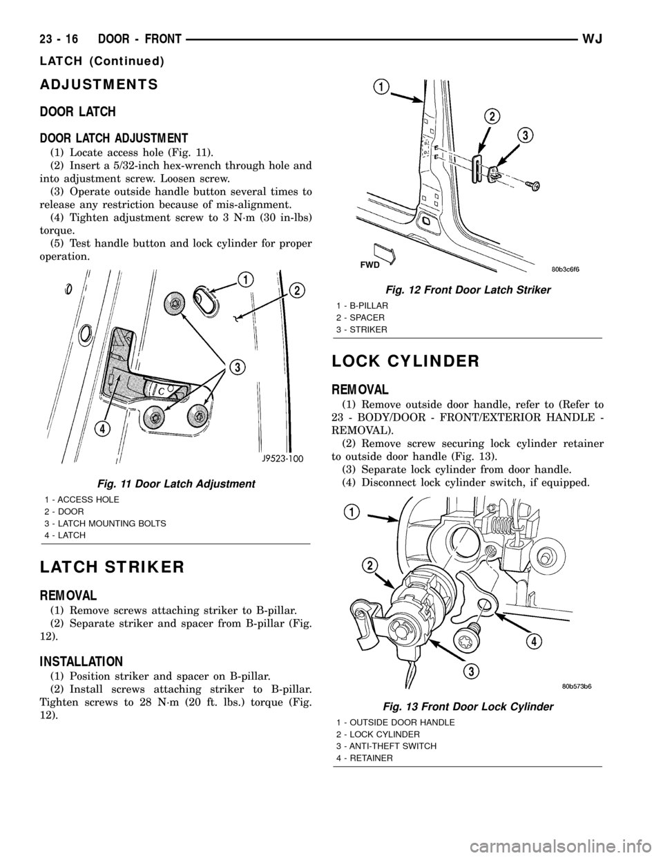
(1) Locate access hole (Fig. 11).
(2) Insert a 5/32-inch hex-wrench through hole and
into adjustment screw. Loosen screw.
(3) Operate outside handle button several times to
release any restriction because of mis-alignment.
(4) Tighten adjustment screw to 3 N´m (30 in-lbs)
torque.
(5) Test handle button and lock cylinder for proper
operation.
LATCH STRIKER
REMOVAL
(1) Remove screws attaching striker to B-pillar.
(2) Separate striker and spacer from B-pillar (Fig.
12).
INSTALLATION
(1) Position striker and spacer on B-pillar.
(2) Install screws attaching striker to B-pillar.
Tighten screws to 28 N´m (20 ft. lbs.) torque (Fig.
12).
LOCK CYLINDER
REMOVAL
(1) Remove outside door handle, refer to (Refer to
23 - BODY/DOOR - FRONT/EXTERIOR HANDLE -
REMOVAL).
(2) Remove screw securing lock cylinder retainer
to outside door handle (Fig. 13).
(3) Separate lock cylinder from door handle.
(4) Disconnect lock cylinder switch, if equipped.
Fig. 11 Door Latch Adjustment
1 - ACCESS HOLE
2 - DOOR
3 - LATCH MOUNTING BOLTS
4-LATCH
Fig. 12 Front Door Latch Striker
1 - B-PILLAR
2 - SPACER
3 - STRIKER
Fig. 13 Front Door Lock Cylinder
1 - OUTSIDE DOOR HANDLE
2 - LOCK CYLINDER
3 - ANTI-THEFT SWITCH
4 - RETAINER
23 - 16 DOOR - FRONTWJ
LATCH (Continued)
Page 1895 of 2199
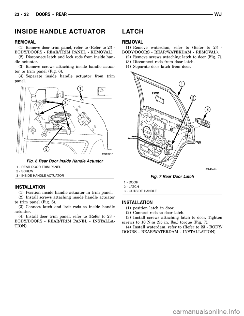
INSIDE HANDLE ACTUATOR
REMOVAL
(1) Remove door trim panel, refer to (Refer to 23 -
BODY/DOORS - REAR/TRIM PANEL - REMOVAL).
(2) Disconnect latch and lock rods from inside han-
dle actuator.
(3) Remove screws attaching inside handle actua-
tor to trim panel (Fig. 6).
(4) Separate inside handle actuator from trim
panel.
INSTALLATION
(1) Position inside handle actuator in trim panel.
(2) Install screws attaching inside handle actuator
to trim panel (Fig. 6).
(3) Connect latch and lock rods to inside handle
actuator.
(4) Install door trim panel, refer to (Refer to 23 -
BODY/DOORS - REAR/TRIM PANEL - INSTALLA-
TION).
LATCH
REMOVAL
(1) Remove waterdam, refer to (Refer to 23 -
BODY/DOORS - REAR/WATERDAM - REMOVAL).
(2) Remove screws attaching latch to door (Fig. 7).
(3) Disconnect rods from door latch.
(4) Separate door latch from door.
INSTALLATION
(1) position latch in door.
(2) Connect rods to door latch.
(3) Install screws attaching latch to door. Tighten
screws to 10 N´m (95 in. lbs.) torque (Fig. 7).
(4) Install waterdam, refer to (Refer to 23 - BODY/
DOORS - REAR/WATERDAM - INSTALLATION).
Fig. 6 Rear Door Inside Handle Actuator
1 - REAR DOOR TRIM PANEL
2 - SCREW
3 - INSIDE HANDLE ACTUATOR
Fig. 7 Rear Door Latch
1 - DOOR
2-LATCH
3 - OUTSIDE HANDLE
23 - 22 DOORS - REARWJ
Page 1896 of 2199
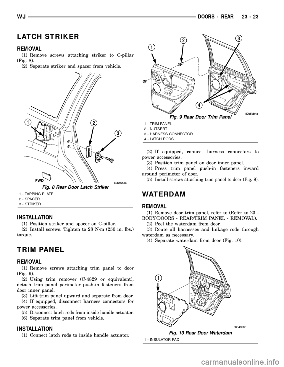
LATCH STRIKER
REMOVAL
(1) Remove screws attaching striker to C-pillar
(Fig. 8).
(2) Separate striker and spacer from vehicle.
INSTALLATION
(1) Position striker and spacer on C-pillar.
(2) Install screws. Tighten to 28 N´m (250 in. lbs.)
torque.
TRIM PANEL
REMOVAL
(1) Remove screws attaching trim panel to door
(Fig. 9).
(2) Using trim remover (C-4829 or equivalent),
detach trim panel perimeter push-in fasteners from
door inner panel.
(3) Lift trim panel upward and separate from door.
(4) If equipped, disconnect harness connectors for
power accessories.
(5)
Disconnect latch rods from inside handle actuator.
(6) Separate trim panel from vehicle.
INSTALLATION
(1) Connect latch rods to inside handle actuator.(2) If equipped, connect harness connectors to
power accessories.
(3) Position trim panel on door inner panel.
(4) Press trim panel push-in fasteners inward
around perimeter of door.
(5)
Install screws attaching trim panel to door (Fig. 9).
WATERDAM
REMOVAL
(1) Remove door trim panel, refer to (Refer to 23 -
BODY/DOORS - REAR/TRIM PANEL - REMOVAL).
(2) Peel the waterdam from door.
(3) Route all harnesses and linkage rods through
waterdam as necessary.
(4) Separate waterdam from door (Fig. 10).
Fig. 8 Rear Door Latch Striker
1 - TAPPING PLATE
2 - SPACER
3 - STRIKER
Fig. 9 Rear Door Trim Panel
1 - TRIM PANEL
2 - NUTSERT
3 - HARNESS CONNECTOR
4 - LATCH RODS
Fig. 10 Rear Door Waterdam
1 - INSULATOR PAD
WJDOORS - REAR 23 - 23
Page 1907 of 2199
(6) Remove bolts attaching hinges to hood.
(7) With the aid of a helper, remove hood from
vehicle.
INSTALLATION
(1) Position hood on hinges.
(2) Install bolts finger-tight.
(3) Align hinges with installation reference marks
and tighten bolts.
(4) Install hood support prop rods.
(5) Connect underhood lamp connector.
(6) Inspect hood for proper alignment and adjust
as necessary.
ADJUSTMENTS
HOOD ADJUSTMENT
The hood attaching holes are enlarged to aid front,
back and side to side adjustment.
(1) If hood is low in relation to cowl panel, insert
shims between hinge and hood.
(2) Adjust hood bumper in or out to adjust hood-
to-fender height alignment.
(3) Adjust the hood latch as necessary. Tighten the
nuts to 11N´m (8 ft. lbs.).
(4) Align the latch striker so that striker enters
the latch squarely and without binding.
INSULATION
REMOVAL
(1) Raise the hood.
(2) Remove the insulation panel fasteners.
(3) Remove the hood insulation panel.
INSTALLATION
(1) Position the insulation panel on the underside
of the hood.
(2) Install the insulation panel fasteners.
(3) Close the hood.
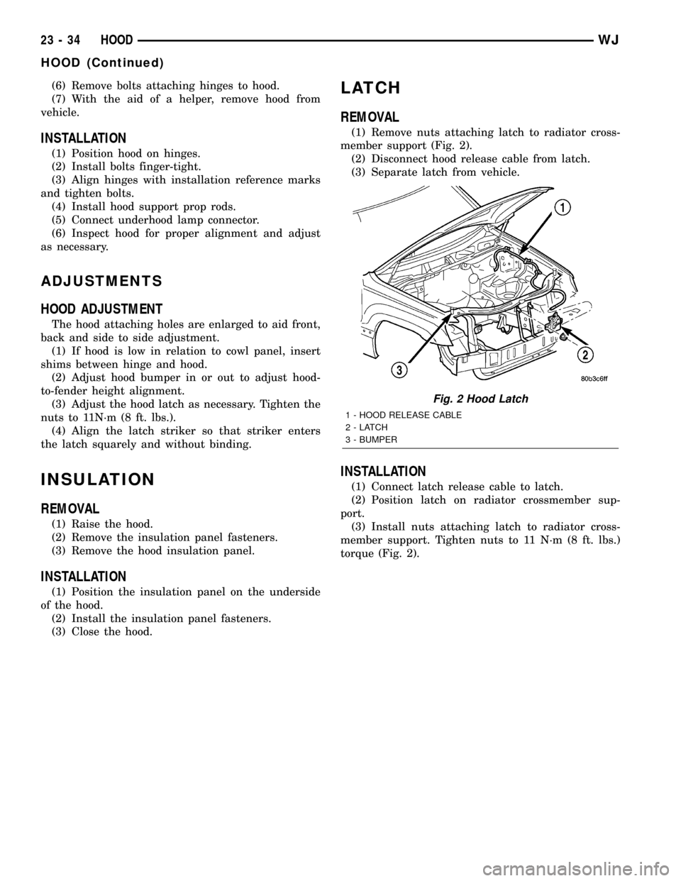
LATCH
REMOVAL
(1) Remove nuts attaching latch to radiator cross-
member support (Fig. 2).
(2) Disconnect hood release cable from latch.
(3) Separate latch from vehicle.
INSTALLATION
(1) Connect latch release cable to latch.
(2) Position latch on radiator crossmember sup-
port.
(3) Install nuts attaching latch to radiator cross-
member support. Tighten nuts to 11 N´m (8 ft. lbs.)
torque (Fig. 2).
Fig. 2 Hood Latch
1 - HOOD RELEASE CABLE
2-LATCH
3 - BUMPER
23 - 34 HOODWJ
HOOD (Continued)
Page 1953 of 2199
INSTALLATION
(1) Position the bin hooks high in the slots on the
quarter trim panel.
(2) Push downward until the bin snaps into place.
(3) Install the hinge screws.
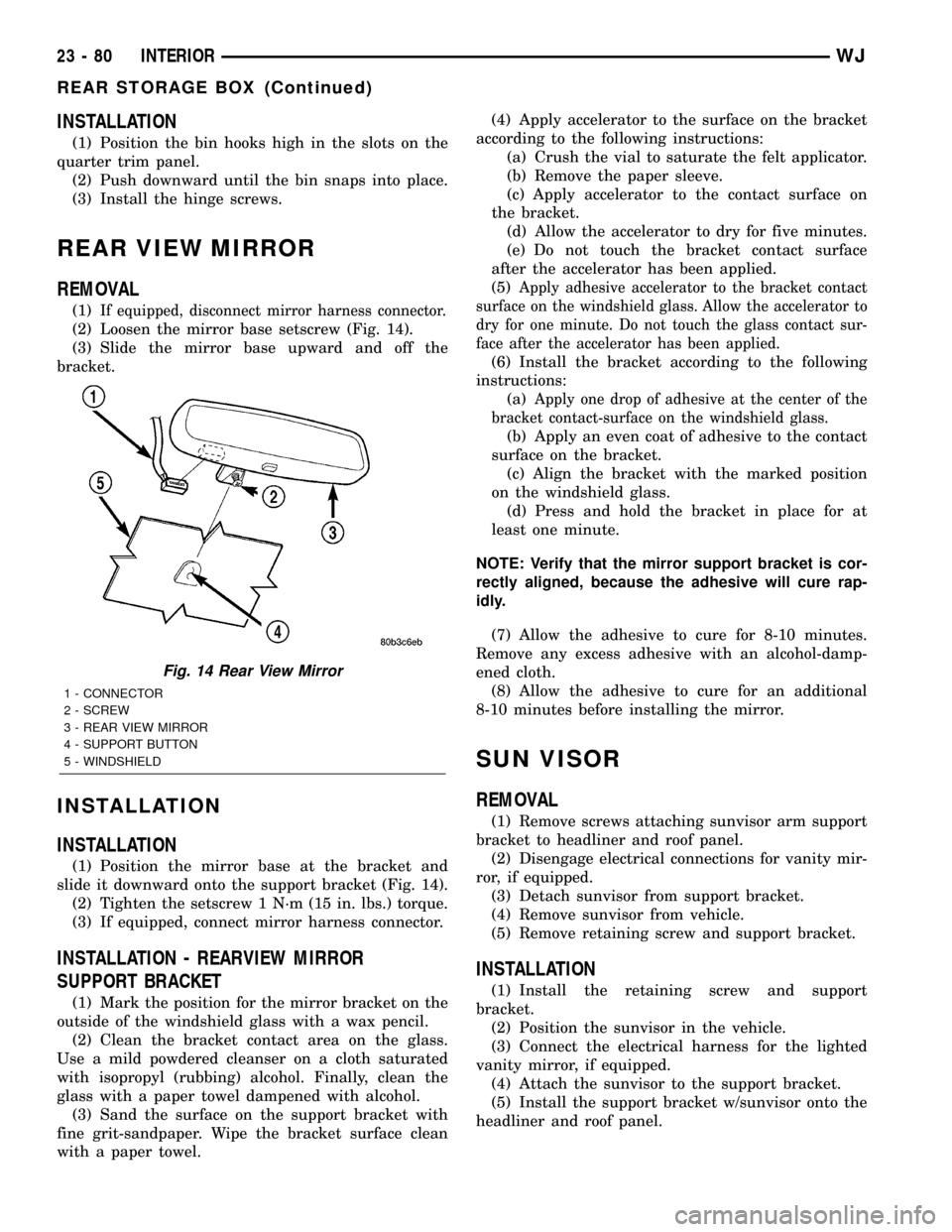
REAR VIEW MIRROR
REMOVAL
(1)If equipped, disconnect mirror harness connector.
(2) Loosen the mirror base setscrew (Fig. 14).
(3) Slide the mirror base upward and off the
bracket.
INSTALLATION
INSTALLATION
(1) Position the mirror base at the bracket and
slide it downward onto the support bracket (Fig. 14).
(2) Tighten the setscrew 1 N´m (15 in. lbs.) torque.
(3) If equipped, connect mirror harness connector.
INSTALLATION - REARVIEW MIRROR
SUPPORT BRACKET
(1) Mark the position for the mirror bracket on the
outside of the windshield glass with a wax pencil.
(2) Clean the bracket contact area on the glass.
Use a mild powdered cleanser on a cloth saturated
with isopropyl (rubbing) alcohol. Finally, clean the
glass with a paper towel dampened with alcohol.
(3) Sand the surface on the support bracket with
fine grit-sandpaper. Wipe the bracket surface clean
with a paper towel.(4) Apply accelerator to the surface on the bracket
according to the following instructions:
(a) Crush the vial to saturate the felt applicator.
(b) Remove the paper sleeve.
(c) Apply accelerator to the contact surface on
the bracket.
(d) Allow the accelerator to dry for five minutes.
(e) Do not touch the bracket contact surface
after the accelerator has been applied.
(5)
Apply adhesive accelerator to the bracket contact
surface on the windshield glass. Allow the accelerator to
dry for one minute. Do not touch the glass contact sur-
face after the accelerator has been applied.
(6) Install the bracket according to the following
instructions:
(a)
Apply one drop of adhesive at the center of the
bracket contact-surface on the windshield glass.
(b) Apply an even coat of adhesive to the contact
surface on the bracket.
(c) Align the bracket with the marked position
on the windshield glass.
(d) Press and hold the bracket in place for at
least one minute.
NOTE: Verify that the mirror support bracket is cor-
rectly aligned, because the adhesive will cure rap-
idly.
(7) Allow the adhesive to cure for 8-10 minutes.
Remove any excess adhesive with an alcohol-damp-
ened cloth.
(8) Allow the adhesive to cure for an additional
8-10 minutes before installing the mirror.
SUN VISOR
REMOVAL
(1) Remove screws attaching sunvisor arm support
bracket to headliner and roof panel.
(2) Disengage electrical connections for vanity mir-
ror, if equipped.
(3) Detach sunvisor from support bracket.
(4) Remove sunvisor from vehicle.
(5) Remove retaining screw and support bracket.
INSTALLATION
(1) Install the retaining screw and support
bracket.
(2) Position the sunvisor in the vehicle.
(3) Connect the electrical harness for the lighted
vanity mirror, if equipped.
(4) Attach the sunvisor to the support bracket.
(5) Install the support bracket w/sunvisor onto the
headliner and roof panel.
Fig. 14 Rear View Mirror
1 - CONNECTOR
2 - SCREW
3 - REAR VIEW MIRROR
4 - SUPPORT BUTTON
5 - WINDSHIELD
23 - 80 INTERIORWJ
REAR STORAGE BOX (Continued)
Page 1958 of 2199
INSTALLATION
(1) Position seat on floor pan.
(2) If equipped, connect power seat wire harness
connector.
(3) Install rear bolts attaching seat to floor pan.
Tighten bolts to 40 N´m (30 ft. lbs.) torque.
(4) If equipped, install cover on seat track.
(5) Move seat to full rearward position.
(6) Install front bolts attaching seat to floor pan.
Tighten bolts to 40 N´m (30 ft. lbs.) torque.
FRONT SEAT BACK
REMOVAL
(1) Move seat to full rearward position.
(2) Remove inboard bolt attaching seat back frame
to seat cushion frame.
(3) Move seat to full forward position.
(4) Move seat back to full recline position.
(5) Remove screws attaching seat side shield to
seat frame.
(6) Disconnect wire harness connector from
recliner motor, if equipped.
(7) From the underside of the seat, disconnect the
wire harness connector for the power lumber and/or
heated seat, if equipped.
(8) Remove outboard bolts attaching recliner to
seat cushion frame.
(9) Route the power lumber and/or heated seat
harness through the seat cushion cover, if equipped.
(10) Separate seat back from seat cushion.
INSTALLATION
(1) Position seat back on seat cushion.
(2) Route the power lumber and heater harness
through the seat cushion cover, if equipped.
(3) Install recliner bolts attaching seat back frame
to seat cushion frame. Tighten bolts to 28 N´m (20 ft.
lbs.) torque.
(4) Install the inboard bolt attaching seat back
frame to seat cushion frame. Tighten bolt to 47N´m
(35 ft.lbs.).
(5) Connect wire harness connector to recliner
motor and/or heated seat, if equipped.
(6) From the underside of the seat, connect the
power lumber and/or heated seat wire harness con-
nector to the seat harness, if equipped.
(7) Install screws attaching seat side shield to seat
frame.
FRONT SEAT BACK COVER
REMOVAL
(1) Remove head restraint (Refer to 23 - BODY/
SEATS/FRONT HEADREST - REMOVAL).
(2) Using a trim stick, carefully pry head restraint
release button caps from the top of seat back.
(3) Remove seat back (Refer to 23 - BODY/SEATS/
FRONT SEAT BACK - REMOVAL).
(4) Disengage J-strap at base of seat back.
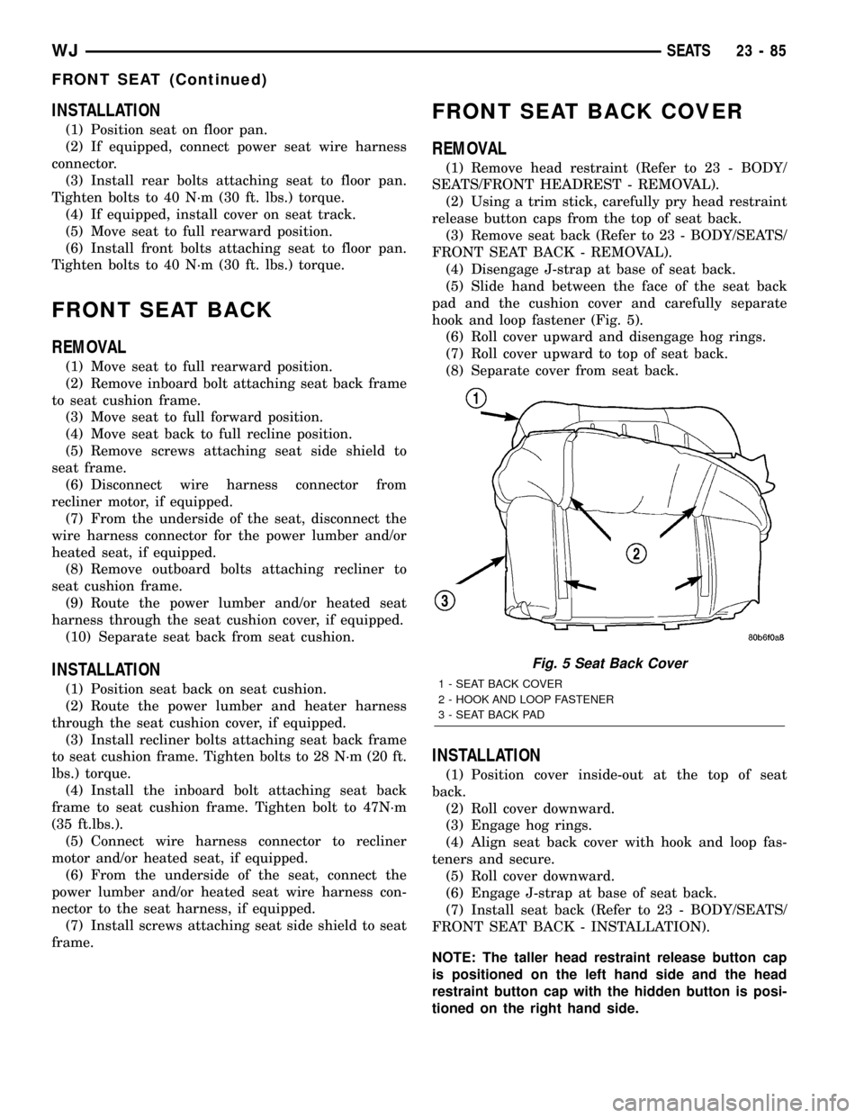
(5) Slide hand between the face of the seat back
pad and the cushion cover and carefully separate
hook and loop fastener (Fig. 5).
(6) Roll cover upward and disengage hog rings.
(7) Roll cover upward to top of seat back.
(8) Separate cover from seat back.
INSTALLATION
(1) Position cover inside-out at the top of seat
back.
(2) Roll cover downward.
(3) Engage hog rings.
(4) Align seat back cover with hook and loop fas-
teners and secure.
(5) Roll cover downward.
(6) Engage J-strap at base of seat back.
(7) Install seat back (Refer to 23 - BODY/SEATS/
FRONT SEAT BACK - INSTALLATION).
NOTE: The taller head restraint release button cap
is positioned on the left hand side and the head
restraint button cap with the hidden button is posi-
tioned on the right hand side.
Fig. 5 Seat Back Cover
1 - SEAT BACK COVER
2 - HOOK AND LOOP FASTENER
3 - SEAT BACK PAD
WJSEATS 23 - 85
FRONT SEAT (Continued)
Page 1959 of 2199
(8) Position head restraint release button caps on
head restraint sleeves and press to secure.
(9) Install head restraint (Refer to 23 - BODY/
SEATS/FRONT HEADREST - INSTALLATION).
FRONT SEAT CUSHION/COVER
REMOVAL
(1) Remove seat from vehicle (Refer to 23 - BODY/
SEATS/FRONT SEAT - REMOVAL).
(2) Remove seat back (Refer to 23 - BODY/SEATS/
FRONT SEAT BACK - REMOVAL).
(3) Disengage J-straps attaching cushion cover to
seat cushion frame.
(4) Disengage hog rings attaching cushion cover to
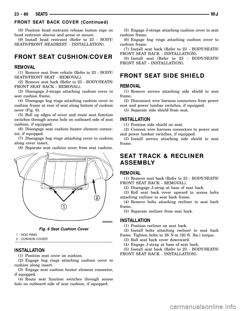
cushion frame at rear of seat along bottom of cushion
cover (Fig. 6).
(5) Roll up edges of cover and route seat function
switches through access hole on outboard side of seat
cushion, if equipped.
(6) Disengage seat cushion heater element connec-
tor, if equipped.
(7) Disengage hog rings attaching cover to cushion
along cover insert.
(8) Separate seat cushion cover from seat cushion.
INSTALLATION
(1) Position seat cover on cushion.
(2) Engage hog rings attaching cushion cover to
cushion along insert.
(3) Engage seat cushion heater element connector,
if equipped.
(4) Route seat function switches through access
hole on outboard side of seat cushion, if equipped.(5) Engage J-straps attaching cushion cover to seat
cushion frame.
(6) Engage hog rings attaching cushion cover to
cushion frame.
(7) Install seat back (Refer to 23 - BODY/SEATS/
FRONT SEAT BACK - INSTALLATION).
(8) Install seat (Refer to 23 - BODY/SEATS/
FRONT SEAT - INSTALLATION).
FRONT SEAT SIDE SHIELD
REMOVAL
(1) Remove screws attaching side shield to seat
frame.
(2) Disconnect wire harness connectors from power
seat and power lumbar switches, if equipped.
(3) Separate side shield from seat.
INSTALLATION
(1) Position side shield on seat.
(2) Connect wire harness connectors to power seat
and power lumbar switches, if equipped.
(3) Install screws attaching side shield to seat
frame.
SEAT TRACK & RECLINER
ASSEMBLY
REMOVAL
(1) Remove seat back (Refer to 23 - BODY/SEATS/
FRONT SEAT BACK - REMOVAL).
(2) Disengage J-strap at base of seat back.
(3) Roll seat back cover upward to access bolts
attaching recliner to seat back frame.
(4) Remove bolts attaching recliner to seat back
frame.
(5) Separate recliner from seat back.
INSTALLATION
(1) Position recliner on seat back.
(2) Install bolts attaching recliner to seat back
frame. Tighten bolts to 28 N´m (20 ft. lbs.) torque.
(3) Roll seat back cover downward.
(4) Engage J-strap at base of seat back.
(5) Install seat back (Refer to 23 - BODY/SEATS/
FRONT SEAT BACK - INSTALLATION).Fig. 6 Seat Cushion Cover
1 - HOG RING
2 - CUSHION COVER
23 - 86 SEATSWJ
FRONT SEAT BACK COVER (Continued)