Auto shut down relay JEEP GRAND CHEROKEE 2002 WJ / 2.G Owner's Guide
[x] Cancel search | Manufacturer: JEEP, Model Year: 2002, Model line: GRAND CHEROKEE, Model: JEEP GRAND CHEROKEE 2002 WJ / 2.GPages: 2199, PDF Size: 76.01 MB
Page 1133 of 2199
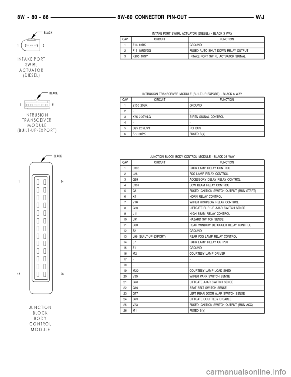
INTAKE PORT SWIRL ACTUATOR (DIESEL) - BLACK 3 WAY
CAV CIRCUIT FUNCTION
1 Z18 18BK GROUND
2 F15 18RD/DG FUSED AUTO SHUT DOWN RELAY OUTPUT
3 K900 18GY INTAKE PORT SWIRL ACTUATOR SIGNAL
INTRUSION TRANSCEIVER MODULE (BUILT-UP-EXPORT) - BLACK 6 WAY
CAV CIRCUIT FUNCTION
1 Z155 20BK GROUND
2- -
3 X75 20GY/LG SIREN SIGNAL CONTROL
4- -
5 D25 20YL/VT PCI BUS
6 F70 20PK FUSED B(+)
JUNCTION BLOCK BODY CONTROL MODULE - BLACK 26 WAY
CAV CIRCUIT FUNCTION
1 L308 PARK LAMP RELAY CONTROL
2 L26 FOG LAMP RELAY CONTROL
3 Q29 ACCESSORY DELAY RELAY CONTROL
4 L307 LOW BEAM RELAY CONTROL
5 G5 FUSED IGNITION SWITCH OUTPUT (RUN-START)
6 X4 HORN RELAY CONTROL
7 V16 WIPER HIGH/LOW RELAY CONTROL
8 G80 LIFTGATE FLIP-UP AJAR SWITCH SENSE
9 L11 HIGH BEAM RELAY CONTROL
10 L91 HAZARD SWITCH SENSE
11 C80 REAR WINDOW DEFOGGER RELAY CONTROL
12 Z2 GROUND
13 L96 (BUILT-UP-EXPORT) REAR FOG LAMP RELAY CONTROL
14 L7 PARK LAMP RELAY OUTPUT
15 Z1 GROUND
16 M2 COURTESY LAMP DRIVER
17 - -
18 - -
19 M20 COURTESY LAMP LOAD SHED
20 V55 WIPER PARK SWITCH SENSE
21 G78 LIFTGATE AJAR SWITCH SENSE
22 G10 SEAT BELT SWITCH SENSE
23 G77 LEFT REAR DOOR AJAR SWITCH SENSE
24 G73 LIFTGATE COURTESY DISABLE
25 V23 FUSED IGNITION SWITCH OUTPUT (RUN-ACC)
26 M1 FUSED B(+)
8W - 80 - 86 8W-80 CONNECTOR PIN-OUTWJ
Page 1146 of 2199
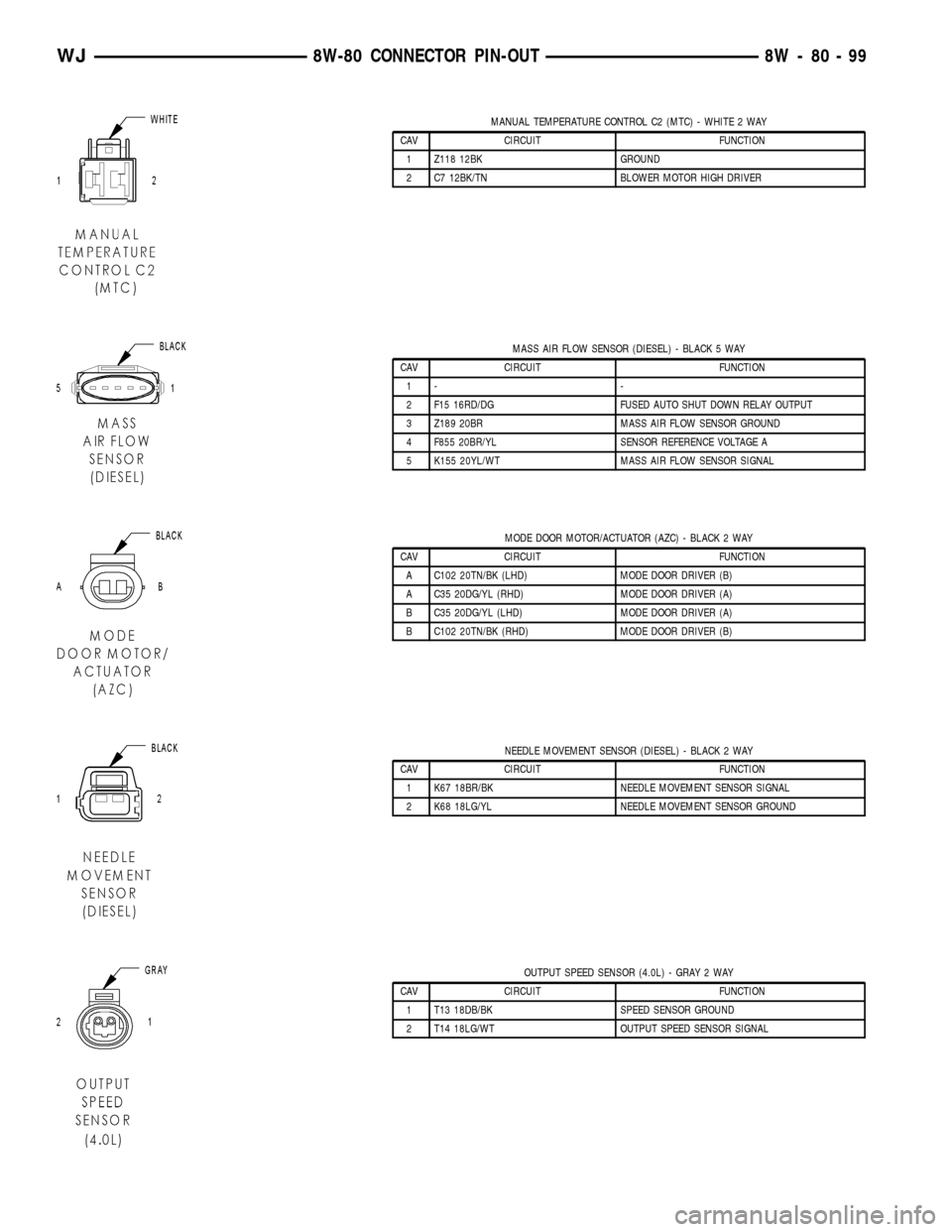
MANUAL TEMPERATURE CONTROL C2 (MTC) - WHITE 2 WAY
CAV CIRCUIT FUNCTION
1 Z118 12BK GROUND
2 C7 12BK/TN BLOWER MOTOR HIGH DRIVER
MASS AIR FLOW SENSOR (DIESEL) - BLACK 5 WAY
CAV CIRCUIT FUNCTION
1- -
2 F15 16RD/DG FUSED AUTO SHUT DOWN RELAY OUTPUT
3 Z189 20BR MASS AIR FLOW SENSOR GROUND
4 F855 20BR/YL SENSOR REFERENCE VOLTAGE A
5 K155 20YL/WT MASS AIR FLOW SENSOR SIGNAL
MODE DOOR MOTOR/ACTUATOR (AZC) - BLACK 2 WAY
CAV CIRCUIT FUNCTION
A C102 20TN/BK (LHD) MODE DOOR DRIVER (B)
A C35 20DG/YL (RHD) MODE DOOR DRIVER (A)
B C35 20DG/YL (LHD) MODE DOOR DRIVER (A)
B C102 20TN/BK (RHD) MODE DOOR DRIVER (B)
NEEDLE MOVEMENT SENSOR (DIESEL) - BLACK 2 WAY
CAV CIRCUIT FUNCTION
1 K67 18BR/BK NEEDLE MOVEMENT SENSOR SIGNAL
2 K68 18LG/YL NEEDLE MOVEMENT SENSOR GROUND
OUTPUT SPEED SENSOR (4.0L) - GRAY 2 WAY
CAV CIRCUIT FUNCTION
1 T13 18DB/BK SPEED SENSOR GROUND
2 T14 18LG/WT OUTPUT SPEED SENSOR SIGNAL
WJ8W-80 CONNECTOR PIN-OUT 8W - 80 - 99
Page 1147 of 2199
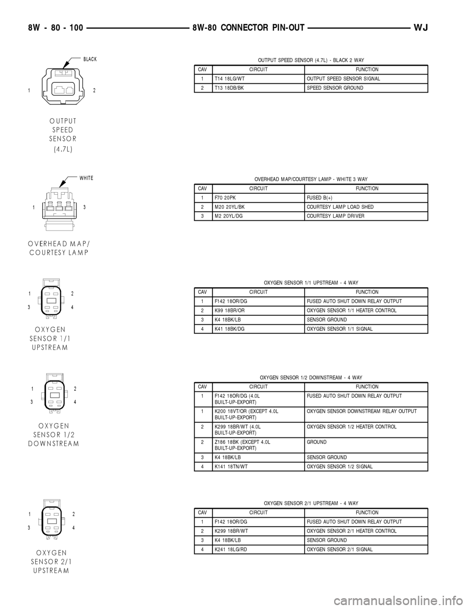
OUTPUT SPEED SENSOR (4.7L) - BLACK 2 WAY
CAV CIRCUIT FUNCTION
1 T14 18LG/WT OUTPUT SPEED SENSOR SIGNAL
2 T13 18DB/BK SPEED SENSOR GROUND
OVERHEAD MAP/COURTESY LAMP - WHITE 3 WAY
CAV CIRCUIT FUNCTION
1 F70 20PK FUSED B(+)
2 M20 20YL/BK COURTESY LAMP LOAD SHED
3 M2 20YL/DG COURTESY LAMP DRIVER
OXYGEN SENSOR 1/1 UPSTREAM-4WAY
CAV CIRCUIT FUNCTION
1 F142 18OR/DG FUSED AUTO SHUT DOWN RELAY OUTPUT
2 K99 18BR/OR OXYGEN SENSOR 1/1 HEATER CONTROL
3 K4 18BK/LB SENSOR GROUND
4 K41 18BK/DG OXYGEN SENSOR 1/1 SIGNAL
OXYGEN SENSOR 1/2 DOWNSTREAM-4WAY
CAV CIRCUIT FUNCTION
1 F142 18OR/DG (4.0L
BUILT-UP-EXPORT)FUSED AUTO SHUT DOWN RELAY OUTPUT
1 K200 18VT/OR (EXCEPT 4.0L
BUILT-UP-EXPORT)OXYGEN SENSOR DOWNSTREAM RELAY OUTPUT
2 K299 18BR/WT (4.0L
BUILT-UP-EXPORT)OXYGEN SENSOR 1/2 HEATER CONTROL
2 Z186 18BK (EXCEPT 4.0L
BUILT-UP-EXPORT)GROUND
3 K4 18BK/LB SENSOR GROUND
4 K141 18TN/WT OXYGEN SENSOR 1/2 SIGNAL
OXYGEN SENSOR 2/1 UPSTREAM-4WAY
CAV CIRCUIT FUNCTION
1 F142 18OR/DG FUSED AUTO SHUT DOWN RELAY OUTPUT
2 K299 18BR/WT OXYGEN SENSOR 2/1 HEATER CONTROL
3 K4 18BK/LB SENSOR GROUND
4 K241 18LG/RD OXYGEN SENSOR 2/1 SIGNAL
8W - 80 - 100 8W-80 CONNECTOR PIN-OUTWJ
Page 1157 of 2199
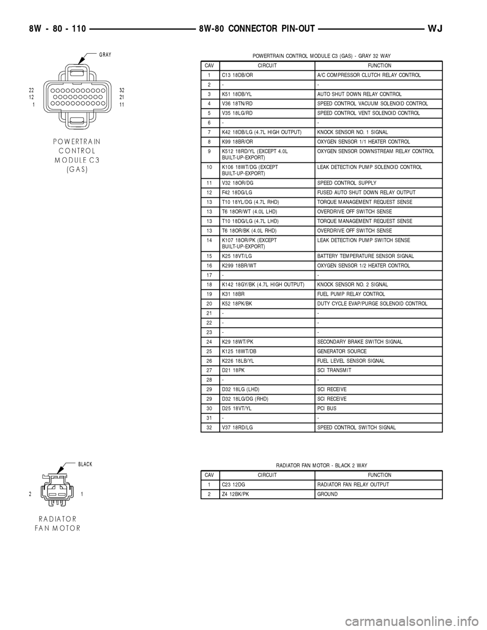
POWERTRAIN CONTROL MODULE C3 (GAS) - GRAY 32 WAY
CAV CIRCUIT FUNCTION
1 C13 18DB/OR A/C COMPRESSOR CLUTCH RELAY CONTROL
2- -
3 K51 18DB/YL AUTO SHUT DOWN RELAY CONTROL
4 V36 18TN/RD SPEED CONTROL VACUUM SOLENOID CONTROL
5 V35 18LG/RD SPEED CONTROL VENT SOLENOID CONTROL
6- -
7 K42 18DB/LG (4.7L HIGH OUTPUT) KNOCK SENSOR NO. 1 SIGNAL
8 K99 18BR/OR OXYGEN SENSOR 1/1 HEATER CONTROL
9 K512 18RD/YL (EXCEPT 4.0L
BUILT-UP-EXPORT)OXYGEN SENSOR DOWNSTREAM RELAY CONTROL
10 K106 18WT/DG (EXCEPT
BUILT-UP-EXPORT)LEAK DETECTION PUMP SOLENOID CONTROL
11 V32 18OR/DG SPEED CONTROL SUPPLY
12 F42 18DG/LG FUSED AUTO SHUT DOWN RELAY OUTPUT
13 T10 18YL/DG (4.7L RHD) TORQUE MANAGEMENT REQUEST SENSE
13 T6 18OR/WT (4.0L LHD) OVERDRIVE OFF SWITCH SENSE
13 T10 18DG/LG (4.7L LHD) TORQUE MANAGEMENT REQUEST SENSE
13 T6 18OR/BK (4.0L RHD) OVERDRIVE OFF SWITCH SENSE
14 K107 18OR/PK (EXCEPT
BUILT-UP-EXPORT)LEAK DETECTION PUMP SWITCH SENSE
15 K25 18VT/LG BATTERY TEMPERATURE SENSOR SIGNAL
16 K299 18BR/WT OXYGEN SENSOR 1/2 HEATER CONTROL
17 - -
18 K142 18GY/BK (4.7L HIGH OUTPUT) KNOCK SENSOR NO. 2 SIGNAL
19 K31 18BR FUEL PUMP RELAY CONTROL
20 K52 18PK/BK DUTY CYCLE EVAP/PURGE SOLENOID CONTROL
21 - -
22 - -
23 - -
24 K29 18WT/PK SECONDARY BRAKE SWITCH SIGNAL
25 K125 18WT/DB GENERATOR SOURCE
26 K226 18LB/YL FUEL LEVEL SENSOR SIGNAL
27 D21 18PK SCI TRANSMIT
28 - -
29 D32 18LG (LHD) SCI RECEIVE
29 D32 18LG/DG (RHD) SCI RECEIVE
30 D25 18VT/YL PCI BUS
31 - -
32 V37 18RD/LG SPEED CONTROL SWITCH SIGNAL
RADIATOR FAN MOTOR - BLACK 2 WAY
CAV CIRCUIT FUNCTION
1 C23 12DG RADIATOR FAN RELAY OUTPUT
2 Z4 12BK/PK GROUND
8W - 80 - 110 8W-80 CONNECTOR PIN-OUTWJ
Page 1174 of 2199
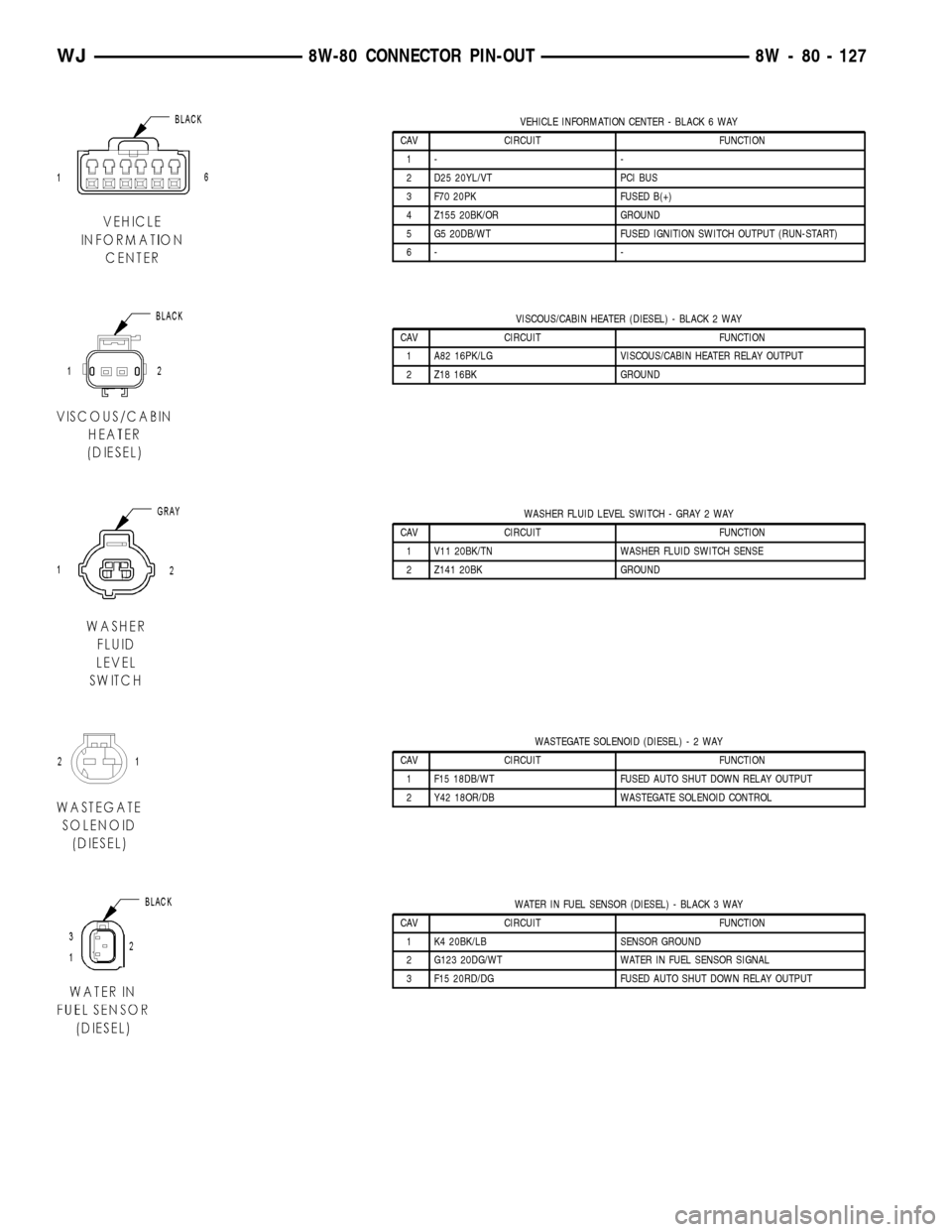
VEHICLE INFORMATION CENTER - BLACK 6 WAY
CAV CIRCUIT FUNCTION
1- -
2 D25 20YL/VT PCI BUS
3 F70 20PK FUSED B(+)
4 Z155 20BK/OR GROUND
5 G5 20DB/WT FUSED IGNITION SWITCH OUTPUT (RUN-START)
6- -
VISCOUS/CABIN HEATER (DIESEL) - BLACK 2 WAY
CAV CIRCUIT FUNCTION
1 A82 16PK/LG VISCOUS/CABIN HEATER RELAY OUTPUT
2 Z18 16BK GROUND
WASHER FLUID LEVEL SWITCH - GRAY 2 WAY
CAV CIRCUIT FUNCTION
1 V11 20BK/TN WASHER FLUID SWITCH SENSE
2 Z141 20BK GROUND
WASTEGATE SOLENOID (DIESEL)-2WAY
CAV CIRCUIT FUNCTION
1 F15 18DB/WT FUSED AUTO SHUT DOWN RELAY OUTPUT
2 Y42 18OR/DB WASTEGATE SOLENOID CONTROL
WATER IN FUEL SENSOR (DIESEL) - BLACK 3 WAY
CAV CIRCUIT FUNCTION
1 K4 20BK/LB SENSOR GROUND
2 G123 20DG/WT WATER IN FUEL SENSOR SIGNAL
3 F15 20RD/DG FUSED AUTO SHUT DOWN RELAY OUTPUT
WJ8W-80 CONNECTOR PIN-OUT 8W - 80 - 127
Page 1311 of 2199
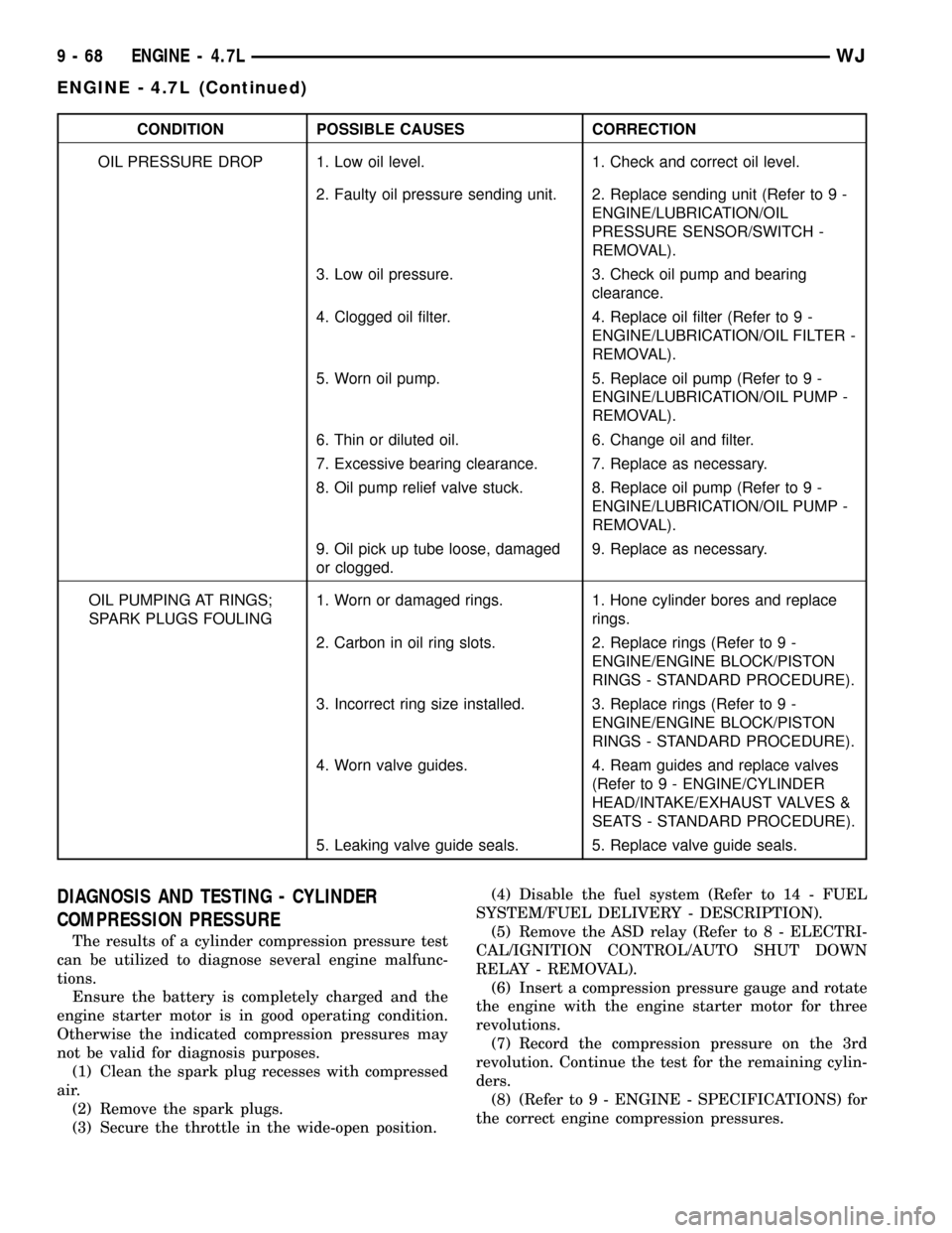
CONDITION POSSIBLE CAUSES CORRECTION
OIL PRESSURE DROP 1. Low oil level. 1. Check and correct oil level.
2. Faulty oil pressure sending unit. 2. Replace sending unit (Refer to 9 -
ENGINE/LUBRICATION/OIL
PRESSURE SENSOR/SWITCH -
REMOVAL).
3. Low oil pressure. 3. Check oil pump and bearing
clearance.
4. Clogged oil filter. 4. Replace oil filter (Refer to 9 -
ENGINE/LUBRICATION/OIL FILTER -
REMOVAL).
5. Worn oil pump. 5. Replace oil pump (Refer to 9 -
ENGINE/LUBRICATION/OIL PUMP -
REMOVAL).
6. Thin or diluted oil. 6. Change oil and filter.
7. Excessive bearing clearance. 7. Replace as necessary.
8. Oil pump relief valve stuck. 8. Replace oil pump (Refer to 9 -
ENGINE/LUBRICATION/OIL PUMP -
REMOVAL).
9. Oil pick up tube loose, damaged
or clogged.9. Replace as necessary.
OIL PUMPING AT RINGS;
SPARK PLUGS FOULING1. Worn or damaged rings. 1. Hone cylinder bores and replace
rings.
2. Carbon in oil ring slots. 2. Replace rings (Refer to 9 -
ENGINE/ENGINE BLOCK/PISTON
RINGS - STANDARD PROCEDURE).
3. Incorrect ring size installed. 3. Replace rings (Refer to 9 -
ENGINE/ENGINE BLOCK/PISTON
RINGS - STANDARD PROCEDURE).
4. Worn valve guides. 4. Ream guides and replace valves
(Refer to 9 - ENGINE/CYLINDER
HEAD/INTAKE/EXHAUST VALVES &
SEATS - STANDARD PROCEDURE).
5. Leaking valve guide seals. 5. Replace valve guide seals.
DIAGNOSIS AND TESTING - CYLINDER
COMPRESSION PRESSURE
The results of a cylinder compression pressure test
can be utilized to diagnose several engine malfunc-
tions.
Ensure the battery is completely charged and the
engine starter motor is in good operating condition.
Otherwise the indicated compression pressures may
not be valid for diagnosis purposes.
(1) Clean the spark plug recesses with compressed
air.
(2) Remove the spark plugs.
(3) Secure the throttle in the wide-open position.(4) Disable the fuel system (Refer to 14 - FUEL
SYSTEM/FUEL DELIVERY - DESCRIPTION).
(5) Remove the ASD relay (Refer to 8 - ELECTRI-
CAL/IGNITION CONTROL/AUTO SHUT DOWN
RELAY - REMOVAL).
(6) Insert a compression pressure gauge and rotate
the engine with the engine starter motor for three
revolutions.
(7) Record the compression pressure on the 3rd
revolution. Continue the test for the remaining cylin-
ders.
(8) (Refer to 9 - ENGINE - SPECIFICATIONS) for
the correct engine compression pressures.
9 - 68 ENGINE - 4.7LWJ
ENGINE - 4.7L (Continued)
Page 1672 of 2199

MANUAL VALVE
The manual valve (Fig. 276) is a relay valve. The
purpose of the manual valve is to direct fluid to the
correct circuit needed for a specific gear or driving
range. The manual valve, as the name implies, is
manually operated by the driver with a lever located
on the side of the valve body. The valve is connected
mechanically by either a cable or linkage to the gear-
shift mechanism. The valve is held in each of its
positions by a spring-loaded roller or ball that
engages the ªroostercombº of the manual valve lever.
CONVERTER CLUTCH LOCK-UP VALVE
The torque converter clutch (TCC) lock-up valve
controls the back (ON) side of the torque converter
clutch. When the PCM energizes the TCC solenoid to
engage the converter clutch piston, pressure is
applied to the TCC lock-up valve which moves to the
right and applies pressure to the torque converter
clutch.
CONVERTER CLUTCH LOCK-UP TIMING VALVE
The torque converter clutch (TCC) lock-up timing
valve is there to block any 4-3 downshift until the
TCC is completely unlocked and the clutch is disen-
gaged.
SHUTTLE VALVE
The assembly is contained in a bore in the valve
body above the shift valves. When the manual valve
is positioned in the Drive range, throttle pressure
acts on the throttle plug of the shuttle valve (Fig.
268) to move it against a spring, increasing the
spring force on the shuttle valve. During a part or
full throttle 1-2 upshift, the throttle plug is bottomed
by throttle pressure, holding the shuttle valve to the
right against governor pressure, and opening a
by±pass circuit. The shuttle valve controls the qual-
ity of the kickdown shift by restricting the rate of
fluid discharge from the front clutch and servo
release circuits. During a 3-2 kickdown, fluid dis-
charges through the shuttle by-pass circuit. When
the shuttle valve closes the by-pass circuit, fluid dis-
charge is restricted and controlled for the application
of the front band. During a 2-3 ªlift footº upshift, the
shuttle valve by-passes the restriction to allow full
fluid flow through the by-pass groove for a faster
release of the band.
Fig. 276 Manual Valve
WJAUTOMATIC TRANSMISSION - 42RE 21 - 153
VALVE BODY (Continued)
Page 2167 of 2199
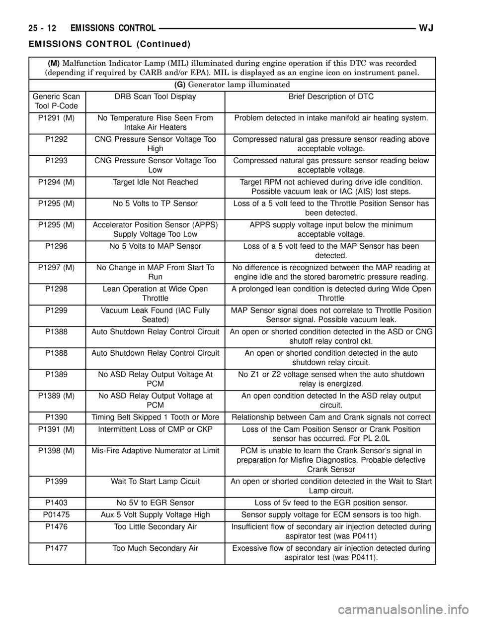
(M)Malfunction Indicator Lamp (MIL) illuminated during engine operation if this DTC was recorded
(depending if required by CARB and/or EPA). MIL is displayed as an engine icon on instrument panel.
(G)Generator lamp illuminated
Generic Scan
Tool P-CodeDRB Scan Tool Display Brief Description of DTC
P1291 (M) No Temperature Rise Seen From
Intake Air HeatersProblem detected in intake manifold air heating system.
P1292 CNG Pressure Sensor Voltage Too
HighCompressed natural gas pressure sensor reading above
acceptable voltage.
P1293 CNG Pressure Sensor Voltage Too
LowCompressed natural gas pressure sensor reading below
acceptable voltage.
P1294 (M) Target Idle Not Reached Target RPM not achieved during drive idle condition.
Possible vacuum leak or IAC (AIS) lost steps.
P1295 (M) No 5 Volts to TP Sensor Loss of a 5 volt feed to the Throttle Position Sensor has
been detected.
P1295 (M) Accelerator Position Sensor (APPS)
Supply Voltage Too LowAPPS supply voltage input below the minimum
acceptable voltage.
P1296 No 5 Volts to MAP Sensor Loss of a 5 volt feed to the MAP Sensor has been
detected.
P1297 (M) No Change in MAP From Start To
RunNo difference is recognized between the MAP reading at
engine idle and the stored barometric pressure reading.
P1298 Lean Operation at Wide Open
ThrottleA prolonged lean condition is detected during Wide Open
Throttle
P1299 Vacuum Leak Found (IAC Fully
Seated)MAP Sensor signal does not correlate to Throttle Position
Sensor signal. Possible vacuum leak.
P1388 Auto Shutdown Relay Control Circuit An open or shorted condition detected in the ASD or CNG
shutoff relay control ckt.
P1388 Auto Shutdown Relay Control Circuit An open or shorted condition detected in the auto
shutdown relay circuit.
P1389 No ASD Relay Output Voltage At
PCMNo Z1 or Z2 voltage sensed when the auto shutdown
relay is energized.
P1389 (M) No ASD Relay Output Voltage at
PCMAn open condition detected In the ASD relay output
circuit.
P1390 Timing Belt Skipped 1 Tooth or More Relationship between Cam and Crank signals not correct
P1391 (M) Intermittent Loss of CMP or CKP Loss of the Cam Position Sensor or Crank Position
sensor has occurred. For PL 2.0L
P1398 (M) Mis-Fire Adaptive Numerator at Limit PCM is unable to learn the Crank Sensor's signal in
preparation for Misfire Diagnostics. Probable defective
Crank Sensor
P1399 Wait To Start Lamp Cicuit An open or shorted condition detected in the Wait to Start
Lamp circuit.
P1403 No 5V to EGR Sensor Loss of 5v feed to the EGR position sensor.
P01475 Aux 5 Volt Supply Voltage High Sensor supply voltage for ECM sensors is too high.
P1476 Too Little Secondary Air Insufficient flow of secondary air injection detected during
aspirator test (was P0411)
P1477 Too Much Secondary Air Excessive flow of secondary air injection detected during
aspirator test (was P0411).
25 - 12 EMISSIONS CONTROLWJ
EMISSIONS CONTROL (Continued)