Console JEEP GRAND CHEROKEE 2002 WJ / 2.G Owner's Guide
[x] Cancel search | Manufacturer: JEEP, Model Year: 2002, Model line: GRAND CHEROKEE, Model: JEEP GRAND CHEROKEE 2002 WJ / 2.GPages: 2199, PDF Size: 76.01 MB
Page 611 of 2199

operates the front wipers at the programmed speed
and intervals requested by the RSM to maintain vis-
ibility through the windshield.
²Continuous Wipe Mode- The control knob on
the control stalk of the right (wiper) multi-function
switch has two continuous wipe positions, Low and
High. When selected, these switch positions will
cause the two-speed front wiper motor to operate in a
continuous low or high speed cycle.
²Headlamps On With Wipers- The BCM pro-
vides an automatic headlamps on with wipers feature
for models equipped with the optional automatic
headlamps. This is a customer programmable fea-
ture. If this feature is enabled, the headlamps will
turn on automatically when the windshield wipers
are turned on; and, if the headlamps were turned on
automatically when the wipers were turned on, they
will turn off automatically when the wipers are
turned off. In models equipped with the optional
automatic wiper feature, when the automatic wiper
mode is selected the headlamps will turn on auto-
matically only after the wipers complete three auto-
matic wipe cycles within about thirty seconds, and
they will turn off automatically after three minutes
elapse without any automatic wipe cycles. (Refer to 8
- ELECTRICAL/OVERHEAD CONSOLE - STAN-
DARD PROCEDURE - ELECTRONIC VEHICLE
INFORMATION CENTER PROGRAMMING).
²Mist Wipe Mode- The control stalk of the right
(wiper) multi-function switch has a momentary Mist
position. When selected, this switch position will
operate the front wipers in a low speed continuous
cycle for as long as the switch is held closed, then
will complete the current wipe cycle and park the
front wiper blades near the base of the windshield
when the switch is released.
²Speed Sensitive Intermittent Wipe Mode-
Except on models equipped with the optional auto-
matic wiper system, the internal circuitry of both the
right (wiper) multi-function switch and the BCM
work in concert to provide an intermittent wipe mode
with five delay interval selections. The BCM auto-
matically adjusts each manually selected delay inter-
val to compensate for vehicle speed.
²Washer Mode- When the momentary front
wash position of the control stalk for the right
(wiper) multi-function switch is selected with the
front wiper system operating in a continuous wipe
mode, washer fluid will be dispensed onto the wind-
shield glass through the washer nozzles for as long
as the washer switch is held closed. When the front
washer switch is actuated with the front wiper sys-
tem operating in an intermittent wipe mode, washer
fluid is still dispensed until the switch is released;
however, the front wipers will operate in a low speed
continuous cycle from the time the washer switch isclosed until several wipe cycles after the switch is
released, before returning to the selected intermit-
tent wipe mode.
²Wipe-After-Wash Mode- When the momentary
front wash position of the control stalk for the right
(wiper) multi-function switch is selected with the
front wiper system turned Off, the internal circuitry
of the BCM provides a wipe-after-wash feature.
When selected, this feature will operate the front
washer pump/motor and the front wipers for as long
as the front washer switch is held closed, then pro-
vide several additional wipe cycles after the switch is
released before parking the front wiper blades near
the base of the windshield.
OPERATION
The front wiper and washer system is designed to
provide the vehicle operator with a convenient, safe,
and reliable means of maintaining visibility through
the windshield glass. The various components of this
system are designed to convert electrical energy pro-
duced by the vehicle electrical system into the
mechanical action of the wiper blades to wipe the
outside surface of the glass, as well as into the
hydraulic action of the washer system to apply
washer fluid stored in an on-board reservoir to the
area of the glass to be wiped. When combined, these
components provide the means to effectively main-
tain clear visibility for the vehicle operator by remov-
ing excess accumulations of rain, snow, bugs, mud, or
other minor debris that might be encountered while
driving the vehicle under numerous types of inclem-
ent operating conditions from the outside windshield
glass surface.
The vehicle operator initiates all front wiper and
washer system functions with the control stalk of the
right (wiper) multi-function switch that extends from
the right side of the steering column, just below the
steering wheel. Rotating the control knob on the end
of the right (wiper) multi-function switch control
stalk selects the Off, Delay (on models not equipped
with the optional automatic wiper system), Auto (on
models equipped with the optional automatic wiper
system), Low, or High front wiper system operating
modes. In the Delay mode, the control knob also
allows the vehicle operator to select from one of five
intermittent wipe Delay intervals. In the Auto mode,
the control knob also allows the vehicle operator to
select from one of five automatic wiper sensitivity
levels. Pulling the right control stalk downwards
actuates the momentary front wiper system Mist
mode switch, while pulling the right control stalk
towards the steering wheel actuates the front washer
system switch. The multi-function switch provides
hard wired resistor multiplexed inputs to the Body
Control Module (BCM) for all of the front wiper sys-
8R - 4 FRONT WIPERS/WASHERSWJ
FRONT WIPERS/WASHERS (Continued)
Page 626 of 2199

the more frequently the RSM will send wipe com-
mands to the BCM to operate the front wiper system.
The RSM operates on battery current received
through a fuse in the Junction Block (JB) on a fused
B(+) circuit. This circuit is switched by the power
accessory (sunroof) delay relay in the JB so that the
RSM will operate whenever the relay is energized by
the BCM. The RSM receives ground at all times
through a take out of the left body wire harness with
an eyelet terminal that is secured by a ground screw
to the front seat crossmember on the floor panel
under the left front seat. It is important to note that
the default condition for the wiper system is auto-
matic wipers Off; therefore, if no message is received
from the RSM by the BCM for more than about five
seconds, the automatic wipers will be disabled and
the BCM will default the front wiper system opera-
tion to the low speed continuous wipe mode.
The RSM ground and battery current inputs can be
diagnosed using conventional diagnostic tools and
methods. However, conventional diagnostic methods
may not prove conclusive in the diagnosis of the RSM
internal circuitry, the BCM, the PCI data bus net-
work, or the electronic messages received and trans-
mitted by the RSM over the PCI data bus. The most
reliable, efficient, and accurate means to diagnose
the RSM requires the use of a DRBIIItscan tool.
Refer to the appropriate diagnostic information.
REMOVAL
WARNING: ON VEHICLES EQUIPPED WITH AIR-
BAGS, DISABLE THE SUPPLEMENTAL RESTRAINT
SYSTEM BEFORE ATTEMPTING ANY STEERING
WHEEL, STEERING COLUMN, DRIVER AIRBAG,
PASSENGER AIRBAG, SIDE CURTAIN AIRBAG,
FRONT IMPACT SENSOR, SIDE IMPACT SENSOR,
OR INSTRUMENT PANEL COMPONENT DIAGNOSIS
OR SERVICE. DISCONNECT AND ISOLATE THE
BATTERY NEGATIVE (GROUND) CABLE, THEN
WAIT TWO MINUTES FOR THE SYSTEM CAPACI-
TOR TO DISCHARGE BEFORE PERFORMING FUR-
THER DIAGNOSIS OR SERVICE. THIS IS THE ONLY
SURE WAY TO DISABLE THE SUPPLEMENTAL
RESTRAINT SYSTEM. FAILURE TO TAKE THE
PROPER PRECAUTIONS COULD RESULT IN ACCI-
DENTAL AIRBAG DEPLOYMENT AND POSSIBLE
PERSONAL INJURY.
(1) Disconnect and isolate the battery negative
cable.
(2) Adjust the inside rear view mirror on the wind-
shield downward far enough to access the lower edge
of the Rain Sensor Module (RSM) trim cover (Fig.
15).
(3) Using a small thin-bladed screwdriver inserted
into the notch at the bottom of trim cover, gently prythe trim cover away from the windshield glass until
it unsnaps from the RSM.
(4) Using a small thin-bladed screwdriver, gently
pry the spring clips on each side of the RSM away
from the bracket on the windshield.
(5) Pull the RSM away from the bracket on the
windshield far enough to access and disconnect the
overhead wire harness connector for the module from
the module connector receptacle.
(6) Remove the RSM from above the inside rear
view mirror.
INSTALLATION
WARNING: ON VEHICLES EQUIPPED WITH AIR-
BAGS, DISABLE THE SUPPLEMENTAL RESTRAINT
SYSTEM BEFORE ATTEMPTING ANY STEERING
WHEEL, STEERING COLUMN, DRIVER AIRBAG,
PASSENGER AIRBAG, SIDE CURTAIN AIRBAG,
FRONT IMPACT SENSOR, SIDE IMPACT SENSOR,
OR INSTRUMENT PANEL COMPONENT DIAGNOSIS
OR SERVICE. DISCONNECT AND ISOLATE THE
BATTERY NEGATIVE (GROUND) CABLE, THEN
WAIT TWO MINUTES FOR THE SYSTEM CAPACI-
TOR TO DISCHARGE BEFORE PERFORMING FUR-
THER DIAGNOSIS OR SERVICE. THIS IS THE ONLY
SURE WAY TO DISABLE THE SUPPLEMENTAL
RESTRAINT SYSTEM. FAILURE TO TAKE THE
PROPER PRECAUTIONS COULD RESULT IN ACCI-
DENTAL AIRBAG DEPLOYMENT AND POSSIBLE
PERSONAL INJURY.
Fig. 15 Rain Sensor Module Remove/Install
1 - OVERHEAD CONSOLE
2 - REAR VIEW MIRROR CONNECTOR
3 - BRACKET
4 - REAR VIEW MIRROR BUTTON
5 - SPRING CLIP (2)
6 - RAIN SENSOR MODULE
7 - TRIM COVER
8 - WIRE HARNESS CONNECTOR
WJFRONT WIPERS/WASHERS 8R - 19
RAIN SENSOR MODULE (Continued)
Page 654 of 2199

WIRING
TABLE OF CONTENTS
page page
WIRING DIAGRAM INFORMATION....... 8W-01-1
COMPONENT INDEX.................. 8W-02-1
POWER DISTRIBUTION............... 8W-10-1
JUNCTION BLOCK.................... 8W-12-1
GROUND DISTRIBUTION.............. 8W-15-1
BUS COMMUNICATIONS.............. 8W-18-1
CHARGING SYSTEM.................. 8W-20-1
STARTING SYSTEM.................. 8W-21-1
FUEL/IGNITION SYSTEM.............. 8W-30-1
TRANSMISSION CONTROL SYSTEM..... 8W-31-1
VEHICLE SPEED CONTROL............ 8W-33-1
ANTILOCK BRAKES................... 8W-35-1
VEHICLE THEFT SECURITY SYSTEM..... 8W-39-1
INSTRUMENT CLUSTER............... 8W-40-1
HORN/CIGAR LIGHTER/POWER OUTLET . . 8W-41-1
AIR CONDITIONING-HEATER........... 8W-42-1
AIRBAG SYSTEM.................... 8W-43-1
INTERIOR LIGHTING.................. 8W-44-1
BODY CONTROL MODULE............. 8W-45-1AUDIO SYSTEM..................... 8W-47-1
REAR WINDOW DEFOGGER............ 8W-48-1
OVERHEAD CONSOLE................. 8W-49-1
FRONT LIGHTING.................... 8W-50-1
REAR LIGHTING..................... 8W-51-1
TURN SIGNALS...................... 8W-52-1
WIPERS............................ 8W-53-1
TRAILER TOW....................... 8W-54-1
POWER WINDOWS................... 8W-60-1
POWER DOOR LOCKS................ 8W-61-1
POWER MIRRORS................... 8W-62-1
POWER SEATS...................... 8W-63-1
POWER SUNROOF................... 8W-64-1
SPLICE INFORMATION................ 8W-70-1
CONNECTOR PIN-OUT................ 8W-80-1
CONNECTOR/GROUND/SPLICE
LOCATION........................ 8W-91-1
POWER DISTRIBUTION............... 8W-97-1 WJWIRING 8W - 1
Page 948 of 2199

8W-49 OVERHEAD CONSOLE
Component Page
Accessory Delay Relay................ 8W-49-6
Automatic Day/Night Mirror.......... 8W-49-4, 5
Back-Up Lamp Relay................. 8W-49-5
Diagnostic Junction Port........... 8W-49-2, 3, 6
Driver Power Mirror.................. 8W-49-4
Fuse 7............................. 8W-49-7
Fuse 8........................... 8W-49-2, 3
Fuse 22........................ 8W-49-2, 3, 4
Fuse 25............................ 8W-49-6
G106.............................. 8W-49-7Component Page
G301........................ 8W-49-2, 3, 5, 6
Intrusion Transceiver Module........... 8W-49-7
Junction Block............... 8W-49-2, 3, 4, 6, 7
Left Rear Lamp Assembly.............. 8W-49-5
Park/Neutral Position Switch........... 8W-49-5
Rain Sensor........................ 8W-49-6
Siren.............................. 8W-49-7
Transmission Solenoid/TRS Assembly..... 8W-49-5
Vehicle Information Center........... 8W-49-2, 3
WJ8W-49 OVERHEAD CONSOLE 8W - 49 - 1
Page 1176 of 2199

8W-91 CONNECTOR/GROUND/SPLICE LOCATION
TABLE OF CONTENTS
page
CONNECTOR/GROUND/SPLICE LOCATION
DESCRIPTION..........................1
CONNECTOR/GROUND/SPLICE
LOCATION
DESCRIPTION
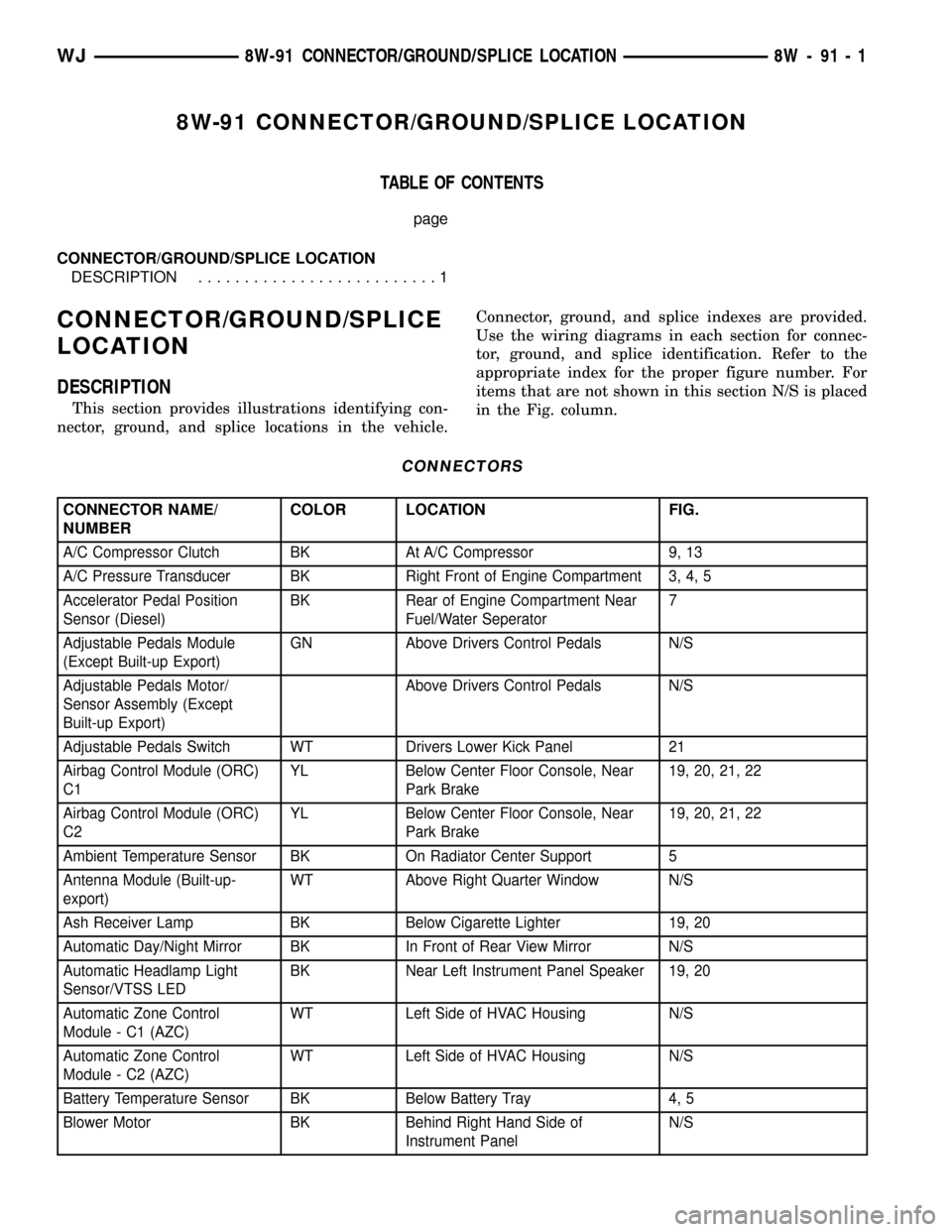
This section provides illustrations identifying con-
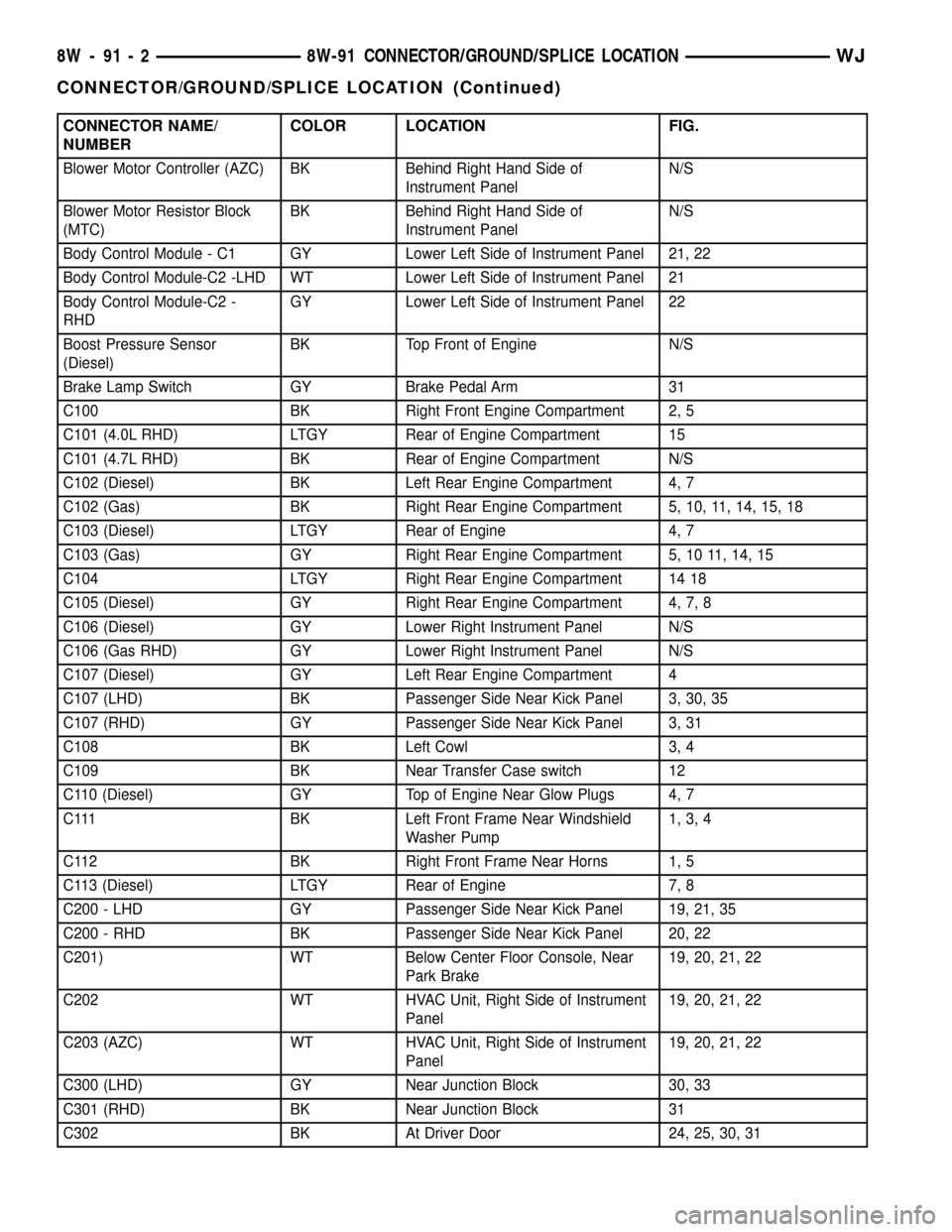
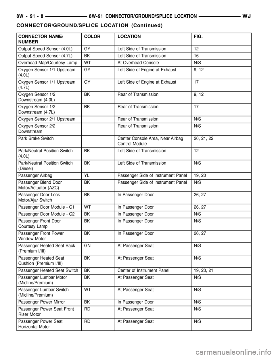
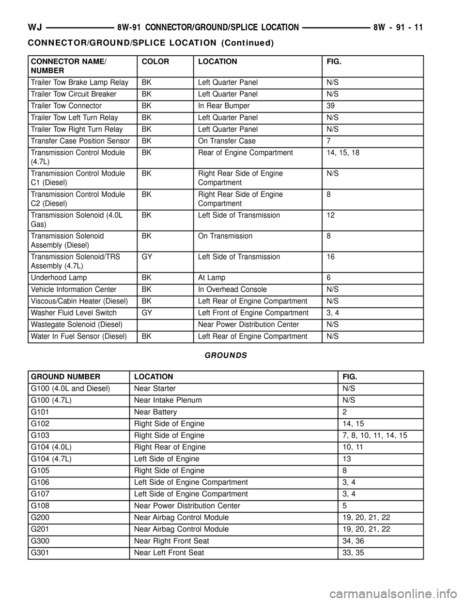
nector, ground, and splice locations in the vehicle.Connector, ground, and splice indexes are provided.
Use the wiring diagrams in each section for connec-
tor, ground, and splice identification. Refer to the
appropriate index for the proper figure number. For
items that are not shown in this section N/S is placed
in the Fig. column.
CONNECTORS
CONNECTOR NAME/
NUMBERCOLOR LOCATION FIG.
A/C Compressor Clutch BK At A/C Compressor 9, 13
A/C Pressure Transducer BK Right Front of Engine Compartment 3, 4, 5
Accelerator Pedal Position
Sensor (Diesel)BK Rear of Engine Compartment Near
Fuel/Water Seperator7
Adjustable Pedals Module
(Except Built-up Export)GN Above Drivers Control Pedals N/S
Adjustable Pedals Motor/
Sensor Assembly (Except
Built-up Export)Above Drivers Control Pedals N/S
Adjustable Pedals Switch WT Drivers Lower Kick Panel 21
Airbag Control Module (ORC)
C1YL Below Center Floor Console, Near
Park Brake19, 20, 21, 22
Airbag Control Module (ORC)
C2YL Below Center Floor Console, Near
Park Brake19, 20, 21, 22
Ambient Temperature Sensor BK On Radiator Center Support 5
Antenna Module (Built-up-
export)WT Above Right Quarter Window N/S
Ash Receiver Lamp BK Below Cigarette Lighter 19, 20
Automatic Day/Night Mirror BK In Front of Rear View Mirror N/S
Automatic Headlamp Light
Sensor/VTSS LEDBK Near Left Instrument Panel Speaker 19, 20
Automatic Zone Control
Module - C1 (AZC)WT Left Side of HVAC Housing N/S
Automatic Zone Control
Module - C2 (AZC)WT Left Side of HVAC Housing N/S
Battery Temperature Sensor BK Below Battery Tray 4, 5
Blower Motor BK Behind Right Hand Side of
Instrument PanelN/S
WJ8W-91 CONNECTOR/GROUND/SPLICE LOCATION 8W - 91 - 1
Page 1177 of 2199

CONNECTOR NAME/
NUMBERCOLOR LOCATION FIG.
Blower Motor Controller (AZC) BK Behind Right Hand Side of
Instrument PanelN/S
Blower Motor Resistor Block
(MTC)BK Behind Right Hand Side of
Instrument PanelN/S
Body Control Module - C1 GY Lower Left Side of Instrument Panel 21, 22
Body Control Module-C2 -LHD WT Lower Left Side of Instrument Panel 21
Body Control Module-C2 -
RHDGY Lower Left Side of Instrument Panel 22
Boost Pressure Sensor
(Diesel)BK Top Front of Engine N/S
Brake Lamp Switch GY Brake Pedal Arm 31
C100 BK Right Front Engine Compartment 2, 5
C101 (4.0L RHD) LTGY Rear of Engine Compartment 15
C101 (4.7L RHD) BK Rear of Engine Compartment N/S
C102 (Diesel) BK Left Rear Engine Compartment 4, 7
C102 (Gas) BK Right Rear Engine Compartment 5, 10, 11, 14, 15, 18
C103 (Diesel) LTGY Rear of Engine 4, 7
C103 (Gas) GY Right Rear Engine Compartment 5, 10 11, 14, 15
C104 LTGY Right Rear Engine Compartment 14 18
C105 (Diesel) GY Right Rear Engine Compartment 4, 7, 8
C106 (Diesel) GY Lower Right Instrument Panel N/S
C106 (Gas RHD) GY Lower Right Instrument Panel N/S
C107 (Diesel) GY Left Rear Engine Compartment 4
C107 (LHD) BK Passenger Side Near Kick Panel 3, 30, 35
C107 (RHD) GY Passenger Side Near Kick Panel 3, 31
C108 BK Left Cowl 3, 4
C109 BK Near Transfer Case switch 12
C110 (Diesel) GY Top of Engine Near Glow Plugs 4, 7
C111 BK Left Front Frame Near Windshield
Washer Pump1, 3, 4
C112 BK Right Front Frame Near Horns 1, 5
C113 (Diesel) LTGY Rear of Engine 7, 8
C200 - LHD GY Passenger Side Near Kick Panel 19, 21, 35
C200 - RHD BK Passenger Side Near Kick Panel 20, 22
C201) WT Below Center Floor Console, Near
Park Brake19, 20, 21, 22
C202 WT HVAC Unit, Right Side of Instrument
Panel19, 20, 21, 22
C203 (AZC) WT HVAC Unit, Right Side of Instrument
Panel19, 20, 21, 22
C300 (LHD) GY Near Junction Block 30, 33
C301 (RHD) BK Near Junction Block 31
C302 BK At Driver Door 24, 25, 30, 31
8W - 91 - 2 8W-91 CONNECTOR/GROUND/SPLICE LOCATIONWJ
CONNECTOR/GROUND/SPLICE LOCATION (Continued)
Page 1183 of 2199

CONNECTOR NAME/
NUMBERCOLOR LOCATION FIG.
Output Speed Sensor (4.0L) GY Left Side of Transmission 12
Output Speed Sensor (4.7L) BK Left Side of Transmission 16
Overhead Map/Courtesy Lamp WT At Overhead Console N/S
Oxygen Sensor 1/1 Upstream
(4.0L)GY Left Side of Engine at Exhaust 9, 12
Oxygen Sensor 1/1 Upstream
(4.7L)GY Left Side of Engine at Exhaust 17
Oxygen Sensor 1/2
Downstream (4.0L)BK Rear of Transmission 9, 12
Oxygen Sensor 1/2
Downstream (4.7L)BK Rear of Transmission 17
Oxygen Sensor 2/1 Upstream Rear of Transmission N/S
Oxygen Sensor 2/2
DownstreamRear of Transmission N/S
Park Brake Switch Center Console Area, Near Airbag
Control Module20, 21, 22
Park/Neutral Position Switch
(4.0L)BK Left Side of Transmission 12
Park/Neutral Position Switch
(Diesel)BK Left Side of Transmission N/S
Passenger Airbag YL Passenger Side of Instrument Panel 19, 20
Passenger Blend Door
Motor/Actuator (AZC)BK Passenger Side of Instrument Panel N/S
Passenger Door Lock
Motor/Ajar SwitchBK In Passenger Door 26, 27
Passenger Door Module - C1 WT In Passenger Door 26, 27
Passenger Door Module - C2 BK In Passenger Door N/S
Passenger Front Door
Courtesy LampBK In Passenger Door N/S
Passenger Front Power
Window MotorBK In Passenger Door 26, 27
Passenger Heated Seat Back
(Premium I/III)GN At Passenger Seat N/S
Passenger Heated Seat
Cushion (Premium I/III)BK At Passenger Seat N/S
Passenger Heated Seat Switch BK Center of Instrument Panel 19, 20, 21
Passenger Lumbar Motor
(Midline/Premium)BK At Passenger Seat N/S
Passenger Lumbar Switch
(Midline/Premium)WT At Passenger Seat N/S
Passenger Power Mirror BK In Passenger Door N/S
Passenger Power Seat Front
Riser MotorRD At Passenger Seat N/S
Passenger Power Seat
Horizontal MotorRD At Passenger Seat N/S
8W - 91 - 8 8W-91 CONNECTOR/GROUND/SPLICE LOCATIONWJ
CONNECTOR/GROUND/SPLICE LOCATION (Continued)
Page 1186 of 2199

CONNECTOR NAME/
NUMBERCOLOR LOCATION FIG.
Trailer Tow Brake Lamp Relay BK Left Quarter Panel N/S
Trailer Tow Circuit Breaker BK Left Quarter Panel N/S
Trailer Tow Connector BK In Rear Bumper 39
Trailer Tow Left Turn Relay BK Left Quarter Panel N/S
Trailer Tow Right Turn Relay BK Left Quarter Panel N/S
Transfer Case Position Sensor BK On Transfer Case 7
Transmission Control Module
(4.7L)BK Rear of Engine Compartment 14, 15, 18
Transmission Control Module
C1 (Diesel)BK Right Rear Side of Engine
CompartmentN/S
Transmission Control Module
C2 (Diesel)BK Right Rear Side of Engine
Compartment8
Transmission Solenoid (4.0L
Gas)BK Left Side of Transmission 12
Transmission Solenoid
Assembly (Diesel)BK On Transmission 8
Transmission Solenoid/TRS
Assembly (4.7L)GY Left Side of Transmission 16
Underhood Lamp BK At Lamp 6
Vehicle Information Center BK In Overhead Console N/S
Viscous/Cabin Heater (Diesel) BK Left Rear of Engine Compartment N/S
Washer Fluid Level Switch GY Left Front of Engine Compartment 3, 4
Wastegate Solenoid (Diesel) Near Power Distribution Center N/S
Water In Fuel Sensor (Diesel) BK Left Rear of Engine Compartment N/S
GROUNDS
GROUND NUMBER LOCATION FIG.
G100 (4.0L and Diesel) Near Starter N/S
G100 (4.7L) Near Intake Plenum N/S
G101 Near Battery 2
G102 Right Side of Engine 14, 15
G103 Right Side of Engine 7, 8, 10, 11, 14, 15
G104 (4.0L) Right Rear of Engine 10, 11
G104 (4.7L) Left Side of Engine 13
G105 Right Side of Engine 8
G106 Left Side of Engine Compartment 3, 4
G107 Left Side of Engine Compartment 3, 4
G108 Near Power Distribution Center 5
G200 Near Airbag Control Module 19, 20, 21, 22
G201 Near Airbag Control Module 19, 20, 21, 22
G300 Near Right Front Seat 34, 36
G301 Near Left Front Seat 33, 35
WJ8W-91 CONNECTOR/GROUND/SPLICE LOCATION 8W - 91 - 11
CONNECTOR/GROUND/SPLICE LOCATION (Continued)
Page 1583 of 2199

ADJUSTMENTS - BRAKE TRANSMISSION
SHIFT INTERLOCK
The park interlock cable is part of the brake/shift
lever interlock system. Correct cable adjustment is
important to proper interlock operation. The gear
shift and park lock cables must both be correctly
adjusted in order to shift out of PARK.
ADJUSTMENT PROCEDURE
(1) Remove floor console as necessary for access to
the brake transmission shift interlock cable. (Refer to
23 - BODY/INTERIOR/FLOOR CONSOLE -
REMOVAL)
(2) Shift the transmission into the PARK position.
(3) Turn ignition switch to LOCK position.Be
sure ignition key cylinder is in the LOCK posi-
tion. Cable will not adjust correctly in any
other position.
(4) Pull cable lock button up to release cable (Fig.
72).
(5) Ensure that the cable is free to self-adjust by
pushing cable rearward and releasing.
(6) Push lock button down until it snaps in place.
BTSI FUNCTION CHECK
(1) Verify removal of ignition key allowed in PARK
position only.
(2) When the shift lever is in PARK, and the shift
handle push-button is in the out position, the igni-
tion key cylinder should rotate freely from off to lock.
When the shifter is in any other position, the ignition
key should not rotate from off to lock.
(3) Shifting out of PARK should be possible when
the ignition key cylinder is in the off position.
(4) Shifting out of PARK should not be possible
while applying normal push-button force, and igni-
tion key cylinder is in the run or start positions,
unless the foot brake pedal is depressed approxi-
mately 1/2 inch (12mm).
(5) Shifting out of PARK should not be possible
when the ignition key cylinder is in the accessory or
lock position.
(6) Shifting between any gear and NEUTRAL, or
PARK, may be done without depressing foot brake
with ignition switch in run or start positions.
(7) The floor shifter lever and gate positions
should be in alignment with all transmission detent
positions.
Fig. 72 Brake Transmission Shift Interlock Cable
1 - SHIFT MECHANISM 4 - STEERING COLUMN ASSEMBLY
2 - SHIFTER BTSI LEVER 5 - INTERLOCK CABLE
3 - ADJUSTMENT CLIP
21 - 64 AUTOMATIC TRANSMISSION - 42REWJ
BRAKE TRANSMISSION SHIFT INTERLOCK MECHANISM (Continued)
Page 1598 of 2199

(3) Remove the shift cable eyelet from the trans-
mission manual shift lever (Fig. 103).
(4) Remove shift cable from the cable support
bracket.
(5) Lower vehicle.
(6) Remove necessary console parts for access to
shift lever assembly and shift cable. (Refer to 23 -
BODY/INTERIOR/FLOOR CONSOLE - REMOVAL)
(7) Disconnect cable at shift lever and shifter
assembly bracket (Fig. 104).
(8) Remove the nuts holding the shift cable seal
plate to the floor pan (Fig. 105).
(9) Pull cable through floor panel opening.(10) Remove shift cable from vehicle.
INSTALLATION
(1) Route cable through hole in floor pan.
(2) Install seal plate to studs in floor pan.
(3) Install nuts to hold seal plate to floor pan.
Tighten nuts to 7 N´m (65 in.lbs.).
(4) Install the shift cable to the shifter assembly
bracket. Push cable into the bracket until secure.
(5) Place the floor shifter lever in PARK position.
(6) Loosen the adjustment screw on the shift cable.
(7) Snap the shift cable onto the shift lever pin.
(8) Raise the vehicle.
(9) Install the shift cable to the shift cable support
bracket.
(10) Shift the transmission into PARK. PARK is
the rearmost detent position on the transmission
manual shift lever.
(11) Snap the shift cable onto the transmission
manual shift lever.
(12) Lower vehicle.
(13) Verify that the shift lever is in the PARK posi-
tion.
(14) Tighten the adjustment screw to 7 N´m (65
in.lbs.).
(15) Verify correct shifter operation.
(16) Install any console parts removed for access to
shift lever assembly and shift cable. (Refer to 23 -
BODY/INTERIOR/FLOOR CONSOLE - INSTALLA-
TION)
ADJUSTMENTS - GEARSHIFT CABLE
Check adjustment by starting the engine in PARK
and NEUTRAL. Adjustment is CORRECT if the
engine starts only in these positions. Adjustment is
Fig. 103 Remove Shift Cable From Transmission
1 - SHIFT CABLE
2 - MANUAL LEVER
3 - MANUAL LEVER
Fig. 104 Transmission Shift Cable at Shifter
1 - SHIFT LEVER PIN
2 - ADJUSTMENT SCREW
3 - SHIFT CABLE
4 - SHIFTER ASSEMBLY BRACKET
Fig. 105 Shift Cables at Floor Pan
1 - SEAL PLATES
2 - TRANSMISSION SHIFT CABLE
3 - TRANSFER CASE SHIFT CABLE
WJAUTOMATIC TRANSMISSION - 42RE 21 - 79
GEARSHIFT CABLE (Continued)