Park neutral position switch JEEP GRAND CHEROKEE 2002 WJ / 2.G Owner's Guide
[x] Cancel search | Manufacturer: JEEP, Model Year: 2002, Model line: GRAND CHEROKEE, Model: JEEP GRAND CHEROKEE 2002 WJ / 2.GPages: 2199, PDF Size: 76.01 MB
Page 1155 of 2199
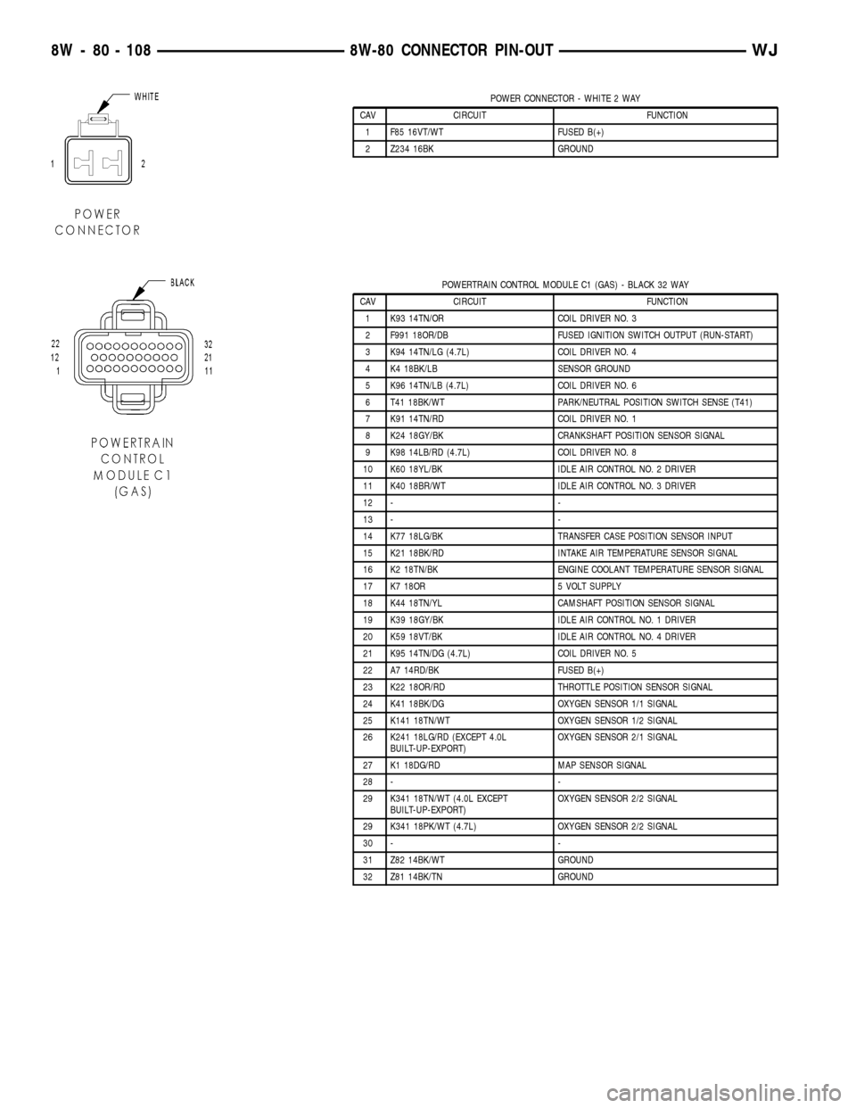
POWER CONNECTOR - WHITE 2 WAY
CAV CIRCUIT FUNCTION
1 F85 16VT/WT FUSED B(+)
2 Z234 16BK GROUND
POWERTRAIN CONTROL MODULE C1 (GAS) - BLACK 32 WAY
CAV CIRCUIT FUNCTION
1 K93 14TN/OR COIL DRIVER NO. 3
2 F991 18OR/DB FUSED IGNITION SWITCH OUTPUT (RUN-START)
3 K94 14TN/LG (4.7L) COIL DRIVER NO. 4
4 K4 18BK/LB SENSOR GROUND
5 K96 14TN/LB (4.7L) COIL DRIVER NO. 6
6 T41 18BK/WT PARK/NEUTRAL POSITION SWITCH SENSE (T41)
7 K91 14TN/RD COIL DRIVER NO. 1
8 K24 18GY/BK CRANKSHAFT POSITION SENSOR SIGNAL
9 K98 14LB/RD (4.7L) COIL DRIVER NO. 8
10 K60 18YL/BK IDLE AIR CONTROL NO. 2 DRIVER
11 K40 18BR/WT IDLE AIR CONTROL NO. 3 DRIVER
12 - -
13 - -
14 K77 18LG/BK TRANSFER CASE POSITION SENSOR INPUT
15 K21 18BK/RD INTAKE AIR TEMPERATURE SENSOR SIGNAL
16 K2 18TN/BK ENGINE COOLANT TEMPERATURE SENSOR SIGNAL
17 K7 18OR 5 VOLT SUPPLY
18 K44 18TN/YL CAMSHAFT POSITION SENSOR SIGNAL
19 K39 18GY/BK IDLE AIR CONTROL NO. 1 DRIVER
20 K59 18VT/BK IDLE AIR CONTROL NO. 4 DRIVER
21 K95 14TN/DG (4.7L) COIL DRIVER NO. 5
22 A7 14RD/BK FUSED B(+)
23 K22 18OR/RD THROTTLE POSITION SENSOR SIGNAL
24 K41 18BK/DG OXYGEN SENSOR 1/1 SIGNAL
25 K141 18TN/WT OXYGEN SENSOR 1/2 SIGNAL
26 K241 18LG/RD (EXCEPT 4.0L
BUILT-UP-EXPORT)OXYGEN SENSOR 2/1 SIGNAL
27 K1 18DG/RD MAP SENSOR SIGNAL
28 - -
29 K341 18TN/WT (4.0L EXCEPT
BUILT-UP-EXPORT)OXYGEN SENSOR 2/2 SIGNAL
29 K341 18PK/WT (4.7L) OXYGEN SENSOR 2/2 SIGNAL
30 - -
31 Z82 14BK/WT GROUND
32 Z81 14BK/TN GROUND
8W - 80 - 108 8W-80 CONNECTOR PIN-OUTWJ
Page 1166 of 2199
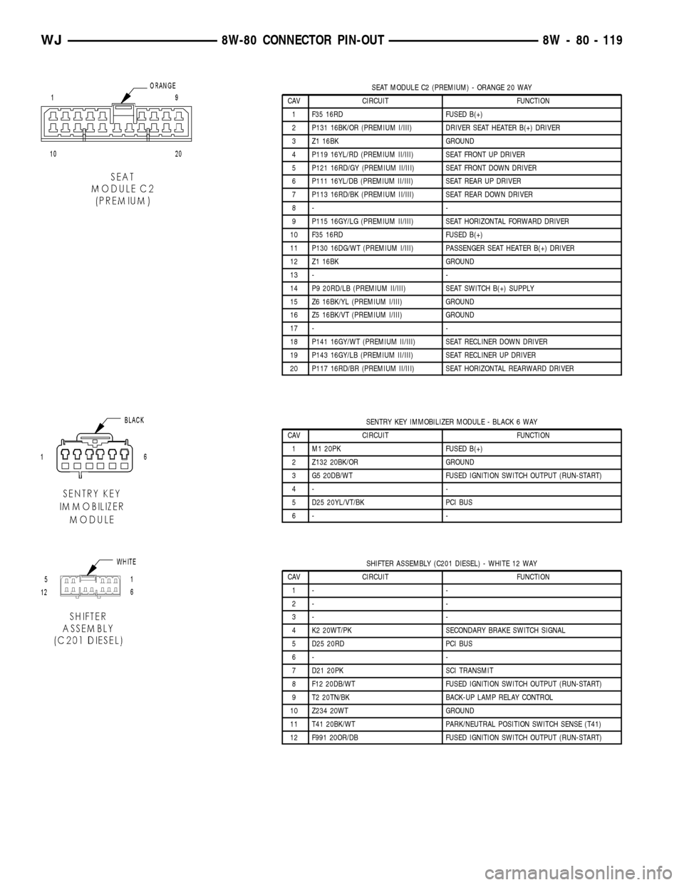
SEAT MODULE C2 (PREMIUM) - ORANGE 20 WAY
CAV CIRCUIT FUNCTION
1 F35 16RD FUSED B(+)
2 P131 16BK/OR (PREMIUM I/III) DRIVER SEAT HEATER B(+) DRIVER
3 Z1 16BK GROUND
4 P119 16YL/RD (PREMIUM II/III) SEAT FRONT UP DRIVER
5 P121 16RD/GY (PREMIUM II/III) SEAT FRONT DOWN DRIVER
6 P111 16YL/DB (PREMIUM II/III) SEAT REAR UP DRIVER
7 P113 16RD/BK (PREMIUM II/III) SEAT REAR DOWN DRIVER
8- -
9 P115 16GY/LG (PREMIUM II/III) SEAT HORIZONTAL FORWARD DRIVER
10 F35 16RD FUSED B(+)
11 P130 16DG/WT (PREMIUM I/III) PASSENGER SEAT HEATER B(+) DRIVER
12 Z1 16BK GROUND
13 - -
14 P9 20RD/LB (PREMIUM II/III) SEAT SWITCH B(+) SUPPLY
15 Z6 16BK/YL (PREMIUM I/III) GROUND
16 Z5 16BK/VT (PREMIUM I/III) GROUND
17 - -
18 P141 16GY/WT (PREMIUM II/III) SEAT RECLINER DOWN DRIVER
19 P143 16GY/LB (PREMIUM II/III) SEAT RECLINER UP DRIVER
20 P117 16RD/BR (PREMIUM II/III) SEAT HORIZONTAL REARWARD DRIVER
SENTRY KEY IMMOBILIZER MODULE - BLACK 6 WAY
CAV CIRCUIT FUNCTION
1 M1 20PK FUSED B(+)
2 Z132 20BK/OR GROUND
3 G5 20DB/WT FUSED IGNITION SWITCH OUTPUT (RUN-START)
4- -
5 D25 20YL/VT/BK PCI BUS
6- -
SHIFTER ASSEMBLY (C201 DIESEL) - WHITE 12 WAY
CAV CIRCUIT FUNCTION
1- -
2- -
3- -
4 K2 20WT/PK SECONDARY BRAKE SWITCH SIGNAL
5 D25 20RD PCI BUS
6- -
7 D21 20PK SCI TRANSMIT
8 F12 20DB/WT FUSED IGNITION SWITCH OUTPUT (RUN-START)
9 T2 20TN/BK BACK-UP LAMP RELAY CONTROL
10 Z234 20WT GROUND
11 T41 20BK/WT PARK/NEUTRAL POSITION SWITCH SENSE (T41)
12 F991 20OR/DB FUSED IGNITION SWITCH OUTPUT (RUN-START)
WJ8W-80 CONNECTOR PIN-OUT 8W - 80 - 119
Page 1172 of 2199
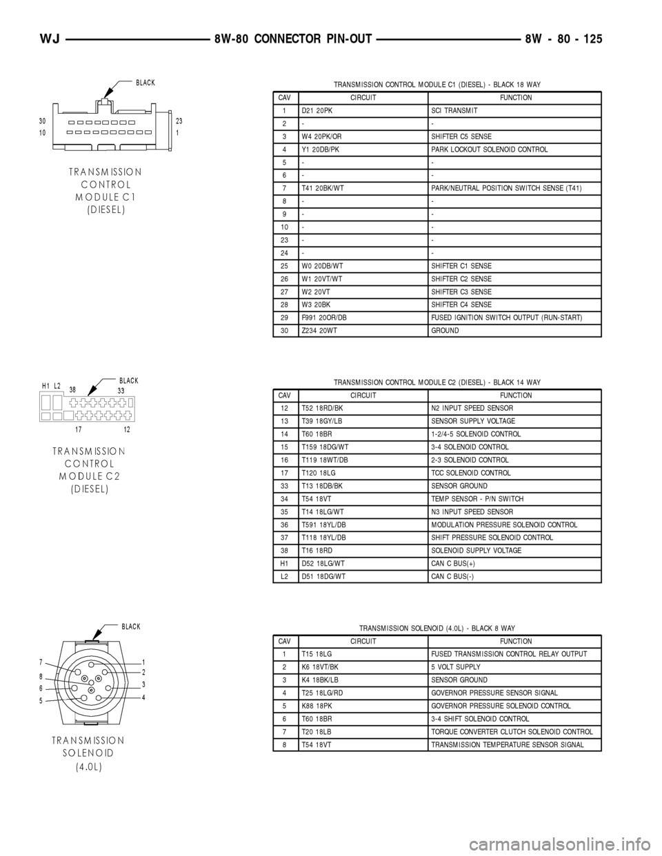
TRANSMISSION CONTROL MODULE C1 (DIESEL) - BLACK 18 WAY
CAV CIRCUIT FUNCTION
1 D21 20PK SCI TRANSMIT
2- -
3 W4 20PK/OR SHIFTER C5 SENSE
4 Y1 20DB/PK PARK LOCKOUT SOLENOID CONTROL
5- -
6- -
7 T41 20BK/WT PARK/NEUTRAL POSITION SWITCH SENSE (T41)
8- -
9- -
10 - -
23 - -
24 - -
25 W0 20DB/WT SHIFTER C1 SENSE
26 W1 20VT/WT SHIFTER C2 SENSE
27 W2 20VT SHIFTER C3 SENSE
28 W3 20BK SHIFTER C4 SENSE
29 F991 20OR/DB FUSED IGNITION SWITCH OUTPUT (RUN-START)
30 Z234 20WT GROUND
TRANSMISSION CONTROL MODULE C2 (DIESEL) - BLACK 14 WAY
CAV CIRCUIT FUNCTION
12 T52 18RD/BK N2 INPUT SPEED SENSOR
13 T39 18GY/LB SENSOR SUPPLY VOLTAGE
14 T60 18BR 1-2/4-5 SOLENOID CONTROL
15 T159 18DG/WT 3-4 SOLENOID CONTROL
16 T119 18WT/DB 2-3 SOLENOID CONTROL
17 T120 18LG TCC SOLENOID CONTROL
33 T13 18DB/BK SENSOR GROUND
34 T54 18VT TEMP SENSOR - P/N SWITCH
35 T14 18LG/WT N3 INPUT SPEED SENSOR
36 T591 18YL/DB MODULATION PRESSURE SOLENOID CONTROL
37 T118 18YL/DB SHIFT PRESSURE SOLENOID CONTROL
38 T16 18RD SOLENOID SUPPLY VOLTAGE
H1 D52 18LG/WT CAN C BUS(+)
L2 D51 18DG/WT CAN C BUS(-)
TRANSMISSION SOLENOID (4.0L) - BLACK 8 WAY
CAV CIRCUIT FUNCTION
1 T15 18LG FUSED TRANSMISSION CONTROL RELAY OUTPUT
2 K6 18VT/BK 5 VOLT SUPPLY
3 K4 18BK/LB SENSOR GROUND
4 T25 18LG/RD GOVERNOR PRESSURE SENSOR SIGNAL
5 K88 18PK GOVERNOR PRESSURE SOLENOID CONTROL
6 T60 18BR 3-4 SHIFT SOLENOID CONTROL
7 T20 18LB TORQUE CONVERTER CLUTCH SOLENOID CONTROL
8 T54 18VT TRANSMISSION TEMPERATURE SENSOR SIGNAL
WJ8W-80 CONNECTOR PIN-OUT 8W - 80 - 125
Page 1173 of 2199
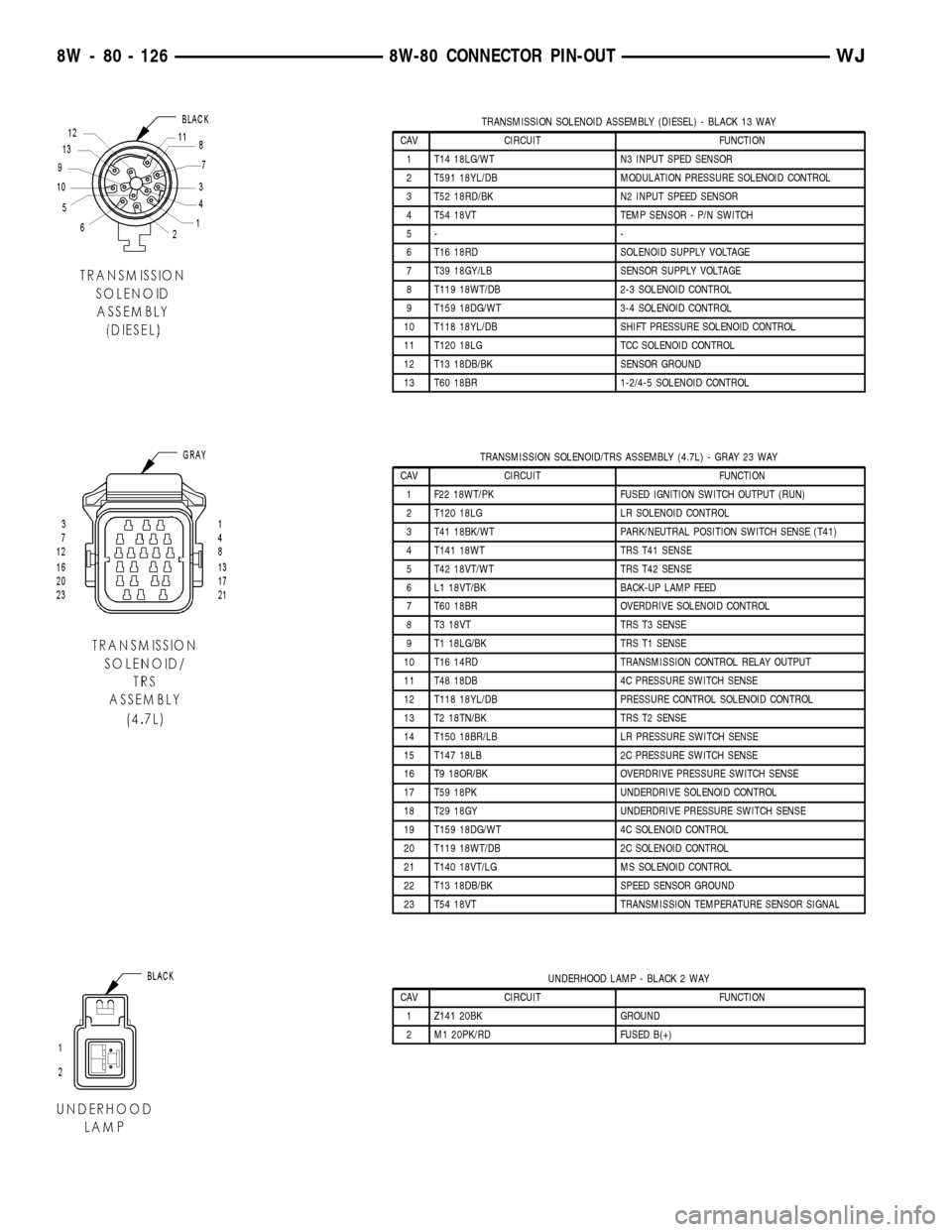
TRANSMISSION SOLENOID ASSEMBLY (DIESEL) - BLACK 13 WAY
CAV CIRCUIT FUNCTION
1 T14 18LG/WT N3 INPUT SPED SENSOR
2 T591 18YL/DB MODULATION PRESSURE SOLENOID CONTROL
3 T52 18RD/BK N2 INPUT SPEED SENSOR
4 T54 18VT TEMP SENSOR - P/N SWITCH
5- -
6 T16 18RD SOLENOID SUPPLY VOLTAGE
7 T39 18GY/LB SENSOR SUPPLY VOLTAGE
8 T119 18WT/DB 2-3 SOLENOID CONTROL
9 T159 18DG/WT 3-4 SOLENOID CONTROL
10 T118 18YL/DB SHIFT PRESSURE SOLENOID CONTROL
11 T120 18LG TCC SOLENOID CONTROL
12 T13 18DB/BK SENSOR GROUND
13 T60 18BR 1-2/4-5 SOLENOID CONTROL
TRANSMISSION SOLENOID/TRS ASSEMBLY (4.7L) - GRAY 23 WAY
CAV CIRCUIT FUNCTION
1 F22 18WT/PK FUSED IGNITION SWITCH OUTPUT (RUN)
2 T120 18LG LR SOLENOID CONTROL
3 T41 18BK/WT PARK/NEUTRAL POSITION SWITCH SENSE (T41)
4 T141 18WT TRS T41 SENSE
5 T42 18VT/WT TRS T42 SENSE
6 L1 18VT/BK BACK-UP LAMP FEED
7 T60 18BR OVERDRIVE SOLENOID CONTROL
8 T3 18VT TRS T3 SENSE
9 T1 18LG/BK TRS T1 SENSE
10 T16 14RD TRANSMISSION CONTROL RELAY OUTPUT
11 T48 18DB 4C PRESSURE SWITCH SENSE
12 T118 18YL/DB PRESSURE CONTROL SOLENOID CONTROL
13 T2 18TN/BK TRS T2 SENSE
14 T150 18BR/LB LR PRESSURE SWITCH SENSE
15 T147 18LB 2C PRESSURE SWITCH SENSE
16 T9 18OR/BK OVERDRIVE PRESSURE SWITCH SENSE
17 T59 18PK UNDERDRIVE SOLENOID CONTROL
18 T29 18GY UNDERDRIVE PRESSURE SWITCH SENSE
19 T159 18DG/WT 4C SOLENOID CONTROL
20 T119 18WT/DB 2C SOLENOID CONTROL
21 T140 18VT/LG MS SOLENOID CONTROL
22 T13 18DB/BK SPEED SENSOR GROUND
23 T54 18VT TRANSMISSION TEMPERATURE SENSOR SIGNAL
UNDERHOOD LAMP - BLACK 2 WAY
CAV CIRCUIT FUNCTION
1 Z141 20BK GROUND
2 M1 20PK/RD FUSED B(+)
8W - 80 - 126 8W-80 CONNECTOR PIN-OUTWJ
Page 1183 of 2199
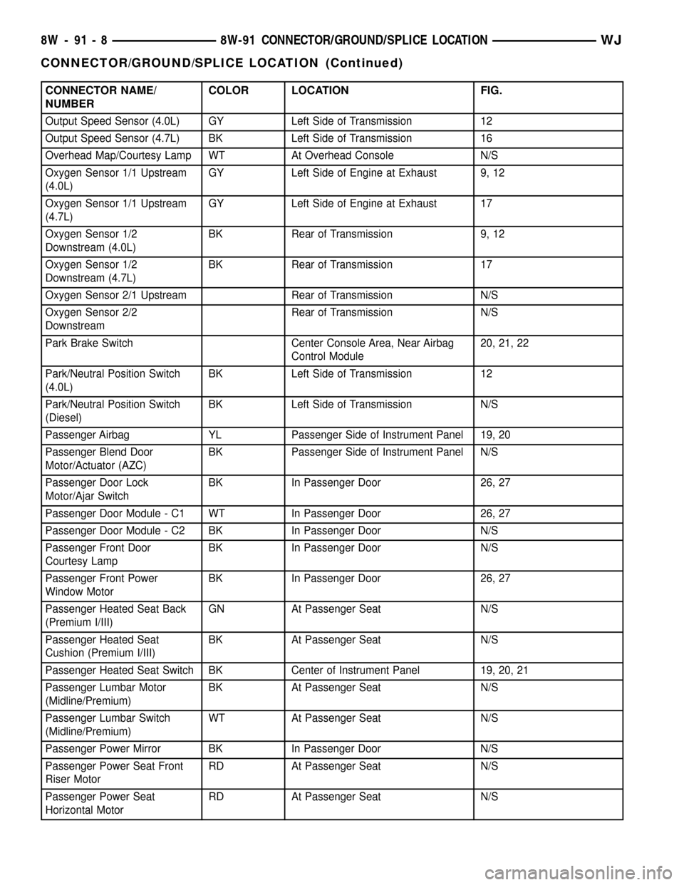
CONNECTOR NAME/
NUMBERCOLOR LOCATION FIG.
Output Speed Sensor (4.0L) GY Left Side of Transmission 12
Output Speed Sensor (4.7L) BK Left Side of Transmission 16
Overhead Map/Courtesy Lamp WT At Overhead Console N/S
Oxygen Sensor 1/1 Upstream
(4.0L)GY Left Side of Engine at Exhaust 9, 12
Oxygen Sensor 1/1 Upstream
(4.7L)GY Left Side of Engine at Exhaust 17
Oxygen Sensor 1/2
Downstream (4.0L)BK Rear of Transmission 9, 12
Oxygen Sensor 1/2
Downstream (4.7L)BK Rear of Transmission 17
Oxygen Sensor 2/1 Upstream Rear of Transmission N/S
Oxygen Sensor 2/2
DownstreamRear of Transmission N/S
Park Brake Switch Center Console Area, Near Airbag
Control Module20, 21, 22
Park/Neutral Position Switch
(4.0L)BK Left Side of Transmission 12
Park/Neutral Position Switch
(Diesel)BK Left Side of Transmission N/S
Passenger Airbag YL Passenger Side of Instrument Panel 19, 20
Passenger Blend Door
Motor/Actuator (AZC)BK Passenger Side of Instrument Panel N/S
Passenger Door Lock
Motor/Ajar SwitchBK In Passenger Door 26, 27
Passenger Door Module - C1 WT In Passenger Door 26, 27
Passenger Door Module - C2 BK In Passenger Door N/S
Passenger Front Door
Courtesy LampBK In Passenger Door N/S
Passenger Front Power
Window MotorBK In Passenger Door 26, 27
Passenger Heated Seat Back
(Premium I/III)GN At Passenger Seat N/S
Passenger Heated Seat
Cushion (Premium I/III)BK At Passenger Seat N/S
Passenger Heated Seat Switch BK Center of Instrument Panel 19, 20, 21
Passenger Lumbar Motor
(Midline/Premium)BK At Passenger Seat N/S
Passenger Lumbar Switch
(Midline/Premium)WT At Passenger Seat N/S
Passenger Power Mirror BK In Passenger Door N/S
Passenger Power Seat Front
Riser MotorRD At Passenger Seat N/S
Passenger Power Seat
Horizontal MotorRD At Passenger Seat N/S
8W - 91 - 8 8W-91 CONNECTOR/GROUND/SPLICE LOCATIONWJ
CONNECTOR/GROUND/SPLICE LOCATION (Continued)
Page 1521 of 2199

STANDARD PROCEDURE - FLUID AND
FILTER REPLACEMENT................71
STANDARD PROCEDURE - TRANSMISSION
FILL................................72
FRONT CLUTCH
DESCRIPTION.........................73
OPERATION...........................74
DISASSEMBLY.........................74
INSPECTION..........................74
ASSEMBLY............................74
FRONT SERVO
DESCRIPTION.........................77
OPERATION...........................77
DISASSEMBLY.........................77
CLEANING............................77
INSPECTION..........................77
ASSEMBLY............................77
GEARSHIFT CABLE
DIAGNOSIS AND TESTING - GEARSHIFT
CABLE..............................78
REMOVAL.............................78
INSTALLATION.........................79
ADJUSTMENTS - GEARSHIFT CABLE.......79
OIL PUMP
DESCRIPTION.........................80
OPERATION...........................80
STANDARD PROCEDURE - OIL PUMP
VOLUME CHECK......................81
DISASSEMBLY.........................81
CLEANING............................83
INSPECTION..........................83
ASSEMBLY............................83
OUTPUT SHAFT FRONT BEARING
REMOVAL.............................85
INSTALLATION.........................85
OUTPUT SHAFT REAR BEARING
REMOVAL.............................85
INSTALLATION.........................85
OVERDRIVE CLUTCH
DESCRIPTION.........................86
OPERATION...........................86
OVERDRIVE OFF SWITCH
DESCRIPTION.........................86
OPERATION...........................86
DIAGNOSIS AND TESTING - OVERDRIVE
ELECTRICAL CONTROLS...............87
OVERDRIVE UNIT
REMOVAL.............................87
DISASSEMBLY.........................88
CLEANING............................95
INSPECTION..........................95
ASSEMBLY............................95
INSTALLATION........................104
OVERRUNNING CLUTCH CAM/OVERDRIVE
PISTON RETAINER
DESCRIPTION........................105
OPERATION..........................105DISASSEMBLY........................106
CLEANING...........................106
INSPECTION.........................106
ASSEMBLY...........................106
PARK LOCK CABLE
REMOVAL............................108
INSTALLATION........................108
PARK/NEUTRAL POSITION SWITCH
DIAGNOSIS AND TESTING - PARK/NEUTRAL
POSITION SWITCH...................109
REMOVAL............................109
INSTALLATION........................109
PISTONS
DESCRIPTION........................110
OPERATION..........................110
PLANETARY GEARTRAIN/OUTPUT SHAFT
DESCRIPTION........................112
OPERATION..........................112
DISASSEMBLY........................112
INSPECTION..........................113
ASSEMBLY...........................113
REAR CLUTCH
DESCRIPTION........................118
OPERATION..........................118
DISASSEMBLY........................119
CLEANING...........................119
INSPECTION.........................120
ASSEMBLY...........................120
REAR SERVO
DESCRIPTION........................122
OPERATION..........................122
DISASSEMBLY........................122
CLEANING...........................122
ASSEMBLY...........................123
SHIFT MECHANISM
DESCRIPTION........................123
OPERATION..........................123
REMOVAL............................123
INSTALLATION........................125
SOLENOID
DESCRIPTION........................125
OPERATION..........................126
SPEED SENSOR
DESCRIPTION........................126
OPERATION..........................126
THROTTLE VALVE CABLE
DESCRIPTION........................126
ADJUSTMENTS - TRANSMISSION THROTTLE
VALVE CABLE.......................126
TORQUE CONVERTER
DESCRIPTION........................128
OPERATION..........................132
REMOVAL............................133
INSTALLATION........................133
TORQUE CONVERTER DRAINBACK VALVE
DESCRIPTION........................134
OPERATION..........................134
21 - 2 AUTOMATIC TRANSMISSION - 42REWJ
Page 1524 of 2199

IDENTIFICATION
Transmission identification numbers are stamped
on the left side of the case just above the oil pan gas-
ket surface (Fig. 2). Refer to this information when
ordering replacement parts.
GEAR RATIOS The 42RE gear ratios are:
1st.................................2.74:1
2nd................................1.54:1
3rd.................................1.00:1
4th.................................0.69:1
Rev.................................2.21:1
OPERATION
The application of each driving or holding compo-
nent is controlled by the valve body based upon the
manual lever position, throttle pressure, and gover-
nor pressure. The governor pressure is a variable
pressure input to the valve body and is one of the
signals that a shift is necessary. First through fourth
gear are obtained by selectively applying and releas-
ing the different clutches and bands. Engine power is
thereby routed to the various planetary gear assem-
blies which combine with the overrunning clutch
assemblies to generate the different gear ratios. The
torque converter clutch is hydraulically applied and
is released when fluid is vented from the hydraulic
circuit by the torque converter control (TCC) solenoid
on the valve body. The torque converter clutch is con-
trolled by the Powertrain Control Module (PCM). The
torque converter clutch engages in fourth gear, and
in third gear under various conditions, such as when
the O/D switch is OFF, when the vehicle is cruising
on a level surface after the vehicle has warmed up.
The torque converter clutch will disengage momen-
tarily when an increase in engine load is sensed by
the PCM, such as when the vehicle begins to go
uphill or the throttle pressure is increased. The
torque converter clutch feature increases fuel econ-
omy and reduces the transmission fluid temperature.
Since the overdrive clutch is applied in fourth gear
only and the direct clutch is applied in all ranges
except fourth gear, the transmission operation for
park, neutral, and first through third gear will be
described first. Once these powerflows are described,
the third to fourth shift sequence will be described.
1 - CONVERTER CLUTCH 15 - HOUSING
2 - TORQUE CONVERTER 16 - REAR BEARING
3 - OIL PUMP AND REACTION SHAFT SUPPORT ASSEMBLY 17 - OUTPUT SHAFT
4 - FRONT BAND 18 - SEAL
5 - FRONT CLUTCH 19 - OVERDRIVE OVERRUNNING CLUTCH
6 - DRIVING SHELL 20 - OVERDRIVE PLANETARY GEAR
7 - REAR BAND 21 - DIRECT CLUTCH SPRING
8 - TRANSMISSION OVERRUNNING CLUTCH 22 - OVERDRIVE CLUTCH PISTON
9 - OVERDRIVE UNIT 23 - VALVE BODY ASSEMBLY
10 - PISTON RETAINER 24 - FILTER
11 - OVERDRIVE CLUTCH 25 - FRONT PLANETARY GEAR
12 - DIRECT CLUTCH 26 - REAR CLUTCH
13 - INTERMEDIATE SHAFT 27 - TRANSMISSION
14 - FRONT BEARING 28 - REAR PLANETARY GEAR
Fig. 2 Transmission Part And Serial Number
Location
1 - PART NUMBER
2 - BUILD DATE
3 - SERIAL NUMBER
WJAUTOMATIC TRANSMISSION - 42RE 21 - 5
AUTOMATIC TRANSMISSION - 42RE (Continued)
Page 1544 of 2199
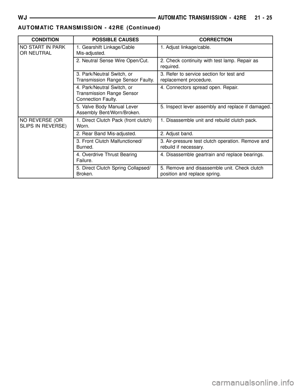
CONDITION POSSIBLE CAUSES CORRECTION
NO START IN PARK
OR NEUTRAL1. Gearshift Linkage/Cable
Mis-adjusted.1. Adjust linkage/cable.
2. Neutral Sense Wire Open/Cut. 2. Check continuity with test lamp. Repair as
required.
3. Park/Neutral Switch, or
Transmission Range Sensor Faulty.3. Refer to service section for test and
replacement procedure.
4. Park/Neutral Switch, or
Transmission Range Sensor
Connection Faulty.4. Connectors spread open. Repair.
5. Valve Body Manual Lever
Assembly Bent/Worn/Broken.5. Inspect lever assembly and replace if damaged.
NO REVERSE (OR
SLIPS IN REVERSE)1. Direct Clutch Pack (front clutch)
Worn.1. Disassemble unit and rebuild clutch pack.
2. Rear Band Mis-adjusted. 2. Adjust band.
3. Front Clutch Malfunctioned/
Burned.3. Air-pressure test clutch operation. Remove and
rebuild if necessary.
4. Overdrive Thrust Bearing
Failure.4. Disassemble geartrain and replace bearings.
5. Direct Clutch Spring Collapsed/
Broken.5. Remove and disassemble unit. Check clutch
position and replace spring.
WJAUTOMATIC TRANSMISSION - 42RE 21 - 25
AUTOMATIC TRANSMISSION - 42RE (Continued)
Page 1546 of 2199

REMOVAL
The overdrive unit can be removed and serviced
separately. It is not necessary to remove the entire
transmission assembly to perform overdrive unit
repairs.
If only the overdrive unit requires service, refer to
Overdrive Removal for proper procedures.
CAUTION: The transmission and torque converter
must be removed as an assembly to avoid compo-
nent damage. The converter driveplate, pump bush-
ing, or oil seal can be damaged if the converter is
left attached to the driveplate during removal. Be
sure to remove the transmission and converter as
an assembly.
(1) Disconnect battery negative cable.
(2) Disconnect and lower or remove necessary
exhaust components.
(3) Disconnect fluid cooler lines at transmission.
(4) Remove starter motor. (Refer to 8 - ELECTRI-
CAL/STARTING/STARTER MOTOR - REMOVAL)
(5) Disconnect and remove crankshaft position sen-
sor. (Refer to 14 - FUEL SYSTEM/FUEL INJEC-
TION/CRANKSHAFT POSITION SENSOR -
REMOVAL) Retain sensor attaching bolts.
CAUTION: The crankshaft position sensor will be
damaged if the transmission is removed, or
installed, while the sensor is still bolted to the
engine block, or transmission (4.0L only). To avoid
damage, be sure to remove the sensor before
removing the transmission.
(6) Remove the bolts holding the bell housing
brace to the transmission.
(7) Remove nut holding the bell housing brace to
the engine to transmission bending brace.
(8) Remove the bell housing brace from the trans-
mission (Fig. 13).
(9) Remove the bolt holding the torque converter
cover to the transmission.
(10) Remove the torque converter cover from the
transmission.
(11) If transmission is being removed for overhaul,
remove transmission oil pan, drain fluid and reinstall
pan.
(12) Remove fill tube bracket bolts and pull tube
out of transmission. Retain fill tube seal. On4x4
models, it will also be necessary to remove bolt
attaching transfer case vent tube to converter hous-
ing.
(13) Rotate crankshaft in clockwise direction until
converter bolts are accessible. Then remove bolts one
at a time. Rotate crankshaft with socket wrench on
dampener bolt.(14) Mark propeller shaft and axle yokes for
assembly alignment. Then disconnect and remove
propeller shaft. On4x4models, remove both propel-
ler shafts.
(15) Disconnect wires from park/neutral position
switch and transmission solenoid.
(16) Disconnect gearshift cable from transmission
manual valve lever (Fig. 14).
Fig. 13 Bell Housing Brace and Converter Cover
1 - Transmission
2 - Torque Converter Cover
3 - Bellhousing Brace
Fig. 14 Transmission Shift Cable
1 - SHIFT CABLE
2 - MANUAL LEVER
3 - MANUAL LEVER
WJAUTOMATIC TRANSMISSION - 42RE 21 - 27
AUTOMATIC TRANSMISSION - 42RE (Continued)
Page 1548 of 2199

(26) Remove bolts holding the upper transmission
bending braces to the torque converter housing and
the overdrive unit (Fig. 20).
(27) Remove all remaining converter housing bolts.
(28) Carefully work transmission and torque con-
verter assembly rearward off engine block dowels.
(29) Hold torque converter in place during trans-
mission removal.
(30) Lower transmission and remove assembly
from under the vehicle.
(31) To remove torque converter, carefully slide
torque converter out of the transmission.
DISASSEMBLY
(1) Clean transmission exterior with steam gun or
with solvent. Wear eye protection during cleaning
operations.
(2) Place transmission in a vertical position.(3) Measure input shaft end play as follows (Fig.
21).
(a) Attach Adapter 8266-6 to Handle 8266-8.
(b) Attach dial indicator C-3339 to Handle
8266-8.
(c) Install the assembled tool onto the input
shaft of the transmission and tighten the retaining
screw on Adapter 8266-6 to secure it to the input
shaft.
(d) Position the dial indicator plunger against a
flat spot on the oil pump and zero the dial indica-
tor.
(e) Move the input shaft in and out. Record the
maximum travel for assembly reference.
(4) Remove shift and throttle levers from valve
body manual lever shaft.
(5) Place transmission in horizontal position.
(6) Remove transmission oil pan and gasket.
(7) Remove filter from valve body (Fig. 22). Keep
filter screws separate from other valve body screws.
Filter screws are longer and should be kept with fil-
ter.
(8) Remove park/neutral position switch.
(9) Remove hex head bolts attaching valve body to
transmission case (Fig. 23). A total of 10 bolts are
used. Note different bolt lengths for assembly refer-
ence.
Fig. 19 Remove NV242 Transfer Case
1 - NV242 TRANSFER CASE
Fig. 20 Remove Upper Transmission Bending
Braces
1 - TRANSMISSION BENDING BRACES
Fig. 21 Checking Input Shaft End Play
1 - TOOL 8266-8
2 - TOOL 8266-6
3 - TOOL C-3339
WJAUTOMATIC TRANSMISSION - 42RE 21 - 29
AUTOMATIC TRANSMISSION - 42RE (Continued)