Transmission pan JEEP GRAND CHEROKEE 2002 WJ / 2.G Owner's Guide
[x] Cancel search | Manufacturer: JEEP, Model Year: 2002, Model line: GRAND CHEROKEE, Model: JEEP GRAND CHEROKEE 2002 WJ / 2.GPages: 2199, PDF Size: 76.01 MB
Page 623 of 2199

(3) Insert the hook formation on the tip of the
wiper arm through the opening in the wiper blade
superstructure ahead of the wiper blade pivot block/
latch unit far enough to engage the pivot block with
the hook (Fig. 10).
(4) Slide the wiper blade pivot block/latch up into
the hook formation on the tip of the wiper arm until
the latch release tab snaps into its locked position.
Latch engagement will be accompanied by an audible
click.
(5) Gently lower the wiper blade onto the glass.
FRONT WIPER MODULE
DESCRIPTION
The front wiper module is secured with four screws
through rubber isolators to the cowl plenum panel
beneath the cowl plenum cover/grille panel (Fig. 11).
The ends of the wiper pivot shafts that protrude
through dedicated openings in the cowl plenum cov-
er/grille panel to drive the wiper arms and blades are
the only visible components of the front wiper mod-
ule. The front wiper module consists of the following
major components:
²Bracket- The front wiper module bracket con-
sists of a long tubular steel main member that has a
stamped pivot bracket formation near each end
where the two wiper pivots are secured. A stamped
steel mounting plate for the wiper motor is secured
with welds near the center of the main member.
²Crank Arm- The front wiper motor crank arm
is a stamped steel unit with a slotted hole on the
driven end that is secured to the wiper motor outputshaft with a nut, and a ball stud secured to the drive
end.
²Linkage- Two stamped steel drive links con-
nect the wiper motor crank arm to the pivot lever
arms. The passenger side drive link has a plastic
socket-type bushing on each end. The driver side
drive link has a plastic socket-type bushing on one
end, and a plastic sleeve-type bushing on the other
end. The socket-type bushing on one end of each
drive link is snap-fit over the ball stud on the lever
arm of its respective pivot. The driver side drive link
sleeve-type bushing end is then fit over the motor
crank arm ball stud, and the other socket-type bush-
ing of the passenger side drive link is snap-fit over
the exposed end of the wiper motor crank arm ball
stud.
²Motor- The front wiper motor is secured with
three screws to the motor mounting plate near the
center of the wiper module bracket. The wiper motor
output shaft passes through a hole in the module
bracket, where a nut secures the wiper motor crank
arm to the motor output shaft. The two-speed perma-
nent magnet wiper motor features an integral trans-
mission, an internal park switch, and an internal
automatic resetting circuit breaker.
²Pivots- The two front wiper pivots are secured
to the ends of the wiper module bracket. The crank
arms that extend from the bottom of the pivot shafts
each have a ball stud on their end. The upper end of
each pivot shaft where the wiper arms will be fas-
tened each has an externally serrated drum with a
threaded stud secured to it.
The front wiper module cannot be adjusted or
repaired. If any component of the module is faulty or
damaged, the entire front wiper module unit must be
replaced. The reinforcement bracket and stud plate
are available for service replacement.OPERATION
The front wiper module operation is controlled by
the battery current inputs received by the wiper
motor from the wiper on/off and wiper high/low
relays. The wiper motor speed is controlled by cur-
rent flow to either the low speed or the high speed
set of brushes. The park switch is a single pole, sin-
gle throw, momentary switch within the wiper motor
that is mechanically actuated by the wiper motor
transmission components. The park switch alter-
nately closes the wiper park switch sense circuit to
ground or to battery current, depending upon the
position of the wipers on the glass. This feature
allows the motor to complete its current wipe cycle
after the wiper system has been turned Off, and to
park the wiper blades in the lowest portion of the
wipe pattern. The automatic resetting circuit breaker
protects the motor from overloads. The wiper motor
Fig. 11 Front Wiper Module
1 - FRONT WIPER MODULE
2 - SCREW (4)
3 - WIRE HARNESS CONNECTOR
4 - LOWER COWL PLENUM PANEL
8R - 16 FRONT WIPERS/WASHERSWJ
FRONT WIPER BLADE (Continued)
Page 652 of 2199

motor that is secured with screws to the wiper motor
and to the liftgate inner panel.
²Electronic Controls- The rear wiper module
electronic controls include the rear wiper system
electronic logic and rear wiper motor electronic con-
trols. The electronic controls for the motor include an
electronic speed control that speeds the wiper blade
near the center of the glass, but slows the wiper
blade during directional reversals at each end of the
wipe pattern and during wiper blade off-the-glass
parking for quieter operation.
²Motor- The permanent magnet rear wiper
motor is secured with screws to the rear wiper mod-
ule bracket. The wiper motor includes an integral
transmission, and the motor output shaft.
The rear wiper module cannot be adjusted or
repaired. If any component of the module is faulty or
damaged, the entire rear wiper module unit must be
replaced. The motor output shaft gasket, bezel, nut,
and nut cover are available for service replacement.
OPERATION
The rear wiper module receives non-switched bat-
tery current through a fuse in the Junction Block
(JB) and is grounded at all times. The rear wiper
module operation is controlled by the vehicle operator
through battery current signal inputs received by the
rear wiper module electronic controls from the right
multi-function switch on the steering column. The
module also receives an external control input from
the liftgate flip-up glass ajar switch circuit. The rear
wiper module electronic control logic uses these
inputs, its internal inputs, and its programming to
provide continuous wipe, delay wipe, wipe-after-wash
and off-the-glass wiper blade parking. The wiper
blade cycling is controlled by the rear wiper module
electronic controls, which control current flow to the
wiper motor brushes. The wiper motor transmission
converts the rotary output of the wiper motor to the
back and forth wiping motion of the rear wiper arm
and blade on the liftgate glass.
REMOVAL
(1) Disconnect and isolate the battery negative
cable.
(2) Remove the rear wiper arm from the rear
wiper motor output shaft. (Refer to 8 - ELECTRI-
CAL/REAR WIPERS/WASHERS/REAR WIPER ARM
- REMOVAL).
(3) Use a door trim panel removal tool to gently
pry at the base of the nut cover where it meets the
wiper motor output shaft bezel and gasket on the
outer liftgate panel until it unsnaps from the bezel
(Fig. 13). Be certain to use proper caution to protect
the outer liftgate panel and its paint finish from
damage during this procedure.(4) Remove the nut that secures the rear wiper
motor output shaft to the outer liftgate panel.
(5) Remove the bezel and gasket from the rear
wiper motor output shaft.
(6) Remove the trim panel from the inside of the
liftgate. (Refer to 23 - BODY/DECKLID/HATCH/
LIFTGATE/TAILGATE/TRIM PANEL - REMOVAL).
(7) Disconnect the liftgate wire harness connector
for the rear wiper module from the module connector
receptacle (Fig. 14).
(8) Loosen the two nuts that secure the rear wiper
module mounting bracket to the liftgate inner panel.
(9) Slide the rear wiper module and mounting
bracket forward far enough to disengage the mount-
ing nuts from the keyed holes in the liftgate inner
panel.
(10) Remove the rear wiper module and mounting
bracket from the liftgate as a unit.
INSTALLATION
(1) Position the rear wiper module and bracket to
the liftgate as a unit (Fig. 14).
(2) Insert the rear wiper motor output shaft
through the hole in the liftgate outer panel and
engage the mounting nuts in the keyed holes in the
liftgate inner panel.
(3) From the outside of the liftgate, center the rear
wiper motor output shaft in the liftgate outer panel
mounting hole and install the gasket and bezel over
the centered shaft (Fig. 13).
Fig. 13 Rear Wiper Motor Output Shaft Remove/
Install
1 - NUT
2 - NUT COVER
3 - BEZEL AND GASKET
4 - LIFTGATE OUTER PANEL
5 - REAR WIPER MOTOR OUTPUT SHAFT
WJREAR WIPERS/WASHERS 8R - 45
REAR WIPER MODULE (Continued)
Page 662 of 2199

DESCRIPTION - CONNECTOR, GROUND AND
SPLICE INFORMATION
CAUTION: Not all connectors are serviced. Some
connectors are serviced only with a harness. A typ-
ical example might be the Supplemental Restraint
System connectors. Always check parts availability
before attempting a repair.
IDENTIFICATION
In-line connectors are identified by a number, as
follows:
²In-line connectors located in the engine compart-
ment are C100 series numbers
²In-line connectors located in the Instrument
Panel area are C200 series numbers.
²In-line connectors located in the body are C300
series numbers.
²Jumper harness connectors are C400 series
numbers.
²Grounds and ground connectors are identified
with a ªGº and follow the same series numbering as
the in-line connectors.
²Splices are identified with an ªSº and follow the
same series numbering as the in-line connectors.
²Component connectors are identified by the com-
ponent name instead of a number. Multiple connec-
tors on a component use a C1, C2, etc. identifier.
LOCATIONS
Section 8W-91 contains connector/ground/splice
location illustrations. The illustrations contain the
connector name (or number)/ground number/splice
number and component identification. Connector/
ground/splice location charts in section 8W-91 refer-
ence the figure numbers of the illustrations.
The abbreviation T/O is used in the component
location section to indicate a point in which the wir-
ing harness branches out to a component. The abbre-
viation N/S means Not Shown in the illustrations
WARNING
WARNINGS - GENERAL
WARNINGSprovide information to prevent per-
sonal injury and vehicle damage. Below is a list of
general warnings that should be followed any time a
vehicle is being serviced.
WARNING: ALWAYS WEAR SAFETY GLASSES FOR
EYE PROTECTION.
WARNING: USE SAFETY STANDS ANYTIME A PRO-
CEDURE REQUIRES BEING UNDER A VEHICLE.WARNING: BE SURE THAT THE IGNITION SWITCH
ALWAYS IS IN THE OFF POSITION, UNLESS THE
PROCEDURE REQUIRES IT TO BE ON.
WARNING: SET THE PARKING BRAKE WHEN
WORKING ON ANY VEHICLE. AN AUTOMATIC
TRANSMISSION SHOULD BE IN PARK. A MANUAL
TRANSMISSION SHOULD BE IN NEUTRAL.
WARNING: OPERATE THE ENGINE ONLY IN A
WELL-VENTILATED AREA.
WARNING: KEEP AWAY FROM MOVING PARTS
WHEN THE ENGINE IS RUNNING, ESPECIALLY THE
FAN AND BELTS.
WARNING: TO PREVENT SERIOUS BURNS, AVOID
CONTACT WITH HOT PARTS SUCH AS THE RADIA-
TOR, EXHAUST MANIFOLD(S), TAIL PIPE, CATA-
LYTIC CONVERTER AND MUFFLER.
WARNING: DO NOT ALLOW FLAME OR SPARKS
NEAR THE BATTERY. GASES ARE ALWAYS
PRESENT IN AND AROUND THE BATTERY.
WARNING: ALWAYS REMOVE RINGS, WATCHES,
LOOSE HANGING JEWELRY AND AVOID LOOSE
CLOTHING.
DIAGNOSIS AND TESTING - WIRING HARNESS
TROUBLESHOOTING TOOLS
When diagnosing a problem in an electrical circuit
there are several common tools necessary. These tools
are listed and explained below.
²Jumper Wire - This is a test wire used to con-
nect two points of a circuit. It can be used to bypass
an open in a circuit.
WARNING: NEVER USE A JUMPER WIRE ACROSS
A LOAD, SUCH AS A MOTOR, CONNECTED
BETWEEN A BATTERY FEED AND GROUND.
²Voltmeter - Used to check for voltage on a cir-
cuit. Always connect the black lead to a known good
ground and the red lead to the positive side of the
circuit.
CAUTION: Most of the electrical components used
in today's vehicles are Solid State. When checking
voltages in these circuits, use a meter with a 10 -
megohm or greater impedance rating.
WJ8W-01 WIRING DIAGRAM INFORMATION 8W - 01 - 7
WIRING DIAGRAM INFORMATION (Continued)
Page 1052 of 2199

Component Page
RIGHT FRONT WHEEL SPEED
SENSOR....................... 8W-80-115
RIGHT HEADLAMP LEVELING MOTOR
(BUILT-UP-EXPORT)............. 8W-80-115
RIGHT HIGH BEAM HEADLAMP..... 8W-80-116
RIGHT INSTRUMENT PANEL
SPEAKER...................... 8W-80-116
RIGHT LIFTGATE AJAR SWITCH..... 8W-80-116
RIGHT LOW BEAM HEADLAMP..... 8W-80-116
RIGHT MULTI-FUNCTION SWITCH . . . 8W-80-116
RIGHT REAR DOOR LOCK
MOTOR/AJAR SWITCH........... 8W-80-117
RIGHT REAR DOOR SPEAKER....... 8W-80-117
RIGHT REAR LAMP ASSEMBLY...... 8W-80-117
RIGHT REAR WHEEL SPEED
SENSOR....................... 8W-80-117
RIGHT REMOTE RADIO SWITCH.... 8W-80-117
RIGHT SIDE REPEATER LAMP
(BUILT-UP-EXPORT)............. 8W-80-118
RIGHT VISOR/VANITY LAMP........ 8W-80-118
SEAT BELT SWITCH............... 8W-80-118
SEAT MODULE C1 (PREMIUM)...... 8W-80-118
SEAT MODULE C2 (PREMIUM)...... 8W-80-119
SENTRY KEY IMMOBILIZER
MODULE...................... 8W-80-119
SHIFTER ASSEMBLY
(C201 DIESEL).................. 8W-80-119
SHIFTER ASSEMBLY (GAS)......... 8W-80-120
SHIFTER ASSEMBLY C1 (DIESEL).... 8W-80-120
SHIFTER ASSEMBLY C2 (DIESEL).... 8W-80-120
SIREN (BUILT-UP-EXPORT)......... 8W-80-120
SPEED CONTROL SWITCH NO. 1.... 8W-80-120
SPEED CONTROL SWITCH NO. 2.... 8W-80-121
SUNROOF CONTROL MODULE...... 8W-80-121
SUNROOF MOTOR C1.............. 8W-80-121
SUNROOF MOTOR C2.............. 8W-80-121
SUNROOF SWITCH................ 8W-80-121Component Page
TEMPERATURE VALVE
ACTUATOR (MTC)............... 8W-80-122
THROTTLE POSITION
SENSOR (4.0L).................. 8W-80-122
THROTTLE POSITION
SENSOR (4.7L).................. 8W-80-122
TRAILER TOW BRAKE
LAMP RELAY................... 8W-80-122
TRAILER TOW CIRCUIT
BREAKER...................... 8W-80-122
TRAILER TOW CONNECTOR........ 8W-80-123
TRAILER TOW LEFT TURN
RELAY........................ 8W-80-123
TRAILER TOW RIGHT TURN
RELAY........................ 8W-80-123
TRANSFER CASE POSITION
SENSOR....................... 8W-80-123
TRANSMISSION CONTROL
MODULE (4.7L)................. 8W-80-124
TRANSMISSION CONTROL
MODULE C1 (DIESEL)........... 8W-80-125
TRANSMISSION CONTROL
MODULE C2 (DIESEL)........... 8W-80-125
TRANSMISSION SOLENOID (4.0L).... 8W-80-125
TRANSMISSION SOLENOID
ASSEMBLY (DIESEL)............ 8W-80-126
TRANSMISSION SOLENOID/TRS
ASSEMBLY (4.7L)................ 8W-80-126
UNDERHOOD LAMP............... 8W-80-126
VEHICLE INFORMATION CENTER . . . 8W-80-127
VISCOUS/CABIN HEATER
(DIESEL)...................... 8W-80-127
WASHER FLUID LEVEL SWITCH.... 8W-80-127
WASTEGATE SOLENOID
(DIESEL)...................... 8W-80-127
WATER IN FUEL SENSOR
(DIESEL)...................... 8W-80-127
WJ8W-80 CONNECTOR PIN-OUT 8W - 80 - 5
Page 1179 of 2199
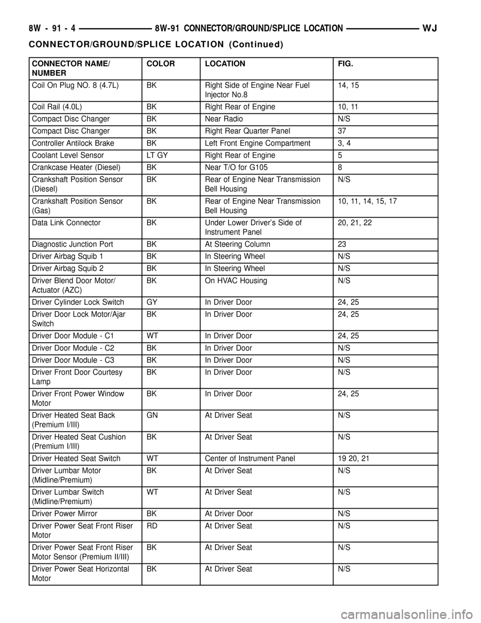
CONNECTOR NAME/
NUMBERCOLOR LOCATION FIG.
Coil On Plug NO. 8 (4.7L) BK Right Side of Engine Near Fuel
Injector No.814, 15
Coil Rail (4.0L) BK Right Rear of Engine 10, 11
Compact Disc Changer BK Near Radio N/S
Compact Disc Changer BK Right Rear Quarter Panel 37
Controller Antilock Brake BK Left Front Engine Compartment 3, 4
Coolant Level Sensor LT GY Right Rear of Engine 5
Crankcase Heater (Diesel) BK Near T/O for G105 8
Crankshaft Position Sensor
(Diesel)BK Rear of Engine Near Transmission
Bell HousingN/S
Crankshaft Position Sensor
(Gas)BK Rear of Engine Near Transmission
Bell Housing10, 11, 14, 15, 17
Data Link Connector BK Under Lower Driver's Side of
Instrument Panel20, 21, 22
Diagnostic Junction Port BK At Steering Column 23
Driver Airbag Squib 1 BK In Steering Wheel N/S
Driver Airbag Squib 2 BK In Steering Wheel N/S
Driver Blend Door Motor/
Actuator (AZC)BK On HVAC Housing N/S
Driver Cylinder Lock Switch GY In Driver Door 24, 25
Driver Door Lock Motor/Ajar
SwitchBK In Driver Door 24, 25
Driver Door Module - C1 WT In Driver Door 24, 25
Driver Door Module - C2 BK In Driver Door N/S
Driver Door Module - C3 BK In Driver Door N/S
Driver Front Door Courtesy
LampBK In Driver Door N/S
Driver Front Power Window
MotorBK In Driver Door 24, 25
Driver Heated Seat Back
(Premium I/III)GN At Driver Seat N/S
Driver Heated Seat Cushion
(Premium I/III)BK At Driver Seat N/S
Driver Heated Seat Switch WT Center of Instrument Panel 19 20, 21
Driver Lumbar Motor
(Midline/Premium)BK At Driver Seat N/S
Driver Lumbar Switch
(Midline/Premium)WT At Driver Seat N/S
Driver Power Mirror BK At Driver Door N/S
Driver Power Seat Front Riser
MotorRD At Driver Seat N/S
Driver Power Seat Front Riser
Motor Sensor (Premium II/III)BK At Driver Seat N/S
Driver Power Seat Horizontal
MotorBK At Driver Seat N/S
8W - 91 - 4 8W-91 CONNECTOR/GROUND/SPLICE LOCATIONWJ
CONNECTOR/GROUND/SPLICE LOCATION (Continued)
Page 1181 of 2199
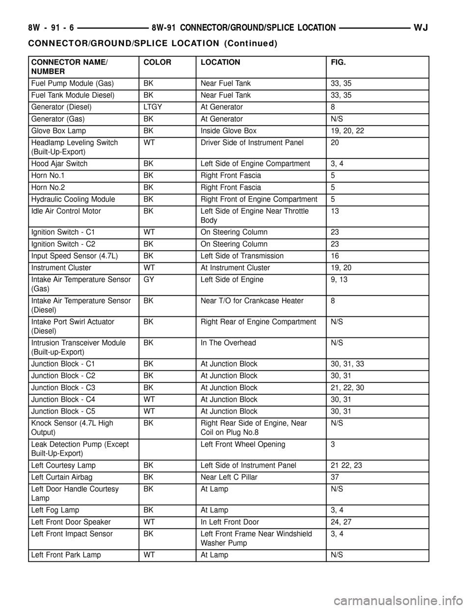
CONNECTOR NAME/
NUMBERCOLOR LOCATION FIG.
Fuel Pump Module (Gas) BK Near Fuel Tank 33, 35
Fuel Tank Module Diesel) BK Near Fuel Tank 33, 35
Generator (Diesel) LTGY At Generator 8
Generator (Gas) BK At Generator N/S
Glove Box Lamp BK Inside Glove Box 19, 20, 22
Headlamp Leveling Switch
(Built-Up-Export)WT Driver Side of Instrument Panel 20
Hood Ajar Switch BK Left Side of Engine Compartment 3, 4
Horn No.1 BK Right Front Fascia 5
Horn No.2 BK Right Front Fascia 5
Hydraulic Cooling Module BK Right Front of Engine Compartment 5
Idle Air Control Motor BK Left Side of Engine Near Throttle
Body13
Ignition Switch - C1 WT On Steering Column 23
Ignition Switch - C2 BK On Steering Column 23
Input Speed Sensor (4.7L) BK Left Side of Transmission 16
Instrument Cluster WT At Instrument Cluster 19, 20
Intake Air Temperature Sensor
(Gas)GY Left Side of Engine 9, 13
Intake Air Temperature Sensor
(Diesel)BK Near T/O for Crankcase Heater 8
Intake Port Swirl Actuator
(Diesel)BK Right Rear of Engine Compartment N/S
Intrusion Transceiver Module
(Built-up-Export)BK In The Overhead N/S
Junction Block - C1 BK At Junction Block 30, 31, 33
Junction Block - C2 BK At Junction Block 30, 31
Junction Block - C3 BK At Junction Block 21, 22, 30
Junction Block - C4 WT At Junction Block 30, 31
Junction Block - C5 WT At Junction Block 30, 31
Knock Sensor (4.7L High
Output)BK Right Rear Side of Engine, Near
Coil on Plug No.8N/S
Leak Detection Pump (Except
Built-Up-Export)Left Front Wheel Opening 3
Left Courtesy Lamp BK Left Side of Instrument Panel 21 22, 23
Left Curtain Airbag BK Near Left C Pillar 37
Left Door Handle Courtesy
LampBK At Lamp N/S
Left Fog Lamp BK At Lamp 3, 4
Left Front Door Speaker WT In Left Front Door 24, 27
Left Front Impact Sensor BK Left Front Frame Near Windshield
Washer Pump3, 4
Left Front Park Lamp WT At Lamp N/S
8W - 91 - 6 8W-91 CONNECTOR/GROUND/SPLICE LOCATIONWJ
CONNECTOR/GROUND/SPLICE LOCATION (Continued)
Page 1182 of 2199
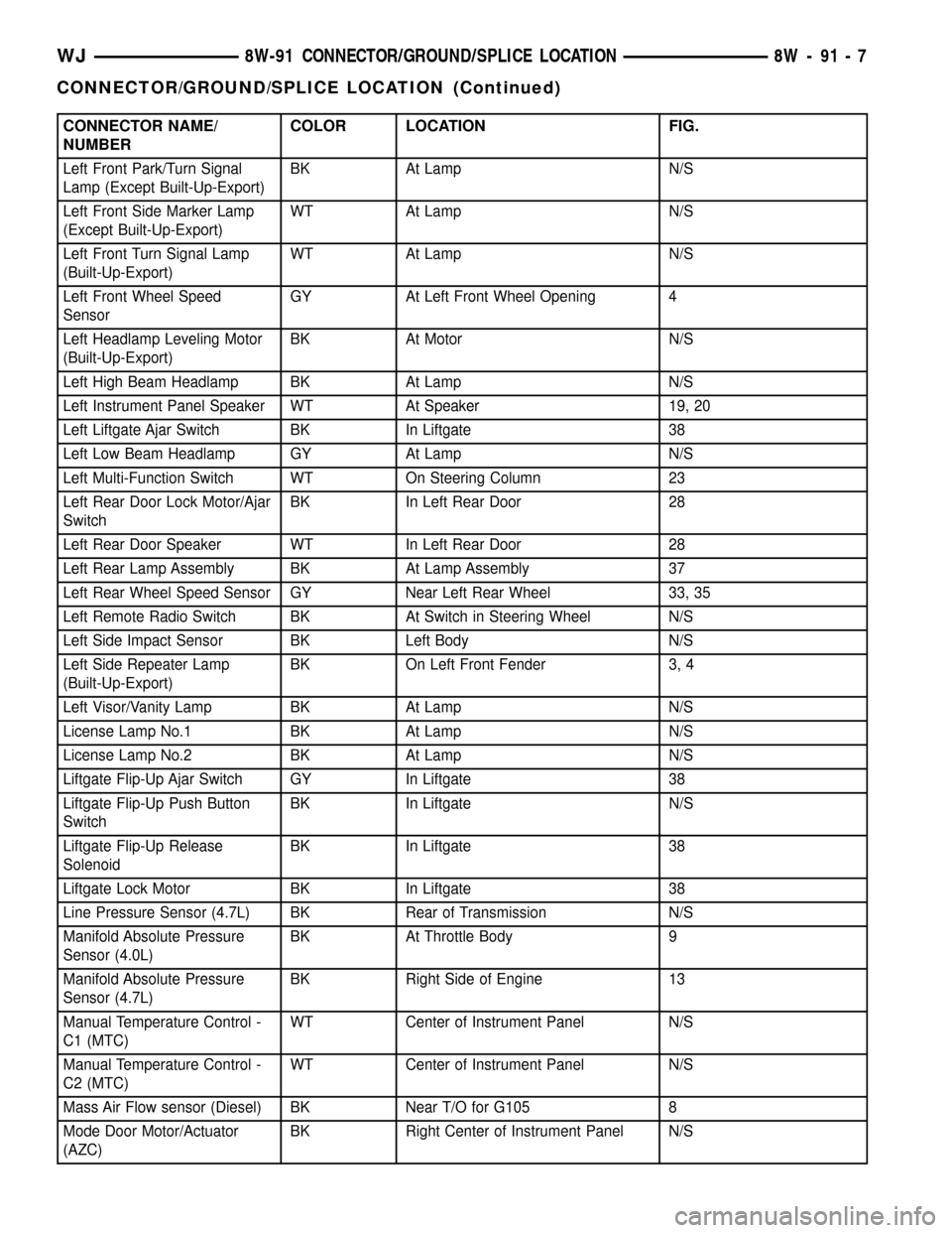
CONNECTOR NAME/
NUMBERCOLOR LOCATION FIG.
Left Front Park/Turn Signal
Lamp (Except Built-Up-Export)BK At Lamp N/S
Left Front Side Marker Lamp
(Except Built-Up-Export)WT At Lamp N/S
Left Front Turn Signal Lamp
(Built-Up-Export)WT At Lamp N/S
Left Front Wheel Speed
SensorGY At Left Front Wheel Opening 4
Left Headlamp Leveling Motor
(Built-Up-Export)BK At Motor N/S
Left High Beam Headlamp BK At Lamp N/S
Left Instrument Panel Speaker WT At Speaker 19, 20
Left Liftgate Ajar Switch BK In Liftgate 38
Left Low Beam Headlamp GY At Lamp N/S
Left Multi-Function Switch WT On Steering Column 23
Left Rear Door Lock Motor/Ajar
SwitchBK In Left Rear Door 28
Left Rear Door Speaker WT In Left Rear Door 28
Left Rear Lamp Assembly BK At Lamp Assembly 37
Left Rear Wheel Speed Sensor GY Near Left Rear Wheel 33, 35
Left Remote Radio Switch BK At Switch in Steering Wheel N/S
Left Side Impact Sensor BK Left Body N/S
Left Side Repeater Lamp
(Built-Up-Export)BK On Left Front Fender 3, 4
Left Visor/Vanity Lamp BK At Lamp N/S
License Lamp No.1 BK At Lamp N/S
License Lamp No.2 BK At Lamp N/S
Liftgate Flip-Up Ajar Switch GY In Liftgate 38
Liftgate Flip-Up Push Button
SwitchBK In Liftgate N/S
Liftgate Flip-Up Release
SolenoidBK In Liftgate 38
Liftgate Lock Motor BK In Liftgate 38
Line Pressure Sensor (4.7L) BK Rear of Transmission N/S
Manifold Absolute Pressure
Sensor (4.0L)BK At Throttle Body 9
Manifold Absolute Pressure
Sensor (4.7L)BK Right Side of Engine 13
Manual Temperature Control -
C1 (MTC)WT Center of Instrument Panel N/S
Manual Temperature Control -
C2 (MTC)WT Center of Instrument Panel N/S
Mass Air Flow sensor (Diesel) BK Near T/O for G105 8
Mode Door Motor/Actuator
(AZC)BK Right Center of Instrument Panel N/S
WJ8W-91 CONNECTOR/GROUND/SPLICE LOCATION 8W - 91 - 7
CONNECTOR/GROUND/SPLICE LOCATION (Continued)
Page 1183 of 2199
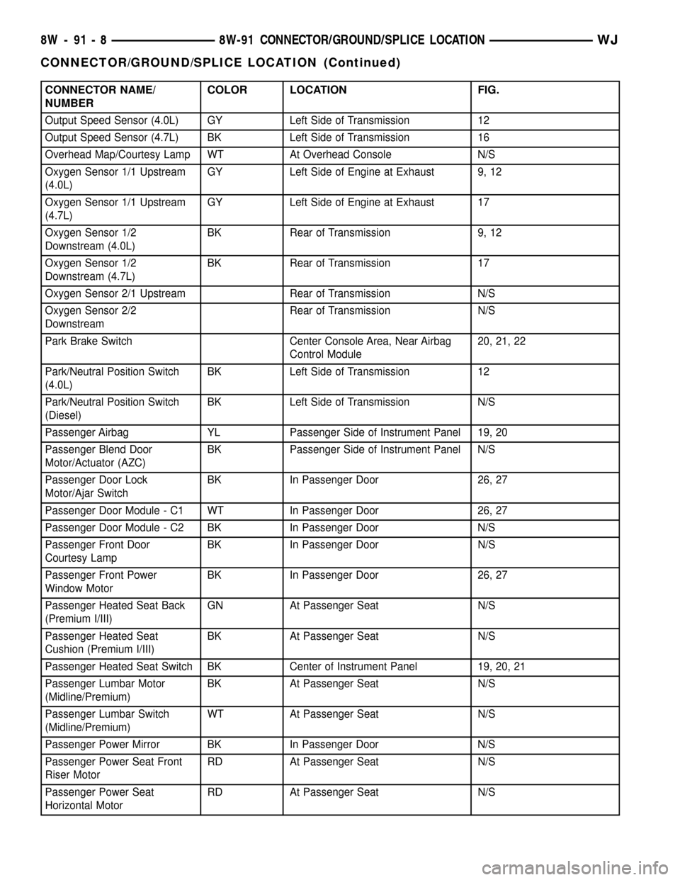
CONNECTOR NAME/
NUMBERCOLOR LOCATION FIG.
Output Speed Sensor (4.0L) GY Left Side of Transmission 12
Output Speed Sensor (4.7L) BK Left Side of Transmission 16
Overhead Map/Courtesy Lamp WT At Overhead Console N/S
Oxygen Sensor 1/1 Upstream
(4.0L)GY Left Side of Engine at Exhaust 9, 12
Oxygen Sensor 1/1 Upstream
(4.7L)GY Left Side of Engine at Exhaust 17
Oxygen Sensor 1/2
Downstream (4.0L)BK Rear of Transmission 9, 12
Oxygen Sensor 1/2
Downstream (4.7L)BK Rear of Transmission 17
Oxygen Sensor 2/1 Upstream Rear of Transmission N/S
Oxygen Sensor 2/2
DownstreamRear of Transmission N/S
Park Brake Switch Center Console Area, Near Airbag
Control Module20, 21, 22
Park/Neutral Position Switch
(4.0L)BK Left Side of Transmission 12
Park/Neutral Position Switch
(Diesel)BK Left Side of Transmission N/S
Passenger Airbag YL Passenger Side of Instrument Panel 19, 20
Passenger Blend Door
Motor/Actuator (AZC)BK Passenger Side of Instrument Panel N/S
Passenger Door Lock
Motor/Ajar SwitchBK In Passenger Door 26, 27
Passenger Door Module - C1 WT In Passenger Door 26, 27
Passenger Door Module - C2 BK In Passenger Door N/S
Passenger Front Door
Courtesy LampBK In Passenger Door N/S
Passenger Front Power
Window MotorBK In Passenger Door 26, 27
Passenger Heated Seat Back
(Premium I/III)GN At Passenger Seat N/S
Passenger Heated Seat
Cushion (Premium I/III)BK At Passenger Seat N/S
Passenger Heated Seat Switch BK Center of Instrument Panel 19, 20, 21
Passenger Lumbar Motor
(Midline/Premium)BK At Passenger Seat N/S
Passenger Lumbar Switch
(Midline/Premium)WT At Passenger Seat N/S
Passenger Power Mirror BK In Passenger Door N/S
Passenger Power Seat Front
Riser MotorRD At Passenger Seat N/S
Passenger Power Seat
Horizontal MotorRD At Passenger Seat N/S
8W - 91 - 8 8W-91 CONNECTOR/GROUND/SPLICE LOCATIONWJ
CONNECTOR/GROUND/SPLICE LOCATION (Continued)
Page 1186 of 2199
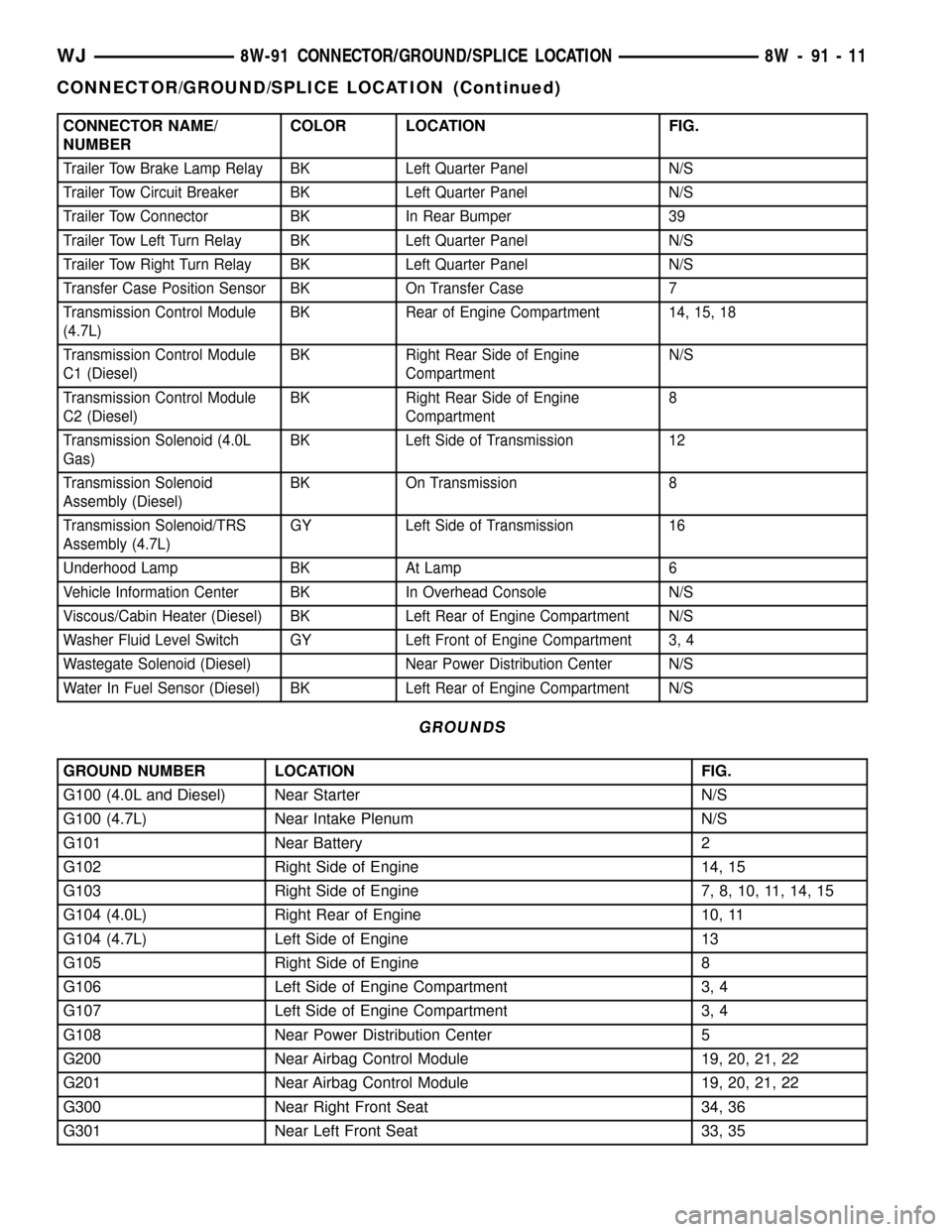
CONNECTOR NAME/
NUMBERCOLOR LOCATION FIG.
Trailer Tow Brake Lamp Relay BK Left Quarter Panel N/S
Trailer Tow Circuit Breaker BK Left Quarter Panel N/S
Trailer Tow Connector BK In Rear Bumper 39
Trailer Tow Left Turn Relay BK Left Quarter Panel N/S
Trailer Tow Right Turn Relay BK Left Quarter Panel N/S
Transfer Case Position Sensor BK On Transfer Case 7
Transmission Control Module
(4.7L)BK Rear of Engine Compartment 14, 15, 18
Transmission Control Module
C1 (Diesel)BK Right Rear Side of Engine
CompartmentN/S
Transmission Control Module
C2 (Diesel)BK Right Rear Side of Engine
Compartment8
Transmission Solenoid (4.0L
Gas)BK Left Side of Transmission 12
Transmission Solenoid
Assembly (Diesel)BK On Transmission 8
Transmission Solenoid/TRS
Assembly (4.7L)GY Left Side of Transmission 16
Underhood Lamp BK At Lamp 6
Vehicle Information Center BK In Overhead Console N/S
Viscous/Cabin Heater (Diesel) BK Left Rear of Engine Compartment N/S
Washer Fluid Level Switch GY Left Front of Engine Compartment 3, 4
Wastegate Solenoid (Diesel) Near Power Distribution Center N/S
Water In Fuel Sensor (Diesel) BK Left Rear of Engine Compartment N/S
GROUNDS
GROUND NUMBER LOCATION FIG.
G100 (4.0L and Diesel) Near Starter N/S
G100 (4.7L) Near Intake Plenum N/S
G101 Near Battery 2
G102 Right Side of Engine 14, 15
G103 Right Side of Engine 7, 8, 10, 11, 14, 15
G104 (4.0L) Right Rear of Engine 10, 11
G104 (4.7L) Left Side of Engine 13
G105 Right Side of Engine 8
G106 Left Side of Engine Compartment 3, 4
G107 Left Side of Engine Compartment 3, 4
G108 Near Power Distribution Center 5
G200 Near Airbag Control Module 19, 20, 21, 22
G201 Near Airbag Control Module 19, 20, 21, 22
G300 Near Right Front Seat 34, 36
G301 Near Left Front Seat 33, 35
WJ8W-91 CONNECTOR/GROUND/SPLICE LOCATION 8W - 91 - 11
CONNECTOR/GROUND/SPLICE LOCATION (Continued)
Page 1254 of 2199
CAUTION: DO NOT use engine or transmission oil,
mineral spirits, or kerosene.
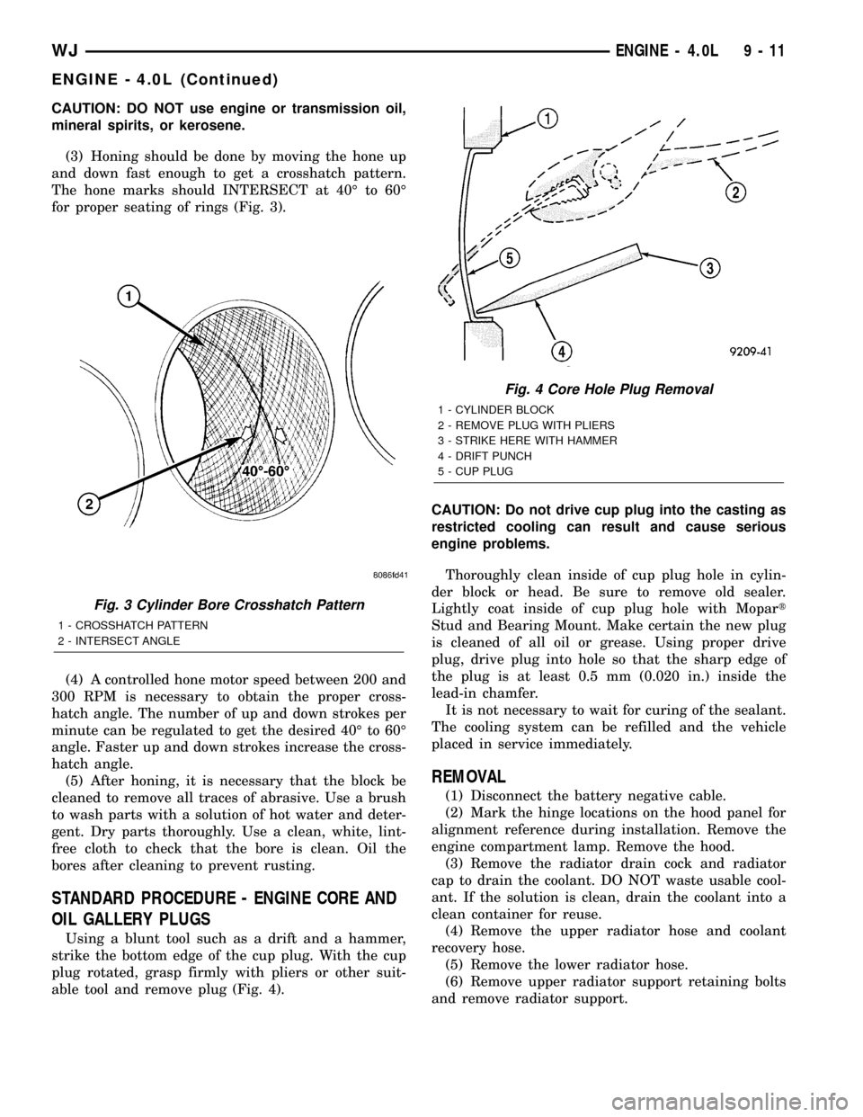
(3) Honing should be done by moving the hone up
and down fast enough to get a crosshatch pattern.
The hone marks should INTERSECT at 40É to 60É
for proper seating of rings (Fig. 3).
(4) A controlled hone motor speed between 200 and
300 RPM is necessary to obtain the proper cross-
hatch angle. The number of up and down strokes per
minute can be regulated to get the desired 40É to 60É
angle. Faster up and down strokes increase the cross-
hatch angle.
(5) After honing, it is necessary that the block be
cleaned to remove all traces of abrasive. Use a brush
to wash parts with a solution of hot water and deter-
gent. Dry parts thoroughly. Use a clean, white, lint-
free cloth to check that the bore is clean. Oil the
bores after cleaning to prevent rusting.
STANDARD PROCEDURE - ENGINE CORE AND
OIL GALLERY PLUGS
Using a blunt tool such as a drift and a hammer,
strike the bottom edge of the cup plug. With the cup
plug rotated, grasp firmly with pliers or other suit-
able tool and remove plug (Fig. 4).CAUTION: Do not drive cup plug into the casting as
restricted cooling can result and cause serious
engine problems.
Thoroughly clean inside of cup plug hole in cylin-
der block or head. Be sure to remove old sealer.
Lightly coat inside of cup plug hole with Mopart
Stud and Bearing Mount. Make certain the new plug
is cleaned of all oil or grease. Using proper drive
plug, drive plug into hole so that the sharp edge of
the plug is at least 0.5 mm (0.020 in.) inside the
lead-in chamfer.
It is not necessary to wait for curing of the sealant.
The cooling system can be refilled and the vehicle
placed in service immediately.
REMOVAL
(1) Disconnect the battery negative cable.
(2) Mark the hinge locations on the hood panel for
alignment reference during installation. Remove the
engine compartment lamp. Remove the hood.
(3) Remove the radiator drain cock and radiator
cap to drain the coolant. DO NOT waste usable cool-
ant. If the solution is clean, drain the coolant into a
clean container for reuse.
(4) Remove the upper radiator hose and coolant
recovery hose.
(5) Remove the lower radiator hose.
(6) Remove upper radiator support retaining bolts
and remove radiator support.
Fig. 3 Cylinder Bore Crosshatch Pattern
1 - CROSSHATCH PATTERN
2 - INTERSECT ANGLE
Fig. 4 Core Hole Plug Removal
1 - CYLINDER BLOCK
2 - REMOVE PLUG WITH PLIERS
3 - STRIKE HERE WITH HAMMER
4 - DRIFT PUNCH
5 - CUP PLUG
WJENGINE - 4.0L 9 - 11
ENGINE - 4.0L (Continued)