Power JEEP GRAND CHEROKEE 2002 WJ / 2.G Workshop Manual
[x] Cancel search | Manufacturer: JEEP, Model Year: 2002, Model line: GRAND CHEROKEE, Model: JEEP GRAND CHEROKEE 2002 WJ / 2.GPages: 2199, PDF Size: 76.01 MB
Page 2153 of 2199

VISCOUS HEATER
DESCRIPTION
DESCRIPTION
The diesel engine has an engine mounted mechan-
ical device called a Viscous Heater that is used to
heat the coolant coming from the engine to the
heater core. The Viscous Heater is driven by the
engine fan belt and has a electro-mechanical clutch
which is controlled by the HVAC control unit.
DESCRIPTION - VISCOUS HEATER CLUTCH
The basic viscous heater clutch assembly consists
of a stationary electromagnetic coil, a hub bearing
and pulley assembly and a clutch plate. The electro-
magnetic coil unit and the hub bearing and pulley
assembly are each retained on the nose of the com-
pressor front housing with snap rings (Fig. 17). The
clutch plate is keyed to the viscous heater shaft and
secured with a nut. These components provide the
means to engage and disengage the viscous heater
from the engine accessory drive belt.
OPERATION
OPERATION - VISCOUS HEATER
The Viscous Heater is driven by the engine fan
belt. The Viscous Heater has an electro-mechanical
clutch that receives a signal from the HVAC control
head and the Viscous Heater controller that ener-
gizes and engages the clutch. Once engaged theclutch allows the Viscous Heater to increase the tem-
perature of the coolant flowing to the heater core,
which provides heat the passenger compartment
quicker than normal engines without the Viscous
Heater. The Viscous Heater generates heat by means
of friction which heats a special Silicon Oil within its
housing which is then transferred to the engine cool-
ant when the coolant passes over fins within the
pump. Please note that the coolant is isolated from
the silicon oil within the pump housing. When
demand for passenger compartment heat decreases
the Viscous Heater clutch will receive an input from
the Viscous heater controller to disengage.
OPERATION - VISCOUS HEATER CLUTCH
When the clutch coil is energized, it magnetically
draws the clutch into contact with the pulley and
drives the viscous heater shaft. When the coil is not
energized the pulley freewheels on the clutch hub
bearing, which is part of the pulley. The viscous
heater clutch and coil are the only serviced parts on
the viscous heater assembly. If the viscous heater is
inoperative or damaged the entire assembly must be
replaced. The viscous heater clutch engagement is
controlled by several components: the viscous heater
controller, the engine powertrain control module and
the HVAC control head.
REMOVAL
REMOVAL - VISCOUS HEATER
(1) Drain the engine coolant(Refer to 7 - COOL-
ING/ENGINE - STANDARD PROCEDURE).
(2) Remove the engine accessory drive belt(Refer to
7 - COOLING/ACCESSORY DRIVE/DRIVE BELTS -
REMOVAL).
(3) Remove the heater hose clamps at the Viscous
Heater.
(4) Remove the heater hoses from the Viscous
Heater.
(5) Unplug the Viscous Heater clutch electrical
connector.
(6) Remove the bolts holding the Viscous Heater to
the mounting bracket.
(7) Remove the Viscous Heater from the vehicle.
REMOVAL - VISCOUS HEATER CLUTCH
(1) The viscous heater clutch can be serviced in
the vehicle and the cooling system does not have to
be drained.
(2) Disconnect and isolate the battery negative
cable.
(3) Remove the serpentine drive belt(Refer to 7 -
COOLING/ACCESSORY DRIVE/DRIVE BELTS -
REMOVAL).
Fig. 17 CLUTCH ASSEMBLY- typical
1 - CLUTCH PLATE
2 - SHAFT KEY
3 - PULLEY
4 - COIL
5 - CLUTCH SHIMS
6 - SNAP RING
7 - SNAP RING
24 - 76 PLUMBINGWJ
Page 2156 of 2199

EMISSIONS CONTROL
TABLE OF CONTENTS
page page
EMISSIONS CONTROL
DESCRIPTION
DESCRIPTION - EMISSION CONTROL
SYSTEM.............................1
DESCRIPTION - STATE DISPLAY TEST
MODE...............................2
DESCRIPTION - CIRCUIT ACTUATION TEST
MODE...............................2
DESCRIPTION - DIAGNOSTIC TROUBLE
CODES..............................2DESCRIPTION - TASK MANAGER.........17
DESCRIPTION - MONITORED SYSTEMS . . . 17
DESCRIPTION - TRIP DEFINITION........19
DESCRIPTION - COMPONENT MONITORS . . 19
DESCRIPTION - NON-MONITORED
CIRCUITS...........................20
DESCRIPTION - HIGH AND LOW LIMITS . . . 20
DESCRIPTION - LOAD VALUE...........20
OPERATION - TASK MANAGER............21
EVAPORATIVE EMISSIONS................24
EMISSIONS CONTROL
DESCRIPTION
DESCRIPTION - EMISSION CONTROL SYSTEM
The Powertrain Control Module (PCM) monitors
many different circuits in the fuel injection, ignition,
emission and engine systems. If the PCM senses a prob-
lem with a monitored circuit often enough to indicate an
actual problem, it stores a Diagnostic Trouble Code
(DTC) in the PCM's memory. If the code applies to a
non-emissions related component or system, and the
problem is repaired or ceases to exist, the PCM cancels
the code after 40 warm-up cycles. Diagnostic trouble
codes that affect vehicle emissions illuminate the Mal-
function Indicator (check engine) Lamp. Refer to Mal-
function Indicator Lamp in this section.
Certain criteria must be met before the PCM
stores a DTC in memory. The criteria may be a spe-
cific range of engine RPM, engine temperature,
and/or input voltage to the PCM.
The PCM might not store a DTC for a monitored cir-
cuit even though a malfunction has occurred. This may
happen because one of the DTC criteria for the circuit
has not been met.For example
,assume the diagnostic
trouble code criteria requires the PCM to monitor the
circuit only when the engine operates between 750 and
2000 RPM. Suppose the sensor's output circuit shorts to
ground when engine operates above 2400 RPM (result-
ing in 0 volt input to the PCM). Because the condition
happens at an engine speed above the maximum thresh-
old (2000 rpm), the PCM will not store a DTC.
There are several operating conditions for which
the PCM monitors and sets DTC's. Refer to Moni-
tored Systems, Components, and Non-Monitored Cir-
cuits in this section.Technicians must retrieve stored DTC's by connect-
ing the DRB scan tool (or an equivalent scan tool) to
the 16±way data link connector (Fig. 1).
NOTE: Various diagnostic procedures may actually
cause a diagnostic monitor to set a DTC. For
instance, pulling a spark plug wire to perform a
spark test may set the misfire code. When a repair
is completed and verified, connect the DRB scan
tool to the 16±way data link connector to erase all
DTC's and extinguish the MIL (check engine lamp).Fig. 1 Data Link (Diagnostic) Connector Location
1 - INSTRUMENT PANEL LOWER/LEFT EDGE
2 - DATA LINK CONNECTOR
WJEMISSIONS CONTROL 25 - 1
Page 2157 of 2199
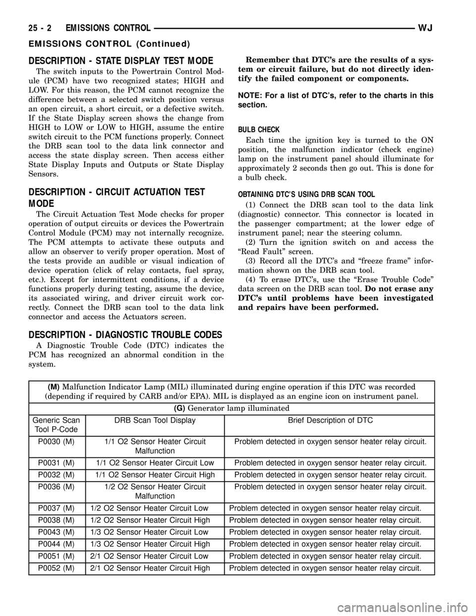
DESCRIPTION - STATE DISPLAY TEST MODE
The switch inputs to the Powertrain Control Mod-
ule (PCM) have two recognized states; HIGH and
LOW. For this reason, the PCM cannot recognize the
difference between a selected switch position versus
an open circuit, a short circuit, or a defective switch.
If the State Display screen shows the change from
HIGH to LOW or LOW to HIGH, assume the entire
switch circuit to the PCM functions properly. Connect
the DRB scan tool to the data link connector and
access the state display screen. Then access either
State Display Inputs and Outputs or State Display
Sensors.
DESCRIPTION - CIRCUIT ACTUATION TEST
MODE
The Circuit Actuation Test Mode checks for proper
operation of output circuits or devices the Powertrain
Control Module (PCM) may not internally recognize.
The PCM attempts to activate these outputs and
allow an observer to verify proper operation. Most of
the tests provide an audible or visual indication of
device operation (click of relay contacts, fuel spray,
etc.). Except for intermittent conditions, if a device
functions properly during testing, assume the device,
its associated wiring, and driver circuit work cor-
rectly. Connect the DRB scan tool to the data link
connector and access the Actuators screen.
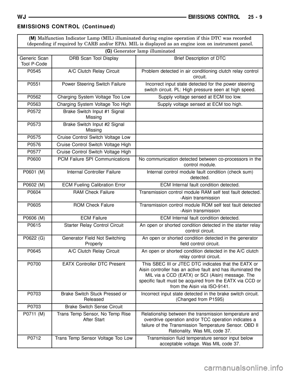
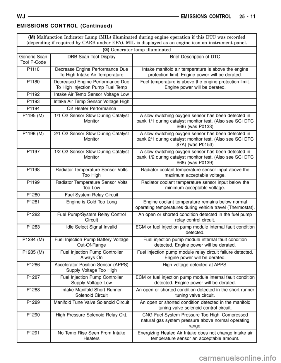
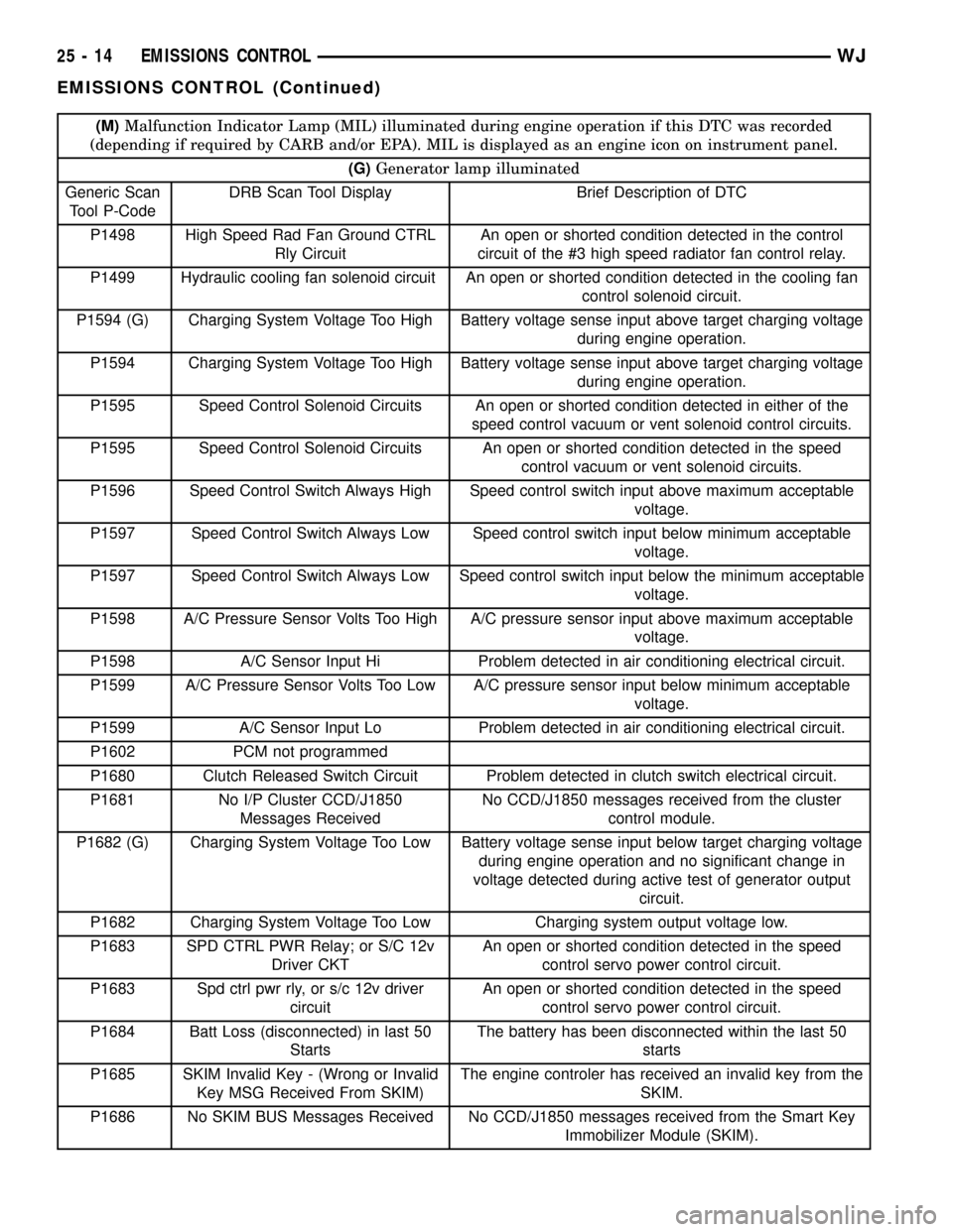
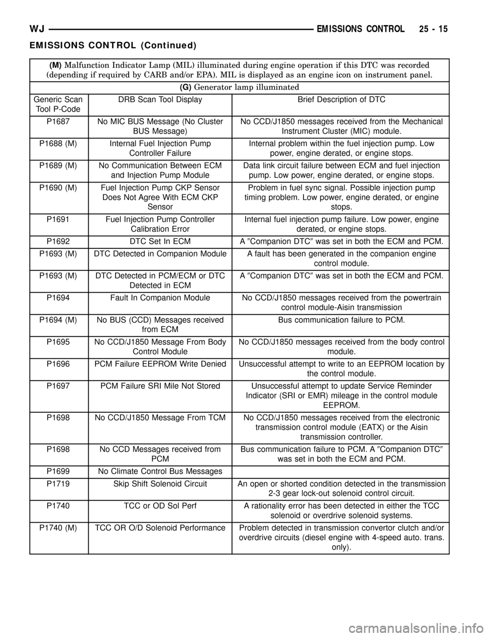
DESCRIPTION - DIAGNOSTIC TROUBLE CODES
A Diagnostic Trouble Code (DTC) indicates the
PCM has recognized an abnormal condition in the
system.Remember that DTC's are the results of a sys-
tem or circuit failure, but do not directly iden-
tify the failed component or components.
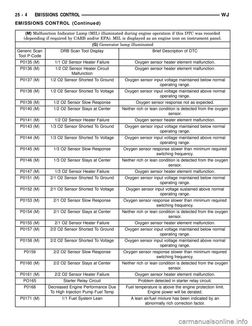
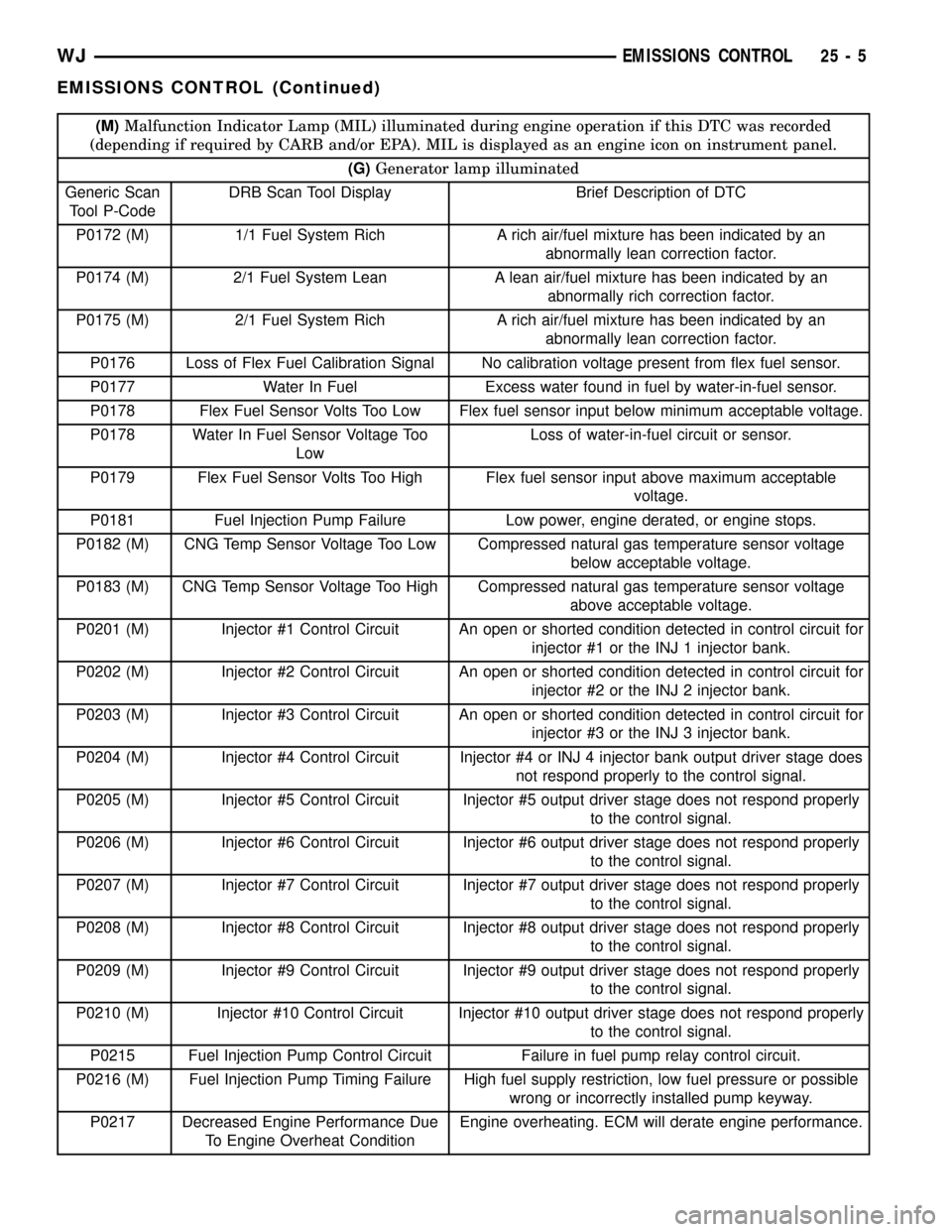
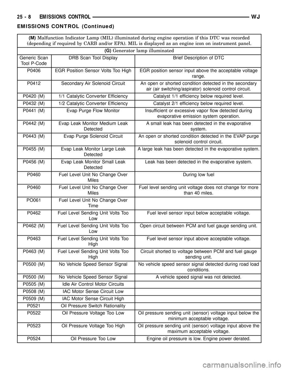
NOTE: For a list of DTC's, refer to the charts in this
section.
BULB CHECK
Each time the ignition key is turned to the ON
position, the malfunction indicator (check engine)
lamp on the instrument panel should illuminate for
approximately 2 seconds then go out. This is done for
a bulb check.
OBTAINING DTC'S USING DRB SCAN TOOL
(1) Connect the DRB scan tool to the data link
(diagnostic) connector. This connector is located in
the passenger compartment; at the lower edge of
instrument panel; near the steering column.
(2) Turn the ignition switch on and access the
ªRead Faultº screen.
(3) Record all the DTC's and ªfreeze frameº infor-
mation shown on the DRB scan tool.
(4) To erase DTC's, use the ªErase Trouble Codeº
data screen on the DRB scan tool.Do not erase any
DTC's until problems have been investigated
and repairs have been performed.
(M)Malfunction Indicator Lamp (MIL) illuminated during engine operation if this DTC was recorded
(depending if required by CARB and/or EPA). MIL is displayed as an engine icon on instrument panel.
(G)Generator lamp illuminated
Generic Scan
Tool P-CodeDRB Scan Tool Display Brief Description of DTC
P0030 (M) 1/1 O2 Sensor Heater Circuit
MalfunctionProblem detected in oxygen sensor heater relay circuit.
P0031 (M) 1/1 O2 Sensor Heater Circuit Low Problem detected in oxygen sensor heater relay circuit.
P0032 (M) 1/1 O2 Sensor Heater Circuit High Problem detected in oxygen sensor heater relay circuit.
P0036 (M) 1/2 O2 Sensor Heater Circuit
MalfunctionProblem detected in oxygen sensor heater relay circuit.
P0037 (M) 1/2 O2 Sensor Heater Circuit Low Problem detected in oxygen sensor heater relay circuit.
P0038 (M) 1/2 O2 Sensor Heater Circuit High Problem detected in oxygen sensor heater relay circuit.
P0043 (M) 1/3 O2 Sensor Heater Circuit Low Problem detected in oxygen sensor heater relay circuit.
P0044 (M) 1/3 O2 Sensor Heater Circuit High Problem detected in oxygen sensor heater relay circuit.
P0051 (M) 2/1 O2 Sensor Heater Circuit Low Problem detected in oxygen sensor heater relay circuit.
P0052 (M) 2/1 O2 Sensor Heater Circuit High Problem detected in oxygen sensor heater relay circuit.
25 - 2 EMISSIONS CONTROLWJ
EMISSIONS CONTROL (Continued)
Page 2159 of 2199
(M)Malfunction Indicator Lamp (MIL) illuminated during engine operation if this DTC was recorded
(depending if required by CARB and/or EPA). MIL is displayed as an engine icon on instrument panel.
(G)Generator lamp illuminated
Generic Scan
Tool P-CodeDRB Scan Tool Display Brief Description of DTC
P0135 (M) 1/1 O2 Sensor Heater Failure Oxygen sensor heater element malfunction.
P0136 (M) 1/2 O2 Sensor Heater Circuit
MalfunctionOxygen sensor heater element malfunction.
P0137 (M) 1/2 O2 Sensor Shorted To Ground Oxygen sensor input voltage maintained below normal
operating range.
P0138 (M) 1/2 O2 Sensor Shorted To Voltage Oxygen sensor input voltage maintained above normal
operating range.
P0139 (M) 1/2 O2 Sensor Slow Response Oxygen sensor response not as expected.
P0140 (M) 1/2 O2 Sensor Stays at Center Neither rich or lean condition is detected from the oxygen
sensor.
P0141 (M) 1/2 O2 Sensor Heater Failure Oxygen sensor heater element malfunction.
P0143 (M) 1/3 O2 Sensor Shorted To Ground Oxygen sensor input voltage maintained below normal
operating range.
P0144 (M) 1/3 O2 Sensor Shorted To Voltage Oxygen sensor input voltage maintained above normal
operating range.
P0145 (M) 1/3 O2 Sensor Slow Response Oxygen sensor response slower than minimum required
switching frequency.
P0146 (M) 1/3 O2 Sensor Stays at Center Neither rich or lean condition is detected from the oxygen
sensor.
P0147 (M) 1/3 O2 Sensor Heater Failure Oxygen sensor heater element malfunction.
P0151 (M) 2/1 O2 Sensor Shorted To Ground Oxygen sensor input voltage maintained below normal
operating range.
P0152 (M) 2/1 O2 Sensor Shorted To Voltage Oxygen sensor input voltage sustained above normal
operating range.
P0153 (M) 2/1 O2 Sensor Slow Response Oxygen sensor response slower than minimum required
switching frequency.
P0154 (M) 2/1 O2 Sensor Stays at Center Neither rich or lean condition is detected from the oxygen
sensor.
P0155 (M) 2/1 O2 Sensor Heater Failure Oxygen sensor heater element malfunction.
P0157 (M) 2/2 O2 Sensor Shorted To Ground Oxygen sensor input voltage maintained below normal
operating range.
P0158 (M) 2/2 O2 Sensor Shorted To Voltage Oxygen sensor input voltage maintained above normal
operating range.
P0159 2/2 O2 Sensor Slow Response Oxygen sensor response slower than minimum required
switching frequency.
P0160 (M) 2/2 O2 Sensor Stays at Center Neither rich or lean condition is detected from the oxygen
sensor.
P0161 (M) 2/2 O2 Sensor Heater Failure Oxygen sensor heater element malfunction.
PO165 Starter Relay Circuit Problem detected in starter relay circuit.
P0168 Decreased Engine Performance Due
To High Injection Pump Fuel TempFuel temperature is above the engine protection limit.
Engine power will be derated.
P0171 (M) 1/1 Fuel System Lean A lean air/fuel mixture has been indicated by an
abnormally rich correction factor.
25 - 4 EMISSIONS CONTROLWJ
EMISSIONS CONTROL (Continued)
Page 2160 of 2199
(M)Malfunction Indicator Lamp (MIL) illuminated during engine operation if this DTC was recorded
(depending if required by CARB and/or EPA). MIL is displayed as an engine icon on instrument panel.
(G)Generator lamp illuminated
Generic Scan
Tool P-CodeDRB Scan Tool Display Brief Description of DTC
P0172 (M) 1/1 Fuel System Rich A rich air/fuel mixture has been indicated by an
abnormally lean correction factor.
P0174 (M) 2/1 Fuel System Lean A lean air/fuel mixture has been indicated by an
abnormally rich correction factor.
P0175 (M) 2/1 Fuel System Rich A rich air/fuel mixture has been indicated by an
abnormally lean correction factor.
P0176 Loss of Flex Fuel Calibration Signal No calibration voltage present from flex fuel sensor.
P0177 Water In Fuel Excess water found in fuel by water-in-fuel sensor.
P0178 Flex Fuel Sensor Volts Too Low Flex fuel sensor input below minimum acceptable voltage.
P0178 Water In Fuel Sensor Voltage Too
LowLoss of water-in-fuel circuit or sensor.
P0179 Flex Fuel Sensor Volts Too High Flex fuel sensor input above maximum acceptable
voltage.
P0181 Fuel Injection Pump Failure Low power, engine derated, or engine stops.
P0182 (M) CNG Temp Sensor Voltage Too Low Compressed natural gas temperature sensor voltage
below acceptable voltage.
P0183 (M) CNG Temp Sensor Voltage Too High Compressed natural gas temperature sensor voltage
above acceptable voltage.
P0201 (M) Injector #1 Control Circuit An open or shorted condition detected in control circuit for
injector #1 or the INJ 1 injector bank.
P0202 (M) Injector #2 Control Circuit An open or shorted condition detected in control circuit for
injector #2 or the INJ 2 injector bank.
P0203 (M) Injector #3 Control Circuit An open or shorted condition detected in control circuit for
injector #3 or the INJ 3 injector bank.
P0204 (M) Injector #4 Control Circuit Injector #4 or INJ 4 injector bank output driver stage does
not respond properly to the control signal.
P0205 (M) Injector #5 Control Circuit Injector #5 output driver stage does not respond properly
to the control signal.
P0206 (M) Injector #6 Control Circuit Injector #6 output driver stage does not respond properly
to the control signal.
P0207 (M) Injector #7 Control Circuit Injector #7 output driver stage does not respond properly
to the control signal.
P0208 (M) Injector #8 Control Circuit Injector #8 output driver stage does not respond properly
to the control signal.
P0209 (M) Injector #9 Control Circuit Injector #9 output driver stage does not respond properly
to the control signal.
P0210 (M) Injector #10 Control Circuit Injector #10 output driver stage does not respond properly
to the control signal.
P0215 Fuel Injection Pump Control Circuit Failure in fuel pump relay control circuit.
P0216 (M) Fuel Injection Pump Timing Failure High fuel supply restriction, low fuel pressure or possible
wrong or incorrectly installed pump keyway.
P0217 Decreased Engine Performance Due
To Engine Overheat ConditionEngine overheating. ECM will derate engine performance.
WJEMISSIONS CONTROL 25 - 5
EMISSIONS CONTROL (Continued)
Page 2163 of 2199
(M)Malfunction Indicator Lamp (MIL) illuminated during engine operation if this DTC was recorded
(depending if required by CARB and/or EPA). MIL is displayed as an engine icon on instrument panel.
(G)Generator lamp illuminated
Generic Scan
Tool P-CodeDRB Scan Tool Display Brief Description of DTC
P0406 EGR Position Sensor Volts Too High EGR position sensor input above the acceptable voltage
range.
P0412 Secondary Air Solenoid Circuit An open or shorted condition detected in the secondary
air (air switching/aspirator) solenoid control circuit.
P0420 (M) 1/1 Catalytic Converter Efficiency Catalyst 1/1 efficiency below required level.
P0432 (M) 1/2 Catalytic Converter Efficiency Catalyst 2/1 efficiency below required level.
P0441 (M) Evap Purge Flow Monitor Insufficient or excessive vapor flow detected during
evaporative emission system operation.
P0442 (M) Evap Leak Monitor Medium Leak
DetectedA small leak has been detected in the evaporative
system.
P0443 (M) Evap Purge Solenoid Circuit An open or shorted condition detected in the EVAP purge
solenoid control circuit.
P0455 (M) Evap Leak Monitor Large Leak
DetectedA large leak has been detected in the evaporative system.
P0456 (M) Evap Leak Monitor Small Leak
DetectedLeak has been detected in the evaporative system.
P0460 Fuel Level Unit No Change Over
MilesDuring low fuel
P0460 Fuel Level Unit No Change Over
MilesFuel level sending unit voltage does not change for more
than 40 miles.
PO061 Fuel Level Unit No Change Over
Time
P0462 Fuel Level Sending Unit Volts Too
LowFuel level sensor input below acceptable voltage.
P0462 (M) Fuel Level Sending Unit Volts Too
LowOpen circuit between PCM and fuel gauge sending unit.
P0463 Fuel Level Sending Unit Volts Too
HighFuel level sensor input above acceptable voltage.
P0463 (M) Fuel Level Sending Unit Volts Too
HighCircuit shorted to voltage between PCM and fuel gauge
sending unit.
P0500 (M) No Vehicle Speed Sensor Signal No vehicle speed sensor signal detected during road load
conditions.
P0500 (M) No Vehicle Speed Sensor Signal A vehicle speed signal was not detected.
P0505 (M) Idle Air Control Motor Circuits
P0508 (M) IAC Motor Sense Circuit Low
P0509 (M) IAC Motor Sense Circuit High
P0521 Oil Pressure Switch Rationality
P0522 Oil Pressure Voltage Too Low Oil pressure sending unit (sensor) voltage input below the
minimum acceptable voltage.
P0523 Oil Pressure Voltage Too High Oil pressure sending unit (sensor) voltage input above the
maximum acceptable voltage.
P0524 Oil Pressure Too Low Engine oil pressure is low. Engine power derated.
25 - 8 EMISSIONS CONTROLWJ
EMISSIONS CONTROL (Continued)
Page 2164 of 2199
(M)Malfunction Indicator Lamp (MIL) illuminated during engine operation if this DTC was recorded
(depending if required by CARB and/or EPA). MIL is displayed as an engine icon on instrument panel.
(G)Generator lamp illuminated
Generic Scan
Tool P-CodeDRB Scan Tool Display Brief Description of DTC
P0545 A/C Clutch Relay Circuit Problem detected in air conditioning clutch relay control
circuit.
P0551 Power Steering Switch Failure Incorrect input state detected for the power steering
switch circuit. PL: High pressure seen at high speed.
P0562 Charging System Voltage Too Low Supply voltage sensed at ECM too low.
P0563 Charging System Voltage Too High Supply voltage sensed at ECM too high.
P0572 Brake Switch Input #1 Signal
Missing
P0573 Brake Switch Input #2 Signal
Missing
P0575 Cruise Control Switch Voltage Low
P0576 Cruise Control Switch Voltage High
P0577 Cruise Control Switch Voltage High
P0600 PCM Failure SPI Communications No communication detected between co-processors in the
control module.
P0601 (M) Internal Controller Failure Internal control module fault condition (check sum)
detected.
P0602 (M) ECM Fueling Calibration Error ECM Internal fault condition detected.
P0604 RAM Check Failure Transmission control module RAM self test fault detected.
-Aisin transmission
P0605 ROM Check Falure Transmission control module ROM self test fault detected
-Aisin transmission
P0606 (M) ECM Failure ECM Internal fault condition detected.
P0615 Starter Relay Control Circuit An open or shorted condition detected in the starter relay
control circuit.
P0622 (G) Generator Field Not Switching
ProperlyAn open or shorted condition detected in the generator
field control circuit.
P0645 A/C Clutch Relay Circuit An open or shorted condition detected in the A/C clutch
relay control circuit.
P0700 EATX Controller DTC Present This SBEC III or JTEC DTC indicates that the EATX or
Aisin controller has an active fault and has illuminated the
MIL via a CCD (EATX) or SCI (Aisin) message. The
specific fault must be acquired from the EATX via CCD or
from the Aisin via ISO-9141.
P0703 Brake Switch Stuck Pressed or
ReleasedIncorrect input state detected in the brake switch circuit.
(Changed from P1595)
P0703 Brake Switch Sense Circuit
P0711 (M) Trans Temp Sensor, No Temp Rise
After StartRelationship between the transmission temperature and
overdrive operation and/or TCC operation indicates a
failure of the Transmission Temperature Sensor. OBD II
Rationality. Was MIL code 37.
P0712 Trans Temp Sensor Voltage Too Low Transmission fluid temperature sensor input below
acceptable voltage. Was MIL code 37.
WJEMISSIONS CONTROL 25 - 9
EMISSIONS CONTROL (Continued)
Page 2166 of 2199
(M)Malfunction Indicator Lamp (MIL) illuminated during engine operation if this DTC was recorded
(depending if required by CARB and/or EPA). MIL is displayed as an engine icon on instrument panel.
(G)Generator lamp illuminated
Generic Scan
Tool P-CodeDRB Scan Tool Display Brief Description of DTC
P1110 Decrease Engine Performance Due
To High Intake Air TemperatureIntake manifold air temperature is above the engine
protection limit. Engine power will be derated.
P1180 Decreased Engine Performance Due
To High Injection Pump Fuel TempFuel temperature is above the engine protection limit.
Engine power will be derated.
P1192 Intake Air Temp Sensor Voltage Low
P1193 Intake Air Temp Sensor Voltage High
P1194 O2 Heater Performance
P1195 (M) 1/1 O2 Sensor Slow During Catalyst
MonitorA slow switching oxygen sensor has been detected in
bank 1/1 during catalyst monitor test. (Also see SCI DTC
$66) (was P0133)
P1196 (M) 2/1 O2 Sensor Slow During Catalyst
MonitorA slow switching oxygen sensor has been detected in
bank 2/1 during catalyst monitor test. (Also see SCI DTC
$7A) (was P0153)
P1197 1/2 O2 Sensor Slow During Catalyst
MonitorA slow switching oxygen sensor has been detected in
bank 1/2 during catalyst monitor test. (Also see SCI DTC
$68) (was P0139)
P1198 Radiator Temperature Sensor Volts
Too HighRadiator coolant temperature sensor input above the
maximum acceptable voltage.
P1199 Radiator Temperature Sensor Volts
Too LowRadiator coolant temperature sensor input below the
minimum acceptable voltage.
P1280 Fuel System Relay Circuit
P1281 Engine is Cold Too Long Engine coolant temperature remains below normal
operating temperatures during vehicle travel (Thermostat).
P1282 Fuel Pump/System Relay Control
CircuitAn open or shorted condition detected in the fuel pump
relay control circuit.
P1283 Idle Select Signal Invalid ECM or fuel injection pump module internal fault condition
detected.
P1284 (M) Fuel Injection Pump Battery Voltage
Out-Of-RangeFuel injection pump module internal fault condition
detected. Engine power will be derated.
P1285 (M) Fuel Injection Pump Controller
Always OnFuel injection pump module relay circuit failure detected.
Engine power will be derated.
P1286 Accelerator Position Sensor (APPS)
Supply Voltage Too HighHigh voltage detected at APPS.
P1287 Fuel Injection Pump Controller
Supply Voltage LowECM or fuel injection pump module internal fault condition
detected. Engine power will be derated.
P1288 Intake Manifold Short Runner
Solenoid CircuitAn open or shorted condition detected in the short runner
tuning valve circuit.
P1289 Manifold Tune Valve Solenoid Circuit An open or shorted condition detected in the manifold
tuning valve solenoid control circuit.
P1290 High Pressure Solenoid Relay Ckt. CNG Fuel System Pressure Too High±Compressed
natural gas system pressure above normal operating
range.
P1291 No Temp Rise Seen From Intake
HeatersEnergizing Heated Air Intake does not change intake air
temperature sensor an acceptable amount.
WJEMISSIONS CONTROL 25 - 11
EMISSIONS CONTROL (Continued)
Page 2169 of 2199
(M)Malfunction Indicator Lamp (MIL) illuminated during engine operation if this DTC was recorded
(depending if required by CARB and/or EPA). MIL is displayed as an engine icon on instrument panel.
(G)Generator lamp illuminated
Generic Scan
Tool P-CodeDRB Scan Tool Display Brief Description of DTC
P1498 High Speed Rad Fan Ground CTRL
Rly CircuitAn open or shorted condition detected in the control
circuit of the #3 high speed radiator fan control relay.
P1499 Hydraulic cooling fan solenoid circuit An open or shorted condition detected in the cooling fan
control solenoid circuit.
P1594 (G) Charging System Voltage Too High Battery voltage sense input above target charging voltage
during engine operation.
P1594 Charging System Voltage Too High Battery voltage sense input above target charging voltage
during engine operation.
P1595 Speed Control Solenoid Circuits An open or shorted condition detected in either of the
speed control vacuum or vent solenoid control circuits.
P1595 Speed Control Solenoid Circuits An open or shorted condition detected in the speed
control vacuum or vent solenoid circuits.
P1596 Speed Control Switch Always High Speed control switch input above maximum acceptable
voltage.
P1597 Speed Control Switch Always Low Speed control switch input below minimum acceptable
voltage.
P1597 Speed Control Switch Always Low Speed control switch input below the minimum acceptable
voltage.
P1598 A/C Pressure Sensor Volts Too High A/C pressure sensor input above maximum acceptable
voltage.
P1598 A/C Sensor Input Hi Problem detected in air conditioning electrical circuit.
P1599 A/C Pressure Sensor Volts Too Low A/C pressure sensor input below minimum acceptable
voltage.
P1599 A/C Sensor Input Lo Problem detected in air conditioning electrical circuit.
P1602 PCM not programmed
P1680 Clutch Released Switch Circuit Problem detected in clutch switch electrical circuit.
P1681 No I/P Cluster CCD/J1850
Messages ReceivedNo CCD/J1850 messages received from the cluster
control module.
P1682 (G) Charging System Voltage Too Low Battery voltage sense input below target charging voltage
during engine operation and no significant change in
voltage detected during active test of generator output
circuit.
P1682 Charging System Voltage Too Low Charging system output voltage low.
P1683 SPD CTRL PWR Relay; or S/C 12v
Driver CKTAn open or shorted condition detected in the speed
control servo power control circuit.
P1683 Spd ctrl pwr rly, or s/c 12v driver
circuitAn open or shorted condition detected in the speed
control servo power control circuit.
P1684 Batt Loss (disconnected) in last 50
StartsThe battery has been disconnected within the last 50
starts
P1685 SKIM Invalid Key - (Wrong or Invalid
Key MSG Received From SKIM)The engine controler has received an invalid key from the
SKIM.
P1686 No SKIM BUS Messages Received No CCD/J1850 messages received from the Smart Key
Immobilizer Module (SKIM).
25 - 14 EMISSIONS CONTROLWJ
EMISSIONS CONTROL (Continued)
Page 2170 of 2199
(M)Malfunction Indicator Lamp (MIL) illuminated during engine operation if this DTC was recorded
(depending if required by CARB and/or EPA). MIL is displayed as an engine icon on instrument panel.
(G)Generator lamp illuminated
Generic Scan
Tool P-CodeDRB Scan Tool Display Brief Description of DTC
P1687 No MIC BUS Message (No Cluster
BUS Message)No CCD/J1850 messages received from the Mechanical
Instrument Cluster (MIC) module.
P1688 (M) Internal Fuel Injection Pump
Controller FailureInternal problem within the fuel injection pump. Low
power, engine derated, or engine stops.
P1689 (M) No Communication Between ECM
and Injection Pump ModuleData link circuit failure between ECM and fuel injection
pump. Low power, engine derated, or engine stops.
P1690 (M) Fuel Injection Pump CKP Sensor
Does Not Agree With ECM CKP
SensorProblem in fuel sync signal. Possible injection pump
timing problem. Low power, engine derated, or engine
stops.
P1691 Fuel Injection Pump Controller
Calibration ErrorInternal fuel injection pump failure. Low power, engine
derated, or engine stops.
P1692 DTC Set In ECM A9Companion DTC9was set in both the ECM and PCM.
P1693 (M) DTC Detected in Companion Module A fault has been generated in the companion engine
control module.
P1693 (M) DTC Detected in PCM/ECM or DTC
Detected in ECMA9Companion DTC9was set in both the ECM and PCM.
P1694 Fault In Companion Module No CCD/J1850 messages received from the powertrain
control module-Aisin transmission
P1694 (M) No BUS (CCD) Messages received
from ECMBus communication failure to PCM.
P1695 No CCD/J1850 Message From Body
Control ModuleNo CCD/J1850 messages received from the body control
module.
P1696 PCM Failure EEPROM Write Denied Unsuccessful attempt to write to an EEPROM location by
the control module.
P1697 PCM Failure SRI Mile Not Stored Unsuccessful attempt to update Service Reminder
Indicator (SRI or EMR) mileage in the control module
EEPROM.
P1698 No CCD/J1850 Message From TCM No CCD/J1850 messages received from the electronic
transmission control module (EATX) or the Aisin
transmission controller.
P1698 No CCD Messages received from
PCMBus communication failure to PCM. A9Companion DTC9
was set in both the ECM and PCM.
P1699 No Climate Control Bus Messages
P1719 Skip Shift Solenoid Circuit An open or shorted condition detected in the transmission
2-3 gear lock-out solenoid control circuit.
P1740 TCC or OD Sol Perf A rationality error has been detected in either the TCC
solenoid or overdrive solenoid systems.
P1740 (M) TCC OR O/D Solenoid Performance Problem detected in transmission convertor clutch and/or
overdrive circuits (diesel engine with 4-speed auto. trans.
only).
WJEMISSIONS CONTROL 25 - 15
EMISSIONS CONTROL (Continued)