oil JEEP GRAND CHEROKEE 2002 WJ / 2.G Workshop Manual
[x] Cancel search | Manufacturer: JEEP, Model Year: 2002, Model line: GRAND CHEROKEE, Model: JEEP GRAND CHEROKEE 2002 WJ / 2.GPages: 2199, PDF Size: 76.01 MB
Page 1864 of 2199

STANDARD PROCEDURE - TIRE ROTATION
Tires on the front and rear operate at different
loads and perform different steering, driving, and
braking functions. For these reasons they wear at
unequal rates and tend to develop irregular wear
patterns. These effects can be reduced by rotating
the tires at regular intervals. The benefits of tire
rotation are:
²Increase tread life
²Maintain traction levels
²A smooth, quiet ride
The suggested method of tire rotation is (Fig. 10).
Other rotation methods can be used, but they will
not provide all the tire longevity benefits.
STANDARD PROCEDURE - WHEEL
INSTALLATION
The wheel studs and nuts are designed for specific
applications. They must be replaced with equivalent
parts. Do not use replacement parts of lesser quality
or a substitute design. All aluminum and some steel
wheels have wheel stud nuts which feature an
enlarged nose. This enlarged nose is necessary to
ensure proper retention of the aluminum wheels.
NOTE: Do not use chrome plated lug nuts with
chrome plated wheels.
Before installing the wheel, be sure to remove any
build up of corrosion on the wheel mounting surfaces.
Ensure wheels are installed with good metal-to-metal
contact. Improper installation could cause loosening
of wheel nuts. This could affect the safety and han-
dling of your vehicle.
To install the wheel, first position it properly on
the mounting surface. All wheel nuts should then be
tightened just snug. Gradually tighten them in
sequence to the proper torque specification (Fig. 11).
Never use oil or grease on studs or nuts.
Fig. 9 Remount Tire 90 Degrees In Direction of
Arrow
1 - 2ND HIGH SPOT ON TIRE
2 - 1ST HIGH SPOT ON TIRE
Fig. 10 Tire Rotation Pattern
Fig. 11 LUG NUT TIGHTENING PATTERN - TYPICAL
WJTIRES/WHEELS 22 - 5
TIRES/WHEELS (Continued)
Page 1868 of 2199
CLEANING
Remove the protective coating on the tires before
delivery of a vehicle. This coating may cause deteri-
oration of the tires.
To remove the protective coating, apply warm
water and let it soak for a few minutes. Afterwards,
scrub the coating away with a soft bristle brush.
Steam cleaning may also be used to remove the coat-
ing.
NOTE: DO NOT use gasoline, mineral oil, oil-based
solvent or a wire brush for cleaning.
SPECIFICATIONS
TIRES
SPECIFICATIONS
DESCRIPTION SPECIFICATION
TIRE P225/75R16
TIRE P245/70R16
TIRE P235/65R17
SPECIFICATIONS -
SPECIFICATIONS
DESCRIPTION - RIM SPECIFICATION - TIRE
BASE LAREDO (2.7L &
4.0L)
16x7P225/75R16
OPTIONAL LAREDO
(2.7L, 4.0L, 4.7L)
16x7P245/70R16
LAREDO 4.7L (JAPAN &
AUSTRALIA)
17x7.5P235/65R17
OPTIONAL LAREDO (UP
COUNTRY)
17x7.5P235/65R17
BASE LIMITED
17x7.5P235/65R17
OPTIONAL LIMITED (UP
COUNTRY)
& OVERLAND
17x7.5P235/65R17
BASE WHEEL / SNOW
TIREP235/65R17
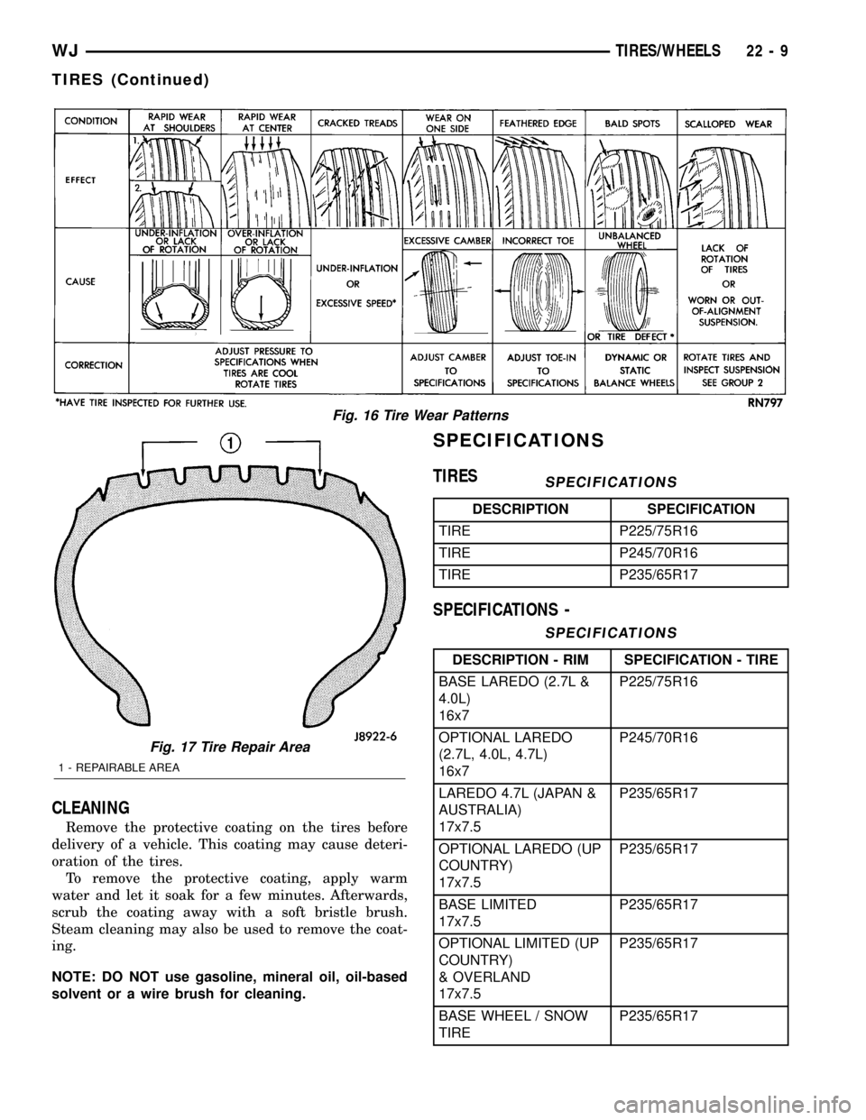
Fig. 16 Tire Wear Patterns
Fig. 17 Tire Repair Area
1 - REPAIRABLE AREA
WJTIRES/WHEELS 22 - 9
TIRES (Continued)
Page 1869 of 2199

SPARE TIRE
DESCRIPTION - SPARE / TEMPORARY TIRE
The temporary spare tire is designed for emer-
gency use only. The original tire should be repaired
or replaced at the first opportunity, then reinstalled.
Do not exceed speeds of 50 M.P.H. when using the
temporary spare tire. Refer to Owner's Manual for
complete details.
WHEELS
DESCRIPTION
The rim size is on the vehicle safety certification
label located on the drivers door shut face. The size
of the rim is determined by the drivetrain package.
Original equipment wheels/rims are designed for
operation up to the specified maximum vehicle capac-
ity.
All models use stamped steel, cast aluminum or
forged aluminum wheels. Every wheel has raised sec-
tions between the rim flanges and rim drop well
called safety humps (Fig. 18) .
Initial inflation of the tire forces the bead over
these raised sections. In case of rapid loss of air pres-
sure, the raised sections help hold the tire on the
wheel.
The wheel studs and nuts are designed for specific
applications. All aluminum and some steel wheels
have wheel stud nuts with an enlarged nose. This
enlarged nose is necessary to ensure proper retentionof the wheels. Do not use replacement studs or nuts
with a different design or lesser quality.
DIAGNOSIS AND TESTING - WHEEL
INSPECTION
Inspect wheels for:
²Excessive run out
²Dents or cracks
²Damaged wheel lug nut holes
²Air Leaks from any area or surface of the rim
NOTE: Do not attempt to repair a wheel by hammer-
ing, heating or welding.
If a wheel is damaged an original equipment
replacement wheel should be used. When obtaining
replacement wheels, they should be equivalent in
load carrying capacity. The diameter, width, offset,
pilot hole and bolt circle of the wheel should be the
same as the original wheel.
WARNING: FAILURE TO USE EQUIVALENT
REPLACEMENT WHEELS MAY ADVERSELY
AFFECT THE SAFETY AND HANDLING OF THE
VEHICLE. USED WHEELS ARE NOT RECOM-
MENDED. THE SERVICE HISTORY OF THE WHEEL
MAY HAVE INCLUDED SEVERE TREATMENT OR
VERY HIGH MILEAGE. THE RIM COULD FAIL WITH-
OUT WARNING.
STANDARD PROCEDURE - WHEEL
REPLACEMENT
The wheel studs and nuts are designed for specific
applications. They must be replaced with equivalent
parts. Do not use replacement parts of lesser quality
or a substitute design. All aluminum and some steel
wheels have wheel stud nuts which feature an
enlarged nose. This enlarged nose is necessary to
ensure proper retention of the aluminum wheels.
NOTE: Do not use chrome plated lug nuts with
chrome plated wheels.
Before installing the wheel, be sure to remove any
build up of corrosion on the wheel mounting surfaces.
Ensure wheels are installed with good metal-to-metal
contact. Improper installation could cause loosening
of wheel nuts. This could affect the safety and han-
dling of your vehicle.
To install the wheel, first position it properly on
the mounting surface. All wheel nuts should then be
tightened just snug. Gradually tighten them in
sequence to the proper torque specification.Never
use oil or grease on studs or nuts.
Wheels must be replaced if they have:
²Excessive runout
Fig. 18 Safety Rim
1 - FLANGE
2 - RIDGE
3 - WELL
22 - 10 TIRES/WHEELSWJ
Page 1876 of 2199
(2) Apply silicone lubricant to a cloth and wipe it
on door seals to avoid over-spray that can soil pas-
senger's clothing.
(3) Before applying lubricant, the component
should be wiped clean. After lubrication, any excess
lubricant should be removed.
(4) The hood latch, latch release mechanism, latch
striker, and safety latch should be lubricated period-
ically.
(5) The door lock cylinders should be lubricated
twice each year (preferably autumn and spring).
(a) Spray a small amount of lock cylinder lubri-
cant directly into the lock cylinder.
(b) Apply a small amount to the key and insert
it into the lock cylinder.
(c) Rotate it to the locked position and then back
to the unlocked position several times.(d) Remove the key. Wipe the lubricant from it
with a clean cloth to avoid soiling of clothing.
STANDARD PROCEDURE - DRILLING AND
WELDING
When holes must be drilled or punched in an inner
body panel, verify depth of space to the outer body
panel, electrical wiring, or other components. Dam-
age to vehicle can result.
Do not weld exterior panels unless combustible
material on the interior of vehicle is removed from
the repair area. Fire or hazardous conditions, can
result.
Always have a fire extinguisher ready for use when
welding.
SPECIFICATIONS
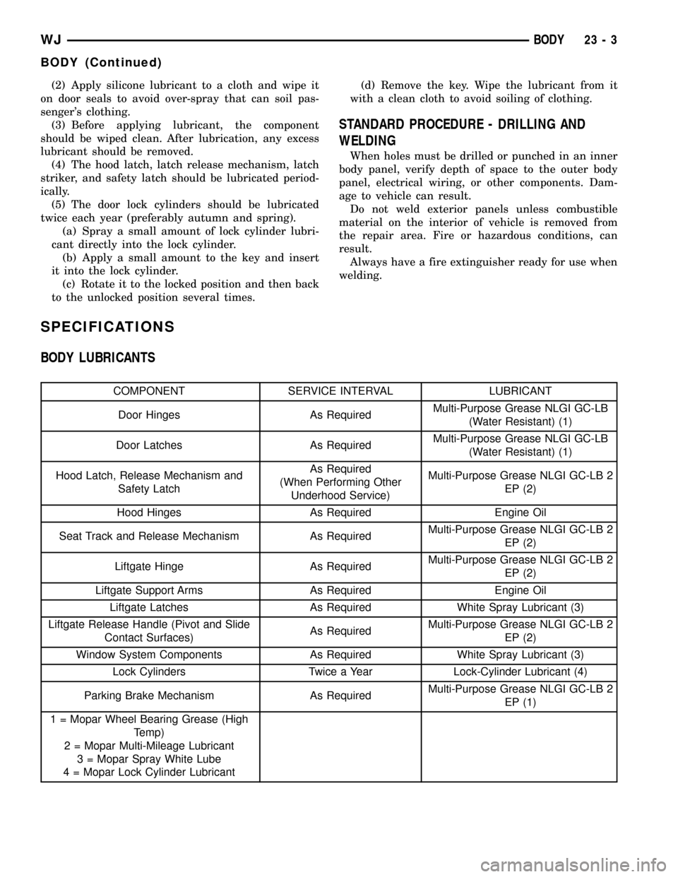
BODY LUBRICANTS
COMPONENT SERVICE INTERVAL LUBRICANT
Door Hinges As RequiredMulti-Purpose Grease NLGI GC-LB
(Water Resistant) (1)
Door Latches As RequiredMulti-Purpose Grease NLGI GC-LB
(Water Resistant) (1)
Hood Latch, Release Mechanism and
Safety LatchAs Required
(When Performing Other
Underhood Service)Multi-Purpose Grease NLGI GC-LB 2
EP (2)
Hood Hinges As Required Engine Oil
Seat Track and Release Mechanism As RequiredMulti-Purpose Grease NLGI GC-LB 2
EP (2)
Liftgate Hinge As RequiredMulti-Purpose Grease NLGI GC-LB 2
EP (2)
Liftgate Support Arms As Required Engine Oil
Liftgate Latches As Required White Spray Lubricant (3)
Liftgate Release Handle (Pivot and Slide
Contact Surfaces)As RequiredMulti-Purpose Grease NLGI GC-LB 2
EP (2)
Window System Components As Required White Spray Lubricant (3)
Lock Cylinders Twice a Year Lock-Cylinder Lubricant (4)
Parking Brake Mechanism As RequiredMulti-Purpose Grease NLGI GC-LB 2
EP (1)
1 = Mopar Wheel Bearing Grease (High
Temp)
2 = Mopar Multi-Mileage Lubricant
3 = Mopar Spray White Lube
4 = Mopar Lock Cylinder Lubricant
WJBODY 23 - 3
BODY (Continued)
Page 1955 of 2199

PAINT TOUCH-UP
DESCRIPTION
When a painted metal surface has been scratched
or chipped, it should be touched-up as soon as possi-
ble to avoid corrosion. For best results, use Mopart
Scratch Filler/Primer, Touch-Up Paints and Clear Top
Coat. Refer to Introduction group of this manual for
Body Code Plate information.
WARNING: USE AN OSHA APPROVED BREATHING
FILTER WHEN SPRAYING PAINT OR SOLVENTS IN
A CONFINED AREA. PERSONAL INJURY CAN
RESULT.
OPERATION
(1) Scrape loose paint and corrosion from inside
scratch or chip.
(2) Clean affected area with MopartTar/Road Oil
Remover, and allow to dry.
(3) Fill the inside of the scratch or chip with a coat
of filler/primer. Do not overlap primer onto good sur-
face finish. The applicator brush should be wet
enough to puddle-fill the defect without running. Do
not stroke brush applicator on body surface. Allow
the filler/primer to dry hard.
(4) Cover the filler/primer with color touch-up
paint. Do not overlap touch-up color onto the original
color coat around the scratch or chip. Butt the new
color to the original color, if possible. Do not stroke
applicator brush on body surface. Allow touch-up
paint to dry hard.
(5) On vehicles without clear coat, the touch-up
color can be lightly finesse sanded (1500 grit) and
polished with rubbing compound.
(6) On vehicles with clear coat, apply clear top coat
to touch-up paint with the same technique as
described in Step 4. Allow clear top coat to dry hard.
If desired, Step 5 can be performed on clear top coat.
WARNING: AVOID PROLONGED SKIN CONTACT
WITH PETROLEUM OR ALCOHOL ± BASED CLEAN-
ING SOLVENTS. PERSONAL INJURY CAN RESULT.
AVOID PROLONGED SKIN CONTACT WITH PETRO-
LEUM OR ALCOHOL ± BASED CLEANING SOL-
VENTS. PERSONAL INJURY CAN RESULT.
FINESSE SANDING/BUFFING &
POLISHING
DESCRIPTION
CAUTION: Do not remove more than .5 mils of
clearcoat finish, if equipped. Base coat paint must
retain clear coat for durability.
Use a Paint Thickness Gauge #PR-ETG-2X or equiv-
alent to determine film thickness before and after
the repair.
Minor acid etching, orange peel, or smudging in
clearcoat or single-stage finishes can be reduced with
light finesse sanding, hand buffing, and polishing.If
the finish has been finesse sanded in the past,
it cannot be repeated. Finesse sanding opera-
tion should be performed by a trained automo-
tive paint technician.
23 - 82 PAINTWJ
Page 2079 of 2199

OPERATION
OPERATION - HEATER AND AIR CONDITIONER
Outside fresh air enters the vehicle through the
cowl top opening at the base of the windshield, and
passes through a plenum chamber to the HVAC sys-
tem blower housing. Air flow velocity can then be
adjusted with the blower motor speed selector switch
on the a/c heater control panel. The air intake open-
ings must be kept free of snow, ice, leaves, and other
obstructions for the HVAC system to receive a suffi-
cient volume of outside air.
It is also important to keep the air intake openings
clear of debris because leaf particles and other debris
that is small enough to pass through the cowl ple-
num screen can accumulate within the HVAC hous-
ing. The closed, warm, damp and dark environment
created within the HVAC housing is ideal for the
growth of certain molds, mildews and other fungi.
Any accumulation of decaying plant matter provides
an additional food source for fungal spores, which
enter the housing with the fresh air. Excess debris,
as well as objectionable odors created by decaying
plant matter and growing fungi can be discharged
into the passenger compartment during HVAC sys-
tem operation.
Both the manual and AZC heater and air condi-
tioner are blend-air type systems. In a blend-air sys-
tem, a blend door controls the amount of
unconditioned air (or cooled air from the evaporator)
that is allowed to flow through, or around, the heater
core. A temperature control knob on the a/c heater
control panel determines the discharge air tempera-
ture by energizing the blend door actuator, which
operates the blend door. This allows an almost imme-
diate control of the output air temperature of the sys-
tem. The AZC system will have separate blend doors
and temperature controls for each front seat occu-
pant.
The mode control knob on the a/c heater control
panel is used to direct the conditioned air to the
selected system outlets. On manual temperature con-
trol systems, the mode control knob switches engine
vacuum to control the mode doors, which are oper-
ated by vacuum actuators. On AZC systems, the
mode control knob switches electrical current to con-
trol the mode doors, which are operated by electronic
actuators.
The outside air intake can be shut off on manual
temperature control systems by selecting the Recircu-
lation Mode with the mode control knob. The outside
air intake can be shut off on Automatic Zone Control
(AZC) type system by pushing the Recirculation
Mode button. This will operate the recirculation door
that closes off the outside fresh air intake and recir-
culates the air that is already inside the vehicle.The air conditioner for all models is designed for
the use of non-CFC, R-134a refrigerant. The air con-
ditioning system has an evaporator to cool and dehu-
midify the incoming air prior to blending it with the
heated air. This air conditioning system uses a ther-
mal expansion valve to meter refrigerant flow to the
evaporator coil. To maintain minimum evaporator
temperature and prevent evaporator freezing, the
system utilizes an evaporator thermister probe with
the appropriate operating logic located in the body
control module (BCM).
OPERATION - REFRIGERANT SYSTEM SERVICE
PORT
The high pressure service port is located on the liq-
uid line near the receiver/drier. The low pressure ser-
vice port is located on the suction line near the
evaporator at the rear of the engine compartment.
Each of the service ports has a threaded plastic
protective cap installed over it from the factory. After
servicing the refrigerant system, always reinstall
both of the service port caps.
DIAGNOSIS AND TESTING
DIAGNOSIS AND TESTING - A/C
PERFORMANCE
The air conditioning system is designed to provide
the passenger compartment with low temperature
and low specific humidity air. The evaporator, located
in the HVAC housing on the dash panel below the
instrument panel, is cooled to temperatures near the
freezing point. As warm damp air passes through the
cooled evaporator, the air transfers its heat to the
refrigerant in the evaporator and the moisture in the
air condenses on the evaporator fins. During periods
of high heat and humidity, an air conditioning sys-
tem will be more effective in the Recirculation Mode.
With the system in the Recirculation Mode, only air
from the passenger compartment passes through the
evaporator. As the passenger compartment air dehu-
midifies, the air conditioning system performance
levels improve.
Humidity has an important bearing on the tempera-
ture of the air delivered to the interior of the vehicle. It
is important to understand the effect that humidity has
on the performance of the air conditioning system.
When humidity is high, the evaporator has to perform a
double duty. It must lower the air temperature, and it
must lower the temperature of the moisture in the air
that condenses on the evaporator fins. Condensing the
moisture in the air transfers heat energy into the evap-
orator fins and tubing. This reduces the amount of heat
the evaporator can absorb from the air. High humidity
greatly reduces the ability of the evaporator to lower
the temperature of the air.
24 - 2 HEATING & AIR CONDITIONINGWJ
HEATING & AIR CONDITIONING (Continued)
Page 2081 of 2199
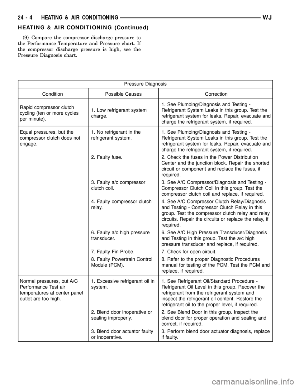
(9) Compare the compressor discharge pressure to
the Performance Temperature and Pressure chart. If
the compressor discharge pressure is high, see the
Pressure Diagnosis chart.
Pressure Diagnosis
Condition Possible Causes Correction
Rapid compressor clutch
cycling (ten or more cycles
per minute).1. Low refrigerant system
charge.1. See Plumbing/Diagnosis and Testing -
Refrigerant System Leaks in this group. Test the
refrigerant system for leaks. Repair, evacuate and
charge the refrigerant system, if required.
Equal pressures, but the
compressor clutch does not
engage.1. No refrigerant in the
refrigerant system.1. See Plumbing/Diagnosis and Testing -
Refrigerant System Leaks in this group. Test the
refrigerant system for leaks. Repair, evacuate and
charge the refrigerant system, if required.
2. Faulty fuse. 2. Check the fuses in the Power Distribution
Center and the junction block. Repair the shorted
circuit or component and replace the fuses, if
required.
3. Faulty a/c compressor
clutch coil.3. See A/C Compressor/Diagnosis and Testing -
Compressor Clutch Coil in this group. Test the
compressor clutch coil and replace, if required.
4. Faulty compressor clutch
relay.4. See A/C Compressor Clutch Relay/Diagnosis
and Testing - Compressor Clutch Relay in this
group. Test the compressor clutch relay and relay
circuits. Repair the circuits or replace the relay, if
required.
6. Faulty a/c high pressure
transducer.6. See A/C High Pressure Transducer/Diagnosis
and Testing in this group. Test the a/c high
pressure transducer and replace, if required.
7. Faulty Fin Probe. 7. Check for open circuit.
8. Faulty Powertrain Control
Module (PCM).8. Refer to the proper Diagnostic Procedures
manual for testing of the PCM. Test the PCM and
replace, if required.
Normal pressures, but A/C
Performance Test air
temperatures at center panel
outlet are too high.1. Excessive refrigerant oil in
system.1. See Refrigerant Oil/Standard Procedure -
Refrigerant Oil Level in this group. Recover the
refrigerant from the refrigerant system and
inspect the refrigerant oil content. Restore the
refrigerant oil to the proper level, if required.
2. Blend door inoperative or
sealing improperly.2. See Blend Door in this group. Inspect the
blend door for proper operation and sealing and
correct, if required.
3. Blend door actuator faulty
or inoperative.3. Perform blend door actuator diagnosis, replace
if faulty.
24 - 4 HEATING & AIR CONDITIONINGWJ
HEATING & AIR CONDITIONING (Continued)
Page 2082 of 2199
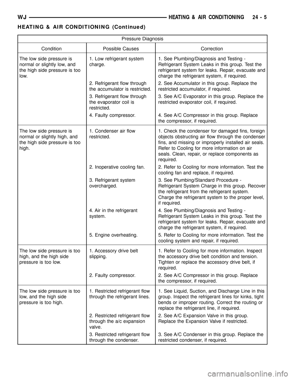
Pressure Diagnosis
Condition Possible Causes Correction
The low side pressure is
normal or slightly low, and
the high side pressure is too
low.1. Low refrigerant system
charge.1. See Plumbing/Diagnosis and Testing -
Refrigerant System Leaks in this group. Test the
refrigerant system for leaks. Repair, evacuate and
charge the refrigerant system, if required.
2. Refrigerant flow through
the accumulator is restricted.2. See Accumulator in this group. Replace the
restricted accumulator, if required.
3. Refrigerant flow through
the evaporator coil is
restricted.3. See A/C Evaporator in this group. Replace the
restricted evaporator coil, if required.
4. Faulty compressor. 4. See A/C Compressor in this group. Replace
the compressor, if required.
The low side pressure is
normal or slightly high, and
the high side pressure is too
high.1. Condenser air flow
restricted.1. Check the condenser for damaged fins, foreign
objects obstructing air flow through the condenser
fins, and missing or improperly installed air seals.
Refer to Cooling for more information on air
seals. Clean, repair, or replace components as
required.
2. Inoperative cooling fan. 2. Refer to Cooling for more information. Test the
cooling fan and replace, if required.
3. Refrigerant system
overcharged.3. See Plumbing/Standard Procedure -
Refrigerant System Charge in this group. Recover
the refrigerant from the refrigerant system.
Charge the refrigerant system to the proper level,
if required.
4. Air in the refrigerant
system.4. See Plumbing/Diagnosis and Testing -
Refrigerant System Leaks in this group. Test the
refrigerant system for leaks. Repair, evacuate and
charge the refrigerant system, if required.
5. Engine overheating. 5. Refer to Cooling for more information. Test the
cooling system and repair, if required.
The low side pressure is too
high, and the high side
pressure is too low.1. Accessory drive belt
slipping.1. Refer to Cooling for more information. Inspect
the accessory drive belt condition and tension.
Tighten or replace the accessory drive belt, if
required.
2. Faulty compressor. 2. See A/C Compressor in this group. Replace
the compressor, if required.
The low side pressure is too
low, and the high side
pressure is too high.1. Restricted refrigerant flow
through the refrigerant lines.1. See Liquid, Suction, and Discharge Line in this
group. Inspect the refrigerant lines for kinks, tight
bends or improper routing. Correct the routing or
replace the refrigerant line, if required.
2. Restricted refrigerant flow
through the a/c expansion
valve.2. See A/C Expansion Valve in this group.
Replace the Expansion Valve if restricted.
3. Restricted refrigerant flow
through the condenser.3. See A/C Condenser in this group. Replace the
restricted condenser, if required.
WJHEATING & AIR CONDITIONING 24 - 5
HEATING & AIR CONDITIONING (Continued)
Page 2084 of 2199
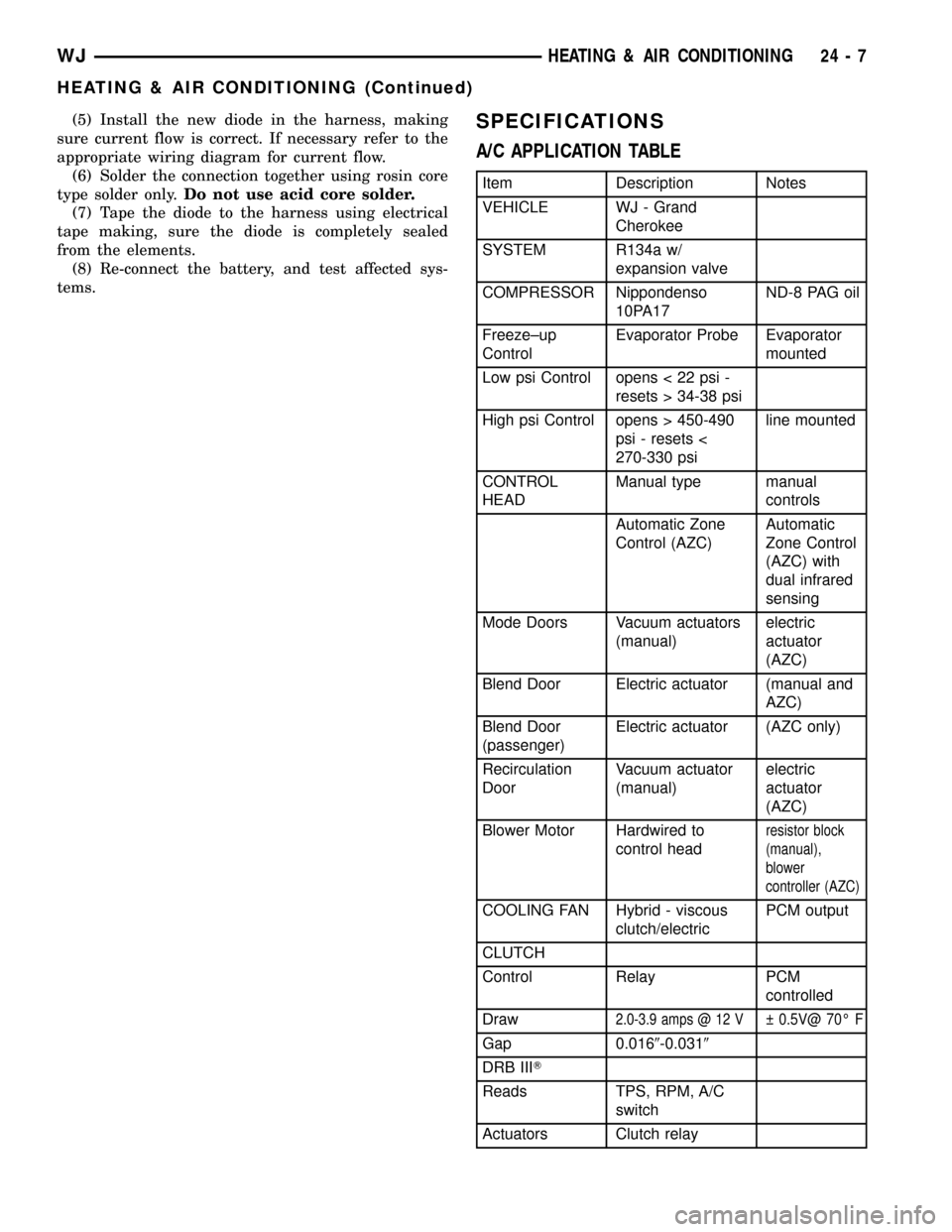
(5) Install the new diode in the harness, making
sure current flow is correct. If necessary refer to the
appropriate wiring diagram for current flow.
(6) Solder the connection together using rosin core
type solder only.Do not use acid core solder.
(7) Tape the diode to the harness using electrical
tape making, sure the diode is completely sealed
from the elements.
(8) Re-connect the battery, and test affected sys-
tems.SPECIFICATIONS
A/C APPLICATION TABLE
Item Description Notes
VEHICLE WJ - Grand
Cherokee
SYSTEM R134a w/
expansion valve
COMPRESSOR Nippondenso
10PA17ND-8 PAG oil
Freeze±up
ControlEvaporator Probe Evaporator
mounted
Low psi Control opens < 22 psi -
resets > 34-38 psi
High psi Control opens > 450-490
psi - resets <
270-330 psiline mounted
CONTROL
HEADManual type manual
controls
Automatic Zone
Control (AZC)Automatic
Zone Control
(AZC) with
dual infrared
sensing
Mode Doors Vacuum actuators
(manual)electric
actuator
(AZC)
Blend Door Electric actuator (manual and
AZC)
Blend Door
(passenger)Electric actuator (AZC only)
Recirculation
DoorVacuum actuator
(manual)electric
actuator
(AZC)
Blower Motor Hardwired to
control head
resistor block
(manual),
blower
controller (AZC)
COOLING FAN Hybrid - viscous
clutch/electricPCM output
CLUTCH
Control Relay PCM
controlled
Draw
2.0-3.9 amps @ 12 V 0.5V@ 70É F
Gap 0.0169-0.0319
DRB IIIT
Reads TPS, RPM, A/C
switch
Actuators Clutch relay
WJHEATING & AIR CONDITIONING 24 - 7
HEATING & AIR CONDITIONING (Continued)
Page 2086 of 2199

CONTROLS
TABLE OF CONTENTS
page page
CONTROLS
DIAGNOSIS AND TESTING - VACUUM
SYSTEM............................10
A/C COMPRESSOR CLUTCH
DESCRIPTION.........................13
OPERATION...........................13
DIAGNOSIS AND TESTING - COMPRESSOR
CLUTCH COIL........................13
STANDARD PROCEDURE - COMPRESSOR
CLUTCH BREAK-IN....................14
REMOVAL.............................14
INSPECTION..........................15
INSTALLATION.........................15
A/C COMPRESSOR CLUTCH RELAY
DESCRIPTION.........................16
OPERATION...........................16
DIAGNOSIS AND TESTING - A/C
COMPRESSOR CLUTCH RELAY..........16
REMOVAL.............................17
INSTALLATION.........................17
A/C HEATER CONTROL
DESCRIPTION.........................17
OPERATION...........................17
DIAGNOSIS AND TESTING - AUTOMATIC
ZONE CONTROL SYSTEM..............18
REMOVAL.............................24
INSTALLATION.........................25
A/C PRESSURE TRANSDUCER
DESCRIPTION.........................25
OPERATION...........................25
DIAGNOSIS AND TESTING - A/C PRESSURE
TRANSDUCER.......................26
REMOVAL.............................26
INSTALLATION.........................26
BLOWER MOTOR CONTROLLER
DESCRIPTION.........................26
OPERATION...........................26
REMOVAL.............................27
INSTALLATION.........................27
BLOWER MOTOR RESISTOR BLOCK
DESCRIPTION.........................27
OPERATION...........................27
DIAGNOSIS AND TESTING - BLOWER
MOTOR RESISTOR BLOCK..............27
REMOVAL.............................28
INSTALLATION.........................28BLOWER MOTOR SWITCH
DESCRIPTION.........................28
OPERATION...........................28
DIAGNOSIS AND TESTING - BLOWER
MOTOR SWITCH-MANUAL TEMPERATURE
CONTROL SYSTEM....................28
REMOVAL.............................29
IN-CAR TEMPERATURE SENSOR
DESCRIPTION.........................29
OPERATION...........................29
REMOVAL.............................29
BLEND DOOR ACTUATOR
DESCRIPTION.........................30
REMOVAL.............................30
INSTALLATION.........................30
MODE DOOR ACTUATOR
DESCRIPTION.........................30
REMOVAL
REMOVAL - HEAT/DEFROST - PANEL/
DEFROST DOOR ELECTRIC ACTUATOR . . . 31
REMOVAL - HEAT/DEFROST DOOR
VACUUM ACTUATOR..................31
REMOVAL - PANEL/DEFROST DOOR
VACUUM ACTUATOR..................32
INSTALLATION
INSTALLATION - HEAT/DEFROST -
PANEL/DEFROST DOOR ELECTRIC
ACTUATOR..........................32
INSTALLATION - HEAT/DEFROST DOOR
VACUUM ACTUATOR..................33
INSTALLATION - PANEL/DEFROST DOOR
VACUUM ACTUATOR..................33
RECIRCULATION DOOR ACTUATOR
DESCRIPTION.........................33
REMOVAL
REMOVAL - RECIRCULATION DOOR
VACUUM ACTUATOR..................33
REMOVAL - RECIRCULATION DOOR
ELECTRIC ACTUATOR.................33
INSTALLATION
INSTALLATION - RECIRCULATION DOOR
VACUUM ACTUATOR..................34
INSTALLATION - RECIRCULATION DOOR
ELECTRIC ACTUATOR.................34
VACUUM CHECK VALVE
DESCRIPTION.........................34
OPERATION...........................34
REMOVAL.............................34
INSTALLATION.........................34
WJCONTROLS 24 - 9