Heating JEEP GRAND CHEROKEE 2002 WJ / 2.G Service Manual
[x] Cancel search | Manufacturer: JEEP, Model Year: 2002, Model line: GRAND CHEROKEE, Model: JEEP GRAND CHEROKEE 2002 WJ / 2.GPages: 2199, PDF Size: 76.01 MB
Page 415 of 2199
SPARK PLUG OVERHEATING
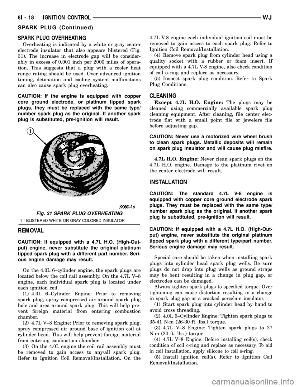
Overheating is indicated by a white or gray center
electrode insulator that also appears blistered (Fig.
31). The increase in electrode gap will be consider-
ably in excess of 0.001 inch per 2000 miles of opera-
tion. This suggests that a plug with a cooler heat
range rating should be used. Over advanced ignition
timing, detonation and cooling system malfunctions
can also cause spark plug overheating.
CAUTION: If the engine is equipped with copper
core ground electrode, or platinum tipped spark
plugs, they must be replaced with the same type/
number spark plug as the original. If another spark
plug is substituted, pre-ignition will result.
REMOVAL
CAUTION: If equipped with a 4.7L H.O. (High-Out-
put) engine, never substitute the original platinum
tipped spark plug with a different part number. Seri-
ous engine damage may result.
On the 4.0L 6±cylinder engine, the spark plugs are
located below the coil rail assembly. On the 4.7L V±8
engine, each individual spark plug is located under
each ignition coil.
(1) 4.0L 6±Cylinder Engine: Prior to removing
spark plug, spray compressed air around spark plug
hole and area around spark plug. This will help pre-
vent foreign material from entering combustion
chamber.
(2) 4.7L V±8 Engine: Prior to removing spark plug,
spray compressed air around base of ignition coil at
cylinder head. This will help prevent foreign material
from entering combustion chamber.
(3) On the 4.0L engine the coil rail assembly must
be removed to gain access to any/all spark plug.
Refer to Ignition Coil Removal/Installation. On the4.7L V-8 engine each individual ignition coil must be
removed to gain access to each spark plug. Refer to
Ignition Coil Removal/Installation.
(4) Remove spark plug from cylinder head using a
quality socket with a rubber or foam insert. If
equipped with a 4.7L V-8 engine, also check condition
of coil o-ring and replace as necessary.
(5) Inspect spark plug condition. Refer to Spark
Plug Conditions.
CLEANING
Except 4.7L H.O. Engine:The plugs may be
cleaned using commercially available spark plug
cleaning equipment. After cleaning, file center elec-
trode flat with a small point file or jewelers file
before adjusting gap.
CAUTION: Never use a motorized wire wheel brush
to clean spark plugs. Metallic deposits will remain
on spark plug insulator and will cause plug misfire.
4.7L H.O. Engine:Never clean spark plugs on the
4.7L H.O. engine. Damage to the platinum rivet on
the center electrode will result.
INSTALLATION
CAUTION: The standard 4.7L V-8 engine is
equipped with copper core ground electrode spark
plugs. They must be replaced with the same type/
number spark plug as the original. If another spark
plug is substituted, pre-ignition will result.
CAUTION: If equipped with a 4.7L H.O. (High-Out-
put) engine, never substitute the original platinum
tipped spark plug with a different type/part number.
Serious engine damage may result.
Special care should be taken when installing spark
plugs into cylinder head spark plug wells. Be sure
plugs do not drop into plug wells as ground straps
may be bent resulting in a change in plug gap, or
electrodes can be damaged.
Always tighten spark plugs to specified torque. Over
tightening can cause distortion resulting in a change
in spark plug gap or a cracked porcelain insulator.
(1) Start spark plug into cylinder head by hand to
avoid cross threading.
(2) 4.0L 6±Cylinder Engine: Tighten spark plugs to
35-41 N´m (26-30 ft. lbs.) torque.
(3) 4.7L V±8 Engine: Tighten spark plugs to 27
N´m (20 ft. lbs.) torque.
(4)
4.7L V±8 Engine: Before installing coil(s), check
condition of coil o-ring and replace as necessary. To aid
in coil installation, apply silicone to coil o-ring.
(5) Install ignition coil(s). Refer to Ignition Coil
Removal/Installation.
Fig. 31 SPARK PLUG OVERHEATING
1 - BLISTERED WHITE OR GRAY COLORED INSULATOR
8I - 18 IGNITION CONTROLWJ
SPARK PLUG (Continued)
Page 450 of 2199
ing the system voltage is high (system voltage is
about sixteen volts or higher), the gauge needle is
moved to the relative voltage position in the red zone
of the gauge scale and the check gauges indicator is
illuminated. The gauge needle remains in the red
zone and the check gauges indicator remains illumi-
nated until the cluster receives a message from the
PCM indicating there is no high system voltage con-
dition (system voltage is below about sixteen volts,
but higher than about eleven volts).
²Communication Error- If the cluster fails to
receive a system voltage message, it will hold the
gauge needle at the last indication for about twelve
seconds, until a new message is received, or until the
ignition switch is turned to the Off position, which-
ever occurs first. After twelve seconds, the cluster
will return the gauge needle to the low end of the
gauge scale.
²Actuator Test- Each time the cluster is put
through the actuator test, the gauge needle will be
swept across the entire gauge scale and back to con-
firm the functionality of the gauge and the cluster
control circuitry.
The PCM continually monitors the system voltage
to control the generator output. The PCM then sends
the proper system voltage messages to the instru-
ment cluster. For further diagnosis of the voltage
gauge or the instrument cluster circuitry that con-
trols the gauge, (Refer to 8 - ELECTRICAL/INSTRU-
MENT CLUSTER - DIAGNOSIS AND TESTING). If
the instrument cluster turns on the check gauges
indicator due to a system voltage low or high condi-
tion, it may indicate that the charging system
requires service. For proper diagnosis of the charging
system, the PCI data bus, or the electronic message
inputs to the instrument cluster that control the volt-
age gauge, a DRBIIItscan tool is required. Refer to
the appropriate diagnostic information.
WAIT-TO-START INDICATOR
DESCRIPTION
A wait-to-start indicator is only found in the
instrument clusters of vehicles equipped with an
optional diesel engine. The wait-to-start indicator is
located near the lower edge of the tachometer gauge
dial face, to the right of center. The wait-to-start
indicator consists of an International Control and
Display Symbol icon for ªDiesel Preheatº imprinted
on an amber lens. The lens is located behind a cutout
in the opaque layer of the tachometer gauge dial face
overlay. The dark outer layer of the gauge dial face
overlay prevents the icon from being clearly visible
when the indicator is not illuminated. The icon
appears silhouetted against an amber field throughthe translucent outer layer of the gauge dial face
overlay when the indicator is illuminated from
behind by a replaceable incandescent bulb and bulb
holder unit located on the instrument cluster elec-
tronic circuit board. The wait-to-start indicator lens
is serviced as a unit with the instrument cluster.
OPERATION
The wait-to-start indicator gives an indication to
the vehicle operator when the diesel engine glow
plugs are energized in their preheat operating mode.
This indicator is controlled by a transistor on the
instrument cluster circuit board based upon cluster
programming and electronic messages received by
the cluster from the Powertrain Control Module
(PCM) over the Programmable Communications
Interface (PCI) data bus. The wait-to-start indicator
bulb is completely controlled by the instrument clus-
ter logic circuit, and that logic will only allow this
indicator to operate when the instrument cluster
receives a battery current input on the fused ignition
switch output (run-start) circuit. Therefore, the indi-
cator will always be off when the ignition switch is in
any position except On or Start. The bulb only illu-
minates when it is switched to ground by the instru-
ment cluster transistor. The instrument cluster will
turn on the wait-to-start indicator for the following
reasons:
²Wait-To-Start Indicator Lamp-On Message-
Each time the cluster receives a wait-to-start indica-
tor lamp-on message from the PCM indicating the
glow plugs are heating and the driver must wait to
start the engine, the wait-to-start indicator will be
illuminated. The indicator remains illuminated until
the cluster receives a wait-to-start indicator lamp-off
message, or until the ignition switch is turned to the
Off position, whichever occurs first.
²Actuator Test- Each time the cluster is put
through the actuator test, the wait-to-start indicator
will be turned on for the duration of the test to con-
firm the functionality of the bulb and the cluster con-
trol circuitry.
The PCM continually monitors the ambient tem-
perature and the glow plug pre-heater circuits to
determine how long the glow plugs must be heated in
the pre-heat operating mode. The PCM then sends
the proper wait-to-start indicator lamp-on and lamp-
off messages to the instrument cluster. If the wait-to-
start indicator fails to light during the actuator test,
replace the bulb with a known good unit. For further
diagnosis of the wait-to-start indicator or the instru-
ment cluster circuitry that controls the indicator,
(Refer to 8 - ELECTRICAL/INSTRUMENT CLUS-
TER - DIAGNOSIS AND TESTING). For proper
diagnosis of the glow plug pre-heater control circuits,
the PCM, the PCI data bus, or the electronic message
WJINSTRUMENT CLUSTER 8J - 35
VOLTAGE GAUGE (Continued)
Page 512 of 2199
POWER MIRROR SWITCH
DESCRIPTION
Both the right and left power outside mirrors are
controlled by a single multi-function switch unit
located on the driver side front door trim panel. The
power mirror switch unit includes a three-position
rocker selector switch and four momentary direc-
tional push button switches.
The power mirror switch unit is integral to the
Driver Door Module (DDM). The power mirror switch
cannot be repaired or adjusted and, if faulty or dam-
aged, the entire DDM unit must be replaced. (Refer
to 8 - ELECTRICAL/ELECTRONIC CONTROL
MODULES/DRIVER DOOR MODULE - REMOVAL)
for the DDM service procedures.
OPERATION
The power mirror selector switch is moved right
(right mirror control), left (left mirror control), or
center to turn the power outside mirror system off.
When the selector switch is in the right mirror con-
trol or left mirror control position, one of the four
directional control buttons is depressed to control
movement of the selected mirror up, down, right, or
left. When the selector switch is in the Off position,
depressing any of the directional switches will not
change either mirror position.
See the owner's manual in the vehicle glove box for
more information on the features, use and operation
of the power mirror switches.
SIDEVIEW MIRROR
DESCRIPTION
Mechanically folding, power operated outside rear
view mirrors are standard equipment on this model.
Each power mirror housing contains two electric
motors, two drive mechanisms, an electric heating
grid, the mirror glass case and the mirror glass. One
motor and drive controls mirror up-and-down (verti-
cal) movement, and the other controls right-and-left
(horizontal) movement. If the vehicle is equipped
with the optional memory system, each mirror head
also contains two position potentiometers. One posi-
tion potentiometer monitors the vertical mirror
motor, and the other monitors the horizontal mirror
motor.
An optional driver side automatic dimming mirror
is able to automatically change its reflectance level.
This mirror is controlled by the circuitry of the auto-
matic day/night inside rear view mirror. A thin layer
of electrochromic material between two pieces of con-
ductive glass make up the face of the mirror. (Refer
to 8 - ELECTRICAL/POWER MIRRORS/AUTO-MATIC DAY / NIGHT MIRROR - DESCRIPTION) for
more information on this feature.
The power mirror unit cannot be repaired. Only
the mirror glass and glass case are serviced sepa-
rately. The replacement mirror glass is supplied with
an instruction sheet that details the recommended
replacement procedure. If any other component of the
power mirror unit is faulty or damaged, the entire
power mirror unit must be replaced.
OPERATION
Each of the two outside power mirrors includes two
reversible electric motors that are secured within the
power mirror housing. Each motor moves the mirror
case and glass through an integral drive unit. When
a power mirror motor is supplied with battery cur-
rent and ground, it moves the mirror case and glass
through its drive unit in one direction. When the bat-
tery current and ground feeds to the motor are
reversed, it moves the mirror case and glass in the
opposite direction.
The power mirrors are equipped with a standard
equipment electric heating grid that is applied to the
back of each outside rear view mirror glass. When an
electrical current is passed through the resistor wire
of the heating grid, it warms the mirror glass. (Refer
to 8 - ELECTRICAL/HEATED MIRRORS -
DESCRIPTION) for more information on the opera-
tion of the heated mirrors and the rear window
defogger system.
If the driver side mirror is equipped with the auto-
matic dimming outside mirror option, two photocell
sensors on the inside rear view mirror are used to
monitor light levels and adjust the reflectance of both
the inside and driver side outside mirrors. This
change in reflectance helps to reduce the glare of
headlamps approaching the vehicle from the rear.
(Refer to 8 - ELECTRICAL/POWER MIRRORS/AU-
TOMATIC DAY / NIGHT MIRROR - OPERATION)
for more information on this feature.
If the vehicle is equipped with the optional mem-
ory system, the Driver Door Module (DDM) and the
Passenger Door Module (PDM) store the mirror posi-
tion information as monitored through the mirror
motor position potentiometers. When the memory
system requests a recall of the stored mirror position,
the DDM and the PDM are able to duplicate the
stored mirror positions by moving the mirror motors
until the potentiometer readings match the stored
values.
WJPOWER MIRRORS 8N - 15
Page 1227 of 2199
the same time, the power distribution system was
designed to provide ready access to these electrical
distribution points for the vehicle technician to use
when conducting diagnosis and repair of faulty cir-
cuits. The power distribution system can also prove
useful for the sourcing of additional electrical circuits
that may be required to provide the electrical current
needed to operate accessories that the vehicle owner
may choose to have installed in the aftermarket.
NOTE: DO NOT ATTEMPT TO SWAP POWER DIS-
TRIBUTION CENTERS FROM ONE VEHICLE TO
ANOTHER. MOST OF THESE ASSEMBLIES ARE
VEHICLE FEATURE SPECIFIC AND THEREFORE
NOT INTERCHANGEABLE. ALWAYS USE THE COR-
RECT PART NUMBERED ASSEMBLY WHEN DIAG-
NOSING OR REPLACING A POWER DISTRIBUTION
CENTER.
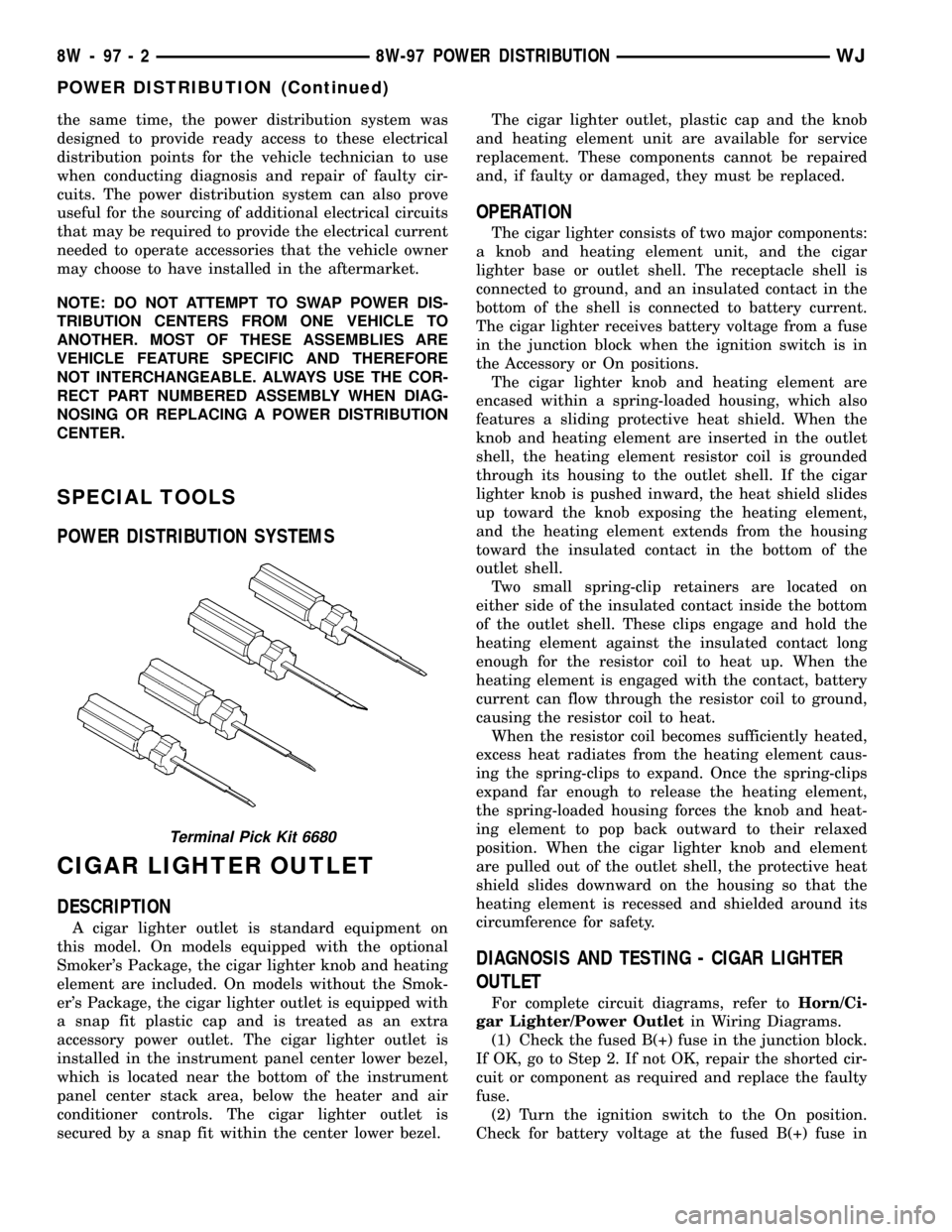
SPECIAL TOOLS
POWER DISTRIBUTION SYSTEMS
CIGAR LIGHTER OUTLET
DESCRIPTION
A cigar lighter outlet is standard equipment on
this model. On models equipped with the optional
Smoker's Package, the cigar lighter knob and heating
element are included. On models without the Smok-
er's Package, the cigar lighter outlet is equipped with
a snap fit plastic cap and is treated as an extra
accessory power outlet. The cigar lighter outlet is
installed in the instrument panel center lower bezel,
which is located near the bottom of the instrument
panel center stack area, below the heater and air
conditioner controls. The cigar lighter outlet is
secured by a snap fit within the center lower bezel.The cigar lighter outlet, plastic cap and the knob
and heating element unit are available for service
replacement. These components cannot be repaired
and, if faulty or damaged, they must be replaced.
OPERATION
The cigar lighter consists of two major components:
a knob and heating element unit, and the cigar
lighter base or outlet shell. The receptacle shell is
connected to ground, and an insulated contact in the
bottom of the shell is connected to battery current.
The cigar lighter receives battery voltage from a fuse
in the junction block when the ignition switch is in
the Accessory or On positions.
The cigar lighter knob and heating element are
encased within a spring-loaded housing, which also
features a sliding protective heat shield. When the
knob and heating element are inserted in the outlet
shell, the heating element resistor coil is grounded
through its housing to the outlet shell. If the cigar
lighter knob is pushed inward, the heat shield slides
up toward the knob exposing the heating element,
and the heating element extends from the housing
toward the insulated contact in the bottom of the
outlet shell.
Two small spring-clip retainers are located on
either side of the insulated contact inside the bottom
of the outlet shell. These clips engage and hold the
heating element against the insulated contact long
enough for the resistor coil to heat up. When the
heating element is engaged with the contact, battery
current can flow through the resistor coil to ground,
causing the resistor coil to heat.
When the resistor coil becomes sufficiently heated,
excess heat radiates from the heating element caus-
ing the spring-clips to expand. Once the spring-clips
expand far enough to release the heating element,
the spring-loaded housing forces the knob and heat-
ing element to pop back outward to their relaxed
position. When the cigar lighter knob and element
are pulled out of the outlet shell, the protective heat
shield slides downward on the housing so that the
heating element is recessed and shielded around its
circumference for safety.
DIAGNOSIS AND TESTING - CIGAR LIGHTER
OUTLET
For complete circuit diagrams, refer toHorn/Ci-
gar Lighter/Power Outletin Wiring Diagrams.
(1) Check the fused B(+) fuse in the junction block.
If OK, go to Step 2. If not OK, repair the shorted cir-
cuit or component as required and replace the faulty
fuse.
(2) Turn the ignition switch to the On position.
Check for battery voltage at the fused B(+) fuse in
Terminal Pick Kit 6680
8W - 97 - 2 8W-97 POWER DISTRIBUTIONWJ
POWER DISTRIBUTION (Continued)
Page 1237 of 2199
PDC LOWER COVER INSTALLATION
(1) Align the PDC housing lower cover on the bot-
tom of the PDC.
(2) Evenly press the lower cover into place until
latches are fully engaged.
(3) Where the right headlamp and dash harness
enters the PDC, tape the harness securely to the
trough formation on the PDC lower cover.
(4) Install the PDC in its mounting location on the
battery support.
(5) Install the battery wire harness over the two
PDC B+ terminal studs. Torque the nuts to 11.3 N´m
(100 in. lbs.).
(6) Install the battery. Refer to Battery System for
the procedure.
(7) Install the PDC cover.
INSTALLATION
The Power Distribution Center (PDC) main hous-
ing unit, the PDC fuse wedges and the PDC bus bars
cannot be repaired and are only serviced as a unit
with the right headlamp and dash wire harness. If
the PDC main housing unit, the fuse wedges or the
bus bars are faulty or damaged, the entire PDC and
right headlamp and dash wire harness unit must be
replaced.
(1) Position the PDC and the right headlamp and
dash wire harness unit in the engine compartment.
(2) Engage the PDC housing mounts with the
stanchions of the battery support and push the unit
downward until the mount latches fully engage the
mounting tabs on the stanchions.
(3) Install the two-holed eyelet of the battery wire
harness PDC take outs onto the two PDC B(+) termi-
nal studs.
(4) Install and tighten the nuts that secure the
eyelet of the battery wire harness PDC take outs to
the B(+) terminal studs. Tighten the nuts to 11.3
N´m (100 in. lbs.).
(5) Engage each of the retainers that secure the
right headlamp and dash wire harness to the vehicle
body and chassis components. Refer toConnector
Locationsin Wiring Diagrams for the location of
more information on the right headlamp and dash
wire harness retainer locations.
(6) Install all of the fasteners that secure each of
the right headlamp and dash wire harness ground
eyelets to the vehicle body and chassis components.
Refer toConnector Locationsin Wiring Diagrams
for the location of more information on the ground
eyelet locations.
(7) Reconnect each of the right headlamp and dash
wire harness connectors. Refer toConnector Loca-
tionsin Wiring Diagrams for the location of more
information on the right headlamp and dash wire
harness connector locations. For connectors securedwith screws, tighten the screws to 4.3 N´m (38 in.
lbs.).
(8) Reconnect the battery negative cable.
POWER OUTLET
DESCRIPTION - FRONT POWER OUTLET
An accessory power outlet is standard equipment
on this model. The power outlet is installed in the
instrument panel center lower bezel, which is located
near the bottom of the instrument panel center stack
area, below the heater and air conditioner controls.
The power outlet base is secured by a snap fit within
the center lower bezel. A hinged door with an over-
center spring flips closed to conceal and protect the
power outlet base when the power outlet is not being
used, and flips open below the center lower bezel
while the power outlet is in use.
The power outlet receptacle unit and the power
outlet door are each available for service replace-
ment.
OPERATION - FRONT POWER OUTLET
The power outlet base or receptacle shell is con-
nected to ground, and an insulated contact in the
bottom of the shell is connected to battery current.
The power outlet receives battery voltage from a fuse
in the junction block at all times.
While the power outlet is very similar to a cigar
lighter base unit, it does not include the two small
spring-clip retainers inside the bottom of the recepta-
cle shell that are used to secure the cigar lighter
heating element to the insulated contact.
DIAGNOSIS AND TESTING - POWER OUTLET
For complete circuit diagrams, refer toHorn/Ci-
gar Lighter/Power Outletin Wiring Diagrams.
WARNING: REFER TO RESTRAINTS BEFORE
ATTEMPTING ANY STEERING WHEEL, STEERING
COLUMN, OR INSTRUMENT PANEL COMPONENT
DIAGNOSIS OR SERVICE. FAILURE TO TAKE THE
PROPER PRECAUTIONS COULD RESULT IN ACCI-
DENTAL AIRBAG DEPLOYMENT AND POSSIBLE
PERSONAL INJURY.
(1) Check the fused B(+) fuse in the junction block.
If OK, go to Step 2. If not OK, repair the shorted cir-
cuit or component as required and replace the faulty
fuse.
(2) Check for battery voltage at the fused B(+) fuse
in the junction block. If OK, go to Step 3. If not OK,
repair the open fused B(+) circuit to the Power Dis-
tribution Center (PDC) fuse as required.
(3) Open the power outlet door. Check for continu-
ity between the inside circumference of the power
8W - 97 - 12 8W-97 POWER DISTRIBUTIONWJ
POWER DISTRIBUTION CENTER (Continued)
Page 1242 of 2199
the vehicle. The power outlet base and mount are
secured by a snap fit within the quarter trim panel.
A plastic protective cap snaps into the power outlet
base when the power outlet is not being used, and
hangs from the power outlet base mount by an inte-
gral bail strap while the power outlet is in use. While
the power outlet is very similar to a cigar lighter
base unit, it does not include the two small spring-
clip retainers inside the bottom of the receptacle
shell that are used to secure the cigar lighter heating
element to the insulated contact.
The power outlet receptacle unit and the accessory
power outlet protective cap are available for service.
The power outlet receptacle cannot be repaired and,
if faulty or damaged, it must be replaced.
OPERATION - REAR POWER OUTLET
The power outlet base or receptacle shell is con-
nected to ground, and an insulated contact in the
bottom of the shell is connected to battery current.
The power outlet receives battery voltage from a fuse
in the Power Distribution Center (PDC) through a
fuse in the Junction Block (JB) at all times. Refer to
Horn/Cigar Lighter/Power Outletin Wiring Dia-
grams for the location of complete rear power outlet
circuit diagrams.
DIAGNOSIS AND TESTING - REAR POWER
OUTLET
Refer toHorn/Cigar Lighter/Power Outletin
Wiring Diagrams for the location of complete rear
power outlet circuit diagrams.
(1) Check the fused B(+) fuse in the Junction
Block (JB). If OK, go to Step 2. If not OK, repair the
shorted circuit or component as required and replace
the faulty fuse.
(2) Check for battery voltage at the fused B(+) fuse
in the JB. If OK, go to Step 3. If not OK, repair the
open fused B(+) circuit to the Power Distribution
Center (PDC) as required.
(3) Remove the plastic protective cap from the rear
power outlet receptacle. Check for continuity between
the inside circumference of the rear power outlet
receptacle and a good ground. There should be conti-
nuity. If OK, go to Step 4. If not OK, go to Step 5.
(4) Check for battery voltage at the insulated con-
tact located at the back of the rear power outlet
receptacle. If not OK, go to Step 5.(5) Disconnect and isolate the battery negative
cable. Remove the rear power outlet from the right
quarter trim panel. Check for continuity between the
ground circuit cavity of the rear power outlet wire
harness connector and a good ground. There should
be continuity. If OK, go to Step 6. If not OK, repair
the open ground circuit to ground as required.
(6) Connect the battery negative cable. Check for
battery voltage at the fused B(+) circuit cavity of the
rear power outlet wire harness connector. If OK,
replace the faulty rear power outlet receptacle base.
If not OK, repair the open fused B(+) circuit to the
JB fuse as required.
REMOVAL
(1) Disconnect and isolate the battery negative
cable.
(2) Pull the protective cap out of the rear power
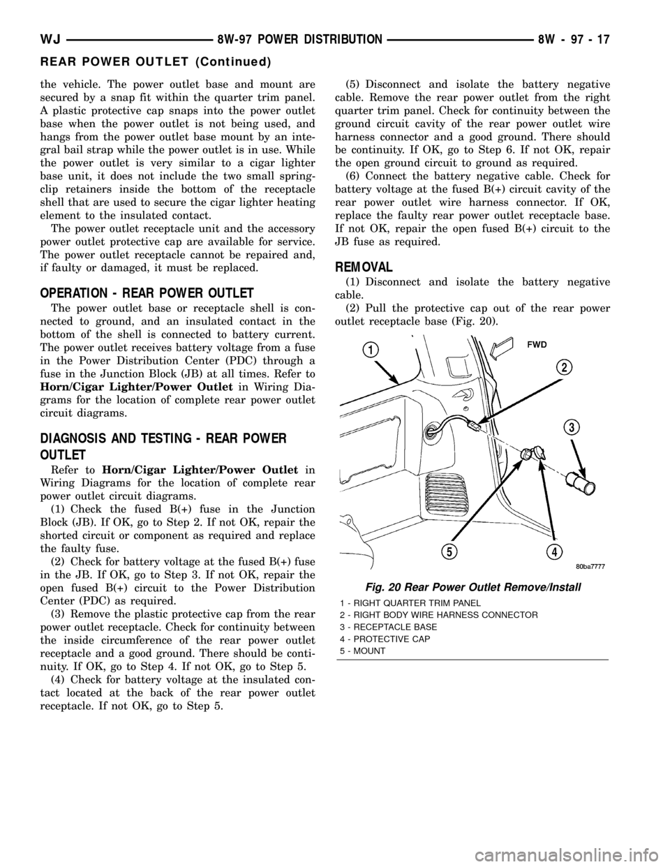
outlet receptacle base (Fig. 20).
Fig. 20 Rear Power Outlet Remove/Install
1 - RIGHT QUARTER TRIM PANEL
2 - RIGHT BODY WIRE HARNESS CONNECTOR
3 - RECEPTACLE BASE
4 - PROTECTIVE CAP
5 - MOUNT
WJ8W-97 POWER DISTRIBUTION 8W - 97 - 17
REAR POWER OUTLET (Continued)
Page 1255 of 2199

(7) Remove the fan assembly from the water pump
(Refer to 7 - COOLING/ENGINE/RADIATOR FAN -
REMOVAL).
(8) Remove the fan shroud.
(9) Disconnect the transmission fluid cooler lines
(automatic transmission).
(10) Discharge the A/C system (Refer to 24 -
HEATING & AIR CONDITIONING/PLUMBING -
STANDARD PROCEDURE).
(11) Remove the service valves and cap the com-
pressor ports.
(12) Remove the radiator or radiator/condenser (if
equipped with A/C).
(13) Disconnect the heater hoses at the engine
thermostat housing and water pump.
(14) Disconnect the accelerator cable, transmission
line pressure cable and speed control cable (if
equipped) from the throttle body.
(15) Remove cables from the bracket and secure
out of the way.
(16) Disconnect the body ground at the engine.
(17) Disconnect the following connectors and
secure their harness out of the way.
²Power steering pressure switch
²Coolant temperature sensor
²Six (6) fuel injector connectors
²Intake air temperature sensor
²Throttle position sensor
²Map sensor
²Crankshaft position sensor
²Oxygen sensor
²Camshaft position sensor
²Generator connector and B+ terminal wire
(18) Disconnect the coil rail electrical connections
and the oil pressure switch connector.
(19) Perform the fuel pressure release procedure
(Refer to 14 - FUEL SYSTEM/FUEL DELIVERY -
STANDARD PROCEDURE).
(20) Disconnect the fuel supply line at the injector
rail (Refer to 14 - FUEL SYSTEM/FUEL DELIVERY/
QUICK CONNECT FITTING - STANDARD PROCE-
DURE).
(21) Remove the fuel line bracket from the intake
manifold.
(22) Remove the air cleaner assembly (Fig. 5).
(23) Disconnect the hoses from the fittings at the
steering gear.
(24) Drain the pump reservoir.
(25) Cap the fittings on the hoses and steering
gear to prevent foreign objects from entering the sys-
tem.
(26) Raise and support the vehicle.
(27) Disconnect the wires from the engine starter
motor solenoid.(28) Remove the engine starter motor (Refer to 8 -
ELECTRICAL/STARTING/STARTER MOTOR -
REMOVAL).
(29) Disconnect the oxygen sensor from the
exhaust pipe.
(30) Disconnect the exhaust pipe from the mani-
fold.
(31) Remove the exhaust pipe support.
(32) Remove the bending brace (Refer to 9 -
ENGINE/ENGINE BLOCK/STRUCT SUPPORT -
REMOVAL).
(33) Remove the engine flywheel/converter housing
access cover.
(34) Mark the converter and drive plate location.
(35) Remove the converter-to-drive plate bolts.
(36) Remove the upper engine flywheel/converter
housing bolts and loosen the bottom bolts.
(37) Remove the engine mount cushion-to-engine
compartment bracket bolts.
(38) Lower the vehicle.
(39) Attach a lifting device to the engine.
(40) Raise the engine off the front supports.
(41) Place a support or floor jack under the con-
verter (or engine flywheel) housing.
(42) Remove the remaining converter (or engine
flywheel) housing bolts.
(43) Lift the engine out of the engine compart-
ment.
Fig. 5 Air Cleaner Assembly
1 - POWER STEERING PUMP
2 - AIR CLEANER ASSEMBLY
9 - 12 ENGINE - 4.0LWJ
ENGINE - 4.0L (Continued)
Page 1256 of 2199

INSTALLATION
CAUTION: When installing the engine into a vehicle
equipped with an automatic transmission, be care-
ful not to damage the trigger wheel on the engine
flywheel.
(1) Attach a lifting device to the engine and lower
the engine into the engine compartment. For easier
installation, it may be necessary to remove the
engine mount bracket as an aid in alignment of the
engine to the transmission.
(2) Align the transmission torque converter hous-
ing with the engine.
(3) Loosely install the converter housing lower
bolts and install the next higher bolt and nut on each
side.
(4) Tighten all 4 bolts finger tight.
(5) Install the engine mount brackets (if removed).
(6) Lower the engine and engine mount brackets
onto the engine compartment cushions. Install the
bolts and finger tighten the nuts.
(7) Remove the engine lifting device.
(8) Raise and support the vehicle.
(9) Install the remaining engine flywheel/converter
housing bolts. Tighten all bolts to 38 N´m (28 ft. lbs.)
torque.
(10) Install the converter-to-drive plate bolts.
(11) Ensure the installation reference marks are
aligned.
(12) Install the engine flywheel/converter housing
access cover.
(13) Install the exhaust pipe support and tighten
the screw.
(14) Install the engine bending brace (Refer to 9 -
ENGINE/ENGINE BLOCK/STRUCT SUPPORT -
INSTALLATION).
(15) Tighten the engine mount-to-bracket bolts.
(16) Connect the vehicle speed sensor wire connec-
tions and tighten the screws.
(17) Connect the exhaust pipe to the manifold.
(18) Install the engine starter motor (Refer to 8 -
ELECTRICAL/STARTING/STARTER MOTOR -
INSTALLATION).
(19) Connect the wires to the engine starter motor
solenoid.
(20) Lower the vehicle.
(21) Connect all the vacuum hoses and wire con-
nectors identified during engine removal.
(22) Remove protective caps from the power steer-
ing hoses.
(23) Connect the hoses to the fittings at the steer-
ing gear. Tighten the nut to 52 N´m (38 ft. lbs.)
torque.
(24) Fill the pump reservoir with fluid.(25) Inspect the fuel supply line o-ring(s) and
replace if necessary. Connect fuel supply line to injec-
tior rail and verify connection by pulling outward on
the line.
(26) Install the fuel line bracket to the intake
manifold.
(27) Connect the coil rail electrical connectors and
oil pressure switch connector.
(28) Connect the following electrical connectors:
²Power steering pressure switch
²Coolant temperature sensor
²Six (6) fuel injector connectors
²Intake air temperature sensor
²Throttle position sensor
²Map sensor
²Crankshaft position sensor
²Oxygen sensor
²Camshaft position sensor
²Generator connector and B+ terminal wire
(29) Connect all previously removed vacuum hoses.
(30) Connect the body ground strap.
(31) Install the throttle, transmission line pres-
sure, and speed control cables to their mounting
bracket and connect them to the throttle body.
(32) Connect the heater hoses at the engine ther-
mostat housing and water pump.
(33) Install the fan assembly (Refer to 7 - COOL-
ING/ENGINE/RADIATOR FAN - INSTALLATION).
(34) Place the fan shroud in position over the fan.
(35) Install the radiator (Refer to 7 - COOLING/
ENGINE/RADIATOR - INSTALLATION).
(36) Connect the service valves to the A/C com-
pressor ports, if equipped with A/C.
(37) Charge the air conditioner system (Refer to 24
- HEATING & AIR CONDITIONING/PLUMBING -
STANDARD PROCEDURE).
(38) Connect the radiator hoses and automatic
transmission fluid cooler pipes, if equipped.
(39) Install the fan shroud to the radiator or radi-
ator/condenser (if equipped with A/C).
(40) Install upper radiator support.
(41) Connect the upper radiator hose and tighten
the clamp.
(42) Connect the lower radiator hose and tighten
the clamp.
(43) Fill crankcase with engine oil. (Refer to
LUBRICATION & MAINTENANCE/FLUID CAPACI-
TIES - SPECIFICATIONS) for correct capacities.
(44) Fill the cooling system with reusable coolant
or new coolant (Refer to 7 - COOLING - STANDARD
PROCEDURE).
(45) Align the hood to the scribe marks. Install the
hood.
(46) Install the air cleaner assembly.
(47) Install the battery and connect the battery
cable.
WJENGINE - 4.0L 9 - 13
ENGINE - 4.0L (Continued)
Page 1265 of 2199

(12) Install the push rods, rocker arms, pivots and
bridges in the order they were removed (Refer to 9 -
ENGINE/CYLINDER HEAD/ROCKER ARM /
ADJUSTER ASSY - INSTALLATION).
(13) Install the engine cylinder head cover (Refer
to 9 - ENGINE/CYLINDER HEAD/CYLINDER
HEAD COVER(S) - INSTALLATION).
(14) Attach the air conditioner compressor mount-
ing bracket to the engine cylinder head and block.
Tighten the bolts to 40 N´m (30 ft. lbs.) torque.
(15) Attach the air conditioning compressor to the
bracket. Tighten the bolts to 27 N´m (20 ft. lbs.)
torque.
CAUTION: The serpentine drive belt must be routed
correctly. Incorrect routing can cause the water
pump to turn in the opposite direction causing the
engine to overheat.
(16) Install the serpentine drive belt. (Refer to 7 -
COOLING/ACCESSORY DRIVE/DRIVE BELTS -
INSTALLATION).
(17) Install the air cleaner and ducting.
(18) Connect the hoses to the engine thermostat
housing and fill the cooling system to the specified
level (Refer to 7 - COOLING - STANDARD PROCE-
DURE).
(19) The automatic transmission throttle linkage
and cable must be adjusted after completing the
engine cylinder head installation (Refer to 21 -
TRANSMISSION/TRANSAXLE/AUTOMATIC - AW4/
THROTTLE VALVE CABLE - ADJUSTMENTS).
(20) Install the temperature sending unit and con-
nect the wire connector.
(21) If equipped with air conditioning, install A/C
compressor (Refer to 24 - HEATING & AIR CONDI-
TIONING/PLUMBING/A/C COMPRESSOR -
INSTALLATION) and charge A/C system (Refer to 24
- HEATING & AIR CONDITIONING/PLUMBING -
STANDARD PROCEDURE).
(22) Connect negative cable to battery.
WARNING: USE EXTREME CAUTION WHEN THE
ENGINE IS OPERATING. DO NOT STAND IN DIRECT
LINE WITH THE FAN. DO NOT PUT HANDS NEAR
THE PULLEYS, BELTS OR FAN. DO NOT WEAR
LOOSE CLOTHING.
(23) Operate the engine with the radiator cap off.
Inspect for leaks and continue operating the engine
until the engine thermostat opens. Add coolant, if
required.CYLINDER HEAD COVER(S)
DESCRIPTION
The cylinder head cover (Fig. 11) is made of
stamped steel and incorporates the Crankcase Venti-
lation (CCV) Hoses and the oil fill opening.
REMOVAL
The cylinder head cover is isolated from the cylin-
der head via grommets and a reusable molded rubber
gasket. The grommet and limiter are retained in the
cylinder head cover.
(1) Disconnect negative cable from battery.
(2) Disconnect the Crankcase Ventilation (CCV)
vacuum hose from engine cylinder head cover.
(3) Disconnect the fresh air inlet hose from the
engine cylinder head cover.
(4) Disconnect the accelerator, transmission, and
speed (if equipped) control cables from the throttle
body (Fig. 12).
(5) Remove the three bolts that fasten the control
cable bracket to the intake manifold.
(6) Remove control cables from cylinder head cover
clip.
(7) Position control cables and bracket away from
cylinder head cover secure with tie straps.
(8) Remove the engine cylinder head cover mount-
ing bolts.
(9) Remove the engine cylinder head cover and
gasket.
Fig. 11 Cylinder Head Cover
9 - 22 ENGINE - 4.0LWJ
CYLINDER HEAD (Continued)
Page 1274 of 2199
REMOVAL
REMOVAL - CAMSHAFT BEARINGS
The camshaft rotates within four steel-shelled,
babbitt-lined bearings that are pressed into the cyl-
inder block and then line reamed. The camshaft
bearing bores and bearing diameters are not the
same size. They are stepped down in 0.254 mm
(0.010 inch) increments from the front bearing (larg-
est) to the rear bearing (smallest). This permits eas-
ier removal and installation of the camshaft. The
camshaft bearings are pressure lubricated. Camshaft
end play is maintained by the thrust plate.
(1) Remove the camshaft (Refer to 9 - ENGINE/
ENGINE BLOCK/CAMSHAFT & BEARINGS (IN
BLOCK) - REMOVAL).
NOTE: It is not advisable to attempt to replace cam-
shaft bearings unless special removal and installa-
tion tools are available, such as recommended tool
8544 Camshaft Bushing Remover Installer.
(2) Using Special tool 8544 Camshaft Bushing
Remover Installer, remove the camshaft bearings.
REMOVAL - CAMSHAFT
WARNING: THE COOLANT IN A RECENTLY OPER-
ATED ENGINE IS HOT AND PRESSURIZED.RELEASE THE PRESSURE BEFORE REMOVING
THE DRAIN COCK, CAP AND DRAIN PLUGS.
(1) Disconnect negative cable from battery.
(2) Drain the cooling system (Refer to 7 - COOL-
ING - STANDARD PROCEDURE).
(3) Remove the radiator (Refer to 7 - COOLING/
ENGINE/RADIATOR - REMOVAL) and condenser
(Refer to 24 - HEATING & AIR CONDITIONING/
PLUMBING/A/C CONDENSER - REMOVAL), if
equipped with A/C.
(4) Remove the engine cylinder head cover (Refer
to 9 - ENGINE/CYLINDER HEAD/CYLINDER
HEAD COVER(S) - REMOVAL).
(5) Remove the rocker arms, bridges and pivots
(Refer to 9 - ENGINE/CYLINDER HEAD/ROCKER
ARM / ADJUSTER ASSY - REMOVAL).
(6) Remove the push rods.
(7) Remove the engine cylinder head and gasket
(Refer to 9 - ENGINE/CYLINDER HEAD - REMOV-
AL).
(8) Remove the hydraulic valve tappets from the
engine cylinder block (Refer to 9 - ENGINE/ENGINE
BLOCK/HYDRAULIC LIFTERS (CAM IN BLOCK) -
REMOVAL).
(9) Remove the vibration damper (Refer to 9 -
ENGINE/ENGINE BLOCK/VIBRATION DAMPER -
REMOVAL).
(10) Remove the timing case cover (Refer to 9 -
ENGINE/VALVE TIMING/TIMING BELT / CHAIN
COVER(S) - REMOVAL).
(11) Rotate the crankshaft until the crankshaft
sprocket timing mark is aligned on centerline with
the camshaft sprocket timing mark (Fig. 32).
(12) Remove the timing chain and sprockets (Refer
to 9 - ENGINE/VALVE TIMING/TIMING BELT/
CHAIN AND SPROCKETS - REMOVAL).
(13) Remove the front bumper and/or grille, as
required.
(14) Remove the two thrust plate retaining screws,
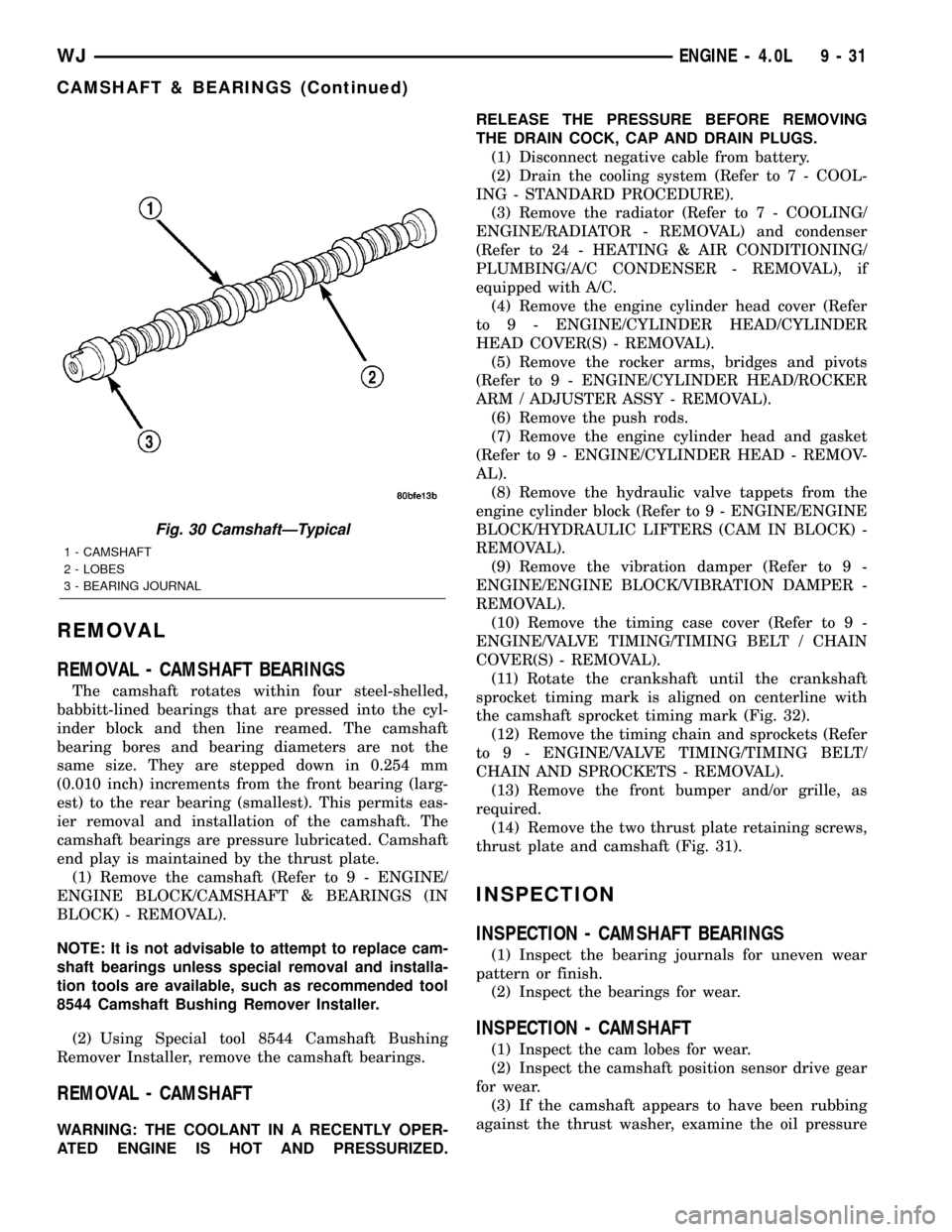
thrust plate and camshaft (Fig. 31).
INSPECTION
INSPECTION - CAMSHAFT BEARINGS
(1) Inspect the bearing journals for uneven wear
pattern or finish.
(2) Inspect the bearings for wear.
INSPECTION - CAMSHAFT
(1) Inspect the cam lobes for wear.
(2) Inspect the camshaft position sensor drive gear
for wear.
(3) If the camshaft appears to have been rubbing
against the thrust washer, examine the oil pressure
Fig. 30 CamshaftÐTypical
1 - CAMSHAFT
2 - LOBES
3 - BEARING JOURNAL
WJENGINE - 4.0L 9 - 31
CAMSHAFT & BEARINGS (Continued)