Valves JEEP GRAND CHEROKEE 2002 WJ / 2.G Service Manual
[x] Cancel search | Manufacturer: JEEP, Model Year: 2002, Model line: GRAND CHEROKEE, Model: JEEP GRAND CHEROKEE 2002 WJ / 2.GPages: 2199, PDF Size: 76.01 MB
Page 1522 of 2199

STANDARD PROCEDURE - TORQUE
CONVERTER DRAINBACK VALVE........134
TRANSMISSION TEMPERATURE SENSOR
DESCRIPTION........................134
OPERATION..........................134
VALVE BODY
DESCRIPTION........................135
OPERATION..........................139REMOVAL............................154
DISASSEMBLY........................155
CLEANING...........................165
INSPECTION.........................166
ASSEMBLY...........................167
INSTALLATION........................175
ADJUSTMENTS - VALVE BODY...........175
AUTOMATIC TRANSMISSION -
42RE
DESCRIPTION
The 42RE is a four speed fully automatic transmis-
sion (Fig. 1) with an electronic governor. The 42RE is
equipped with a lock-up clutch in the torque con-
verter. First through third gear ranges are provided
by the clutches, bands, overrunning clutch, and plan-
etary gear sets in the transmission. Fourth gear
range is provided by the overdrive unit that contains
an overdrive clutch, direct clutch, planetary gear set,
and overrunning clutch.The transmission contains a front, rear, and direct
clutch which function as the input driving compo-
nents. It also contains the kickdown (front) and the
low/reverse (rear) bands which, along with the over-
running clutch and overdrive clutch, serve as the
holding components. The driving and holding compo-
nents combine to select the necessary planetary gear
components, in the front, rear, or overdrive planetary
gear set, transfer the engine power from the input
shaft through to the output shaft.
The valve body is mounted to the lower side of the
transmission and contains the valves to control pres-
sure regulation, fluid flow control, and clutch/band
application. The oil pump is mounted at the front of
the transmission and is driven by the torque con-
verter hub. The pump supplies the oil pressure nec-
essary for clutch/band actuation and transmission
lubrication.
WJAUTOMATIC TRANSMISSION - 42RE 21 - 3
Page 1531 of 2199
CLUTCH AND BAND APPLICATION CHART
SHIFT
LEVER
POSI-
TIONTRANSMISSION CLUTCHES AND BANDS OVERDRIVE CLUTCHES
FRONT
CLUTCHFRONT
BANDREAR
CLUTCHREAR
BANDOVER-
RUNNING
CLUTCHOVER-
DRIVE
CLUTCHDIRECT
CLUTCHOVER-
RUNNING
CLUTCH
Reverse X X X
Drive -
FirstXXXX
Drive -
SecondXX X X
Drive -
ThirdXX XX
Drive -
FourthXX X
Manual
SecondXXXXX
Manual
FirstXX X X X
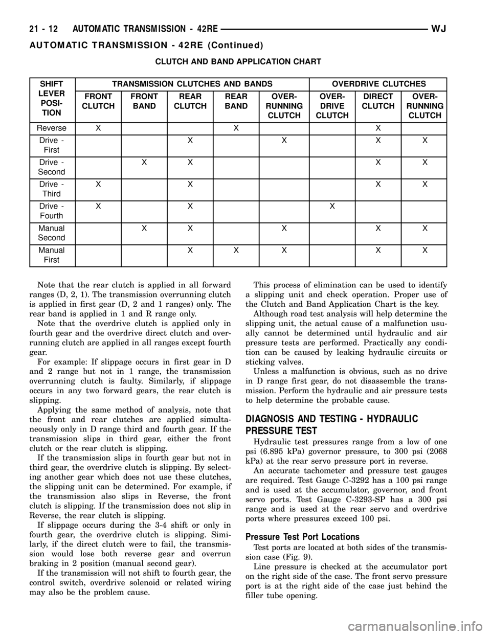
Note that the rear clutch is applied in all forward
ranges (D, 2, 1). The transmission overrunning clutch
is applied in first gear (D, 2 and 1 ranges) only. The
rear band is applied in 1 and R range only.
Note that the overdrive clutch is applied only in
fourth gear and the overdrive direct clutch and over-
running clutch are applied in all ranges except fourth
gear.
For example: If slippage occurs in first gear in D
and 2 range but not in 1 range, the transmission
overrunning clutch is faulty. Similarly, if slippage
occurs in any two forward gears, the rear clutch is
slipping.
Applying the same method of analysis, note that
the front and rear clutches are applied simulta-
neously only in D range third and fourth gear. If the
transmission slips in third gear, either the front
clutch or the rear clutch is slipping.
If the transmission slips in fourth gear but not in
third gear, the overdrive clutch is slipping. By select-
ing another gear which does not use these clutches,
the slipping unit can be determined. For example, if
the transmission also slips in Reverse, the front
clutch is slipping. If the transmission does not slip in
Reverse, the rear clutch is slipping.
If slippage occurs during the 3-4 shift or only in
fourth gear, the overdrive clutch is slipping. Simi-
larly, if the direct clutch were to fail, the transmis-
sion would lose both reverse gear and overrun
braking in 2 position (manual second gear).
If the transmission will not shift to fourth gear, the
control switch, overdrive solenoid or related wiring
may also be the problem cause.This process of elimination can be used to identify
a slipping unit and check operation. Proper use of
the Clutch and Band Application Chart is the key.
Although road test analysis will help determine the
slipping unit, the actual cause of a malfunction usu-
ally cannot be determined until hydraulic and air
pressure tests are performed. Practically any condi-
tion can be caused by leaking hydraulic circuits or
sticking valves.
Unless a malfunction is obvious, such as no drive
in D range first gear, do not disassemble the trans-
mission. Perform the hydraulic and air pressure tests
to help determine the probable cause.
DIAGNOSIS AND TESTING - HYDRAULIC
PRESSURE TEST
Hydraulic test pressures range from a low of one
psi (6.895 kPa) governor pressure, to 300 psi (2068
kPa) at the rear servo pressure port in reverse.
An accurate tachometer and pressure test gauges
are required. Test Gauge C-3292 has a 100 psi range
and is used at the accumulator, governor, and front
servo ports. Test Gauge C-3293-SP has a 300 psi
range and is used at the rear servo and overdrive
ports where pressures exceed 100 psi.
Pressure Test Port Locations
Test ports are located at both sides of the transmis-
sion case (Fig. 9).
Line pressure is checked at the accumulator port
on the right side of the case. The front servo pressure
port is at the right side of the case just behind the
filler tube opening.
21 - 12 AUTOMATIC TRANSMISSION - 42REWJ
AUTOMATIC TRANSMISSION - 42RE (Continued)
Page 1537 of 2199
CONDITION POSSIBLE CAUSES CORRECTION
NO DRIVE RANGE
(REVERSE OK)1. Fluid Level Low. 1. Add fluid and check for leaks if drive is
restored.
2. Gearshift Linkage/Cable
Loose/Misadjusted.2. Repair or replace linkage components.
3. Rear Clutch Burnt. 3. Remove and disassemble transmission and
rear clutch and seals. Repair/replace worn or
damaged parts as needed.
4. Valve Body Malfunction. 4. Remove and disassemble valve body. Replace
assembly if any valves or bores are damaged.
5. Transmission Overrunning
Clutch Broken.5. Remove and disassemble transmission.
Replace overrunning clutch.
6. Input Shaft Seal Rings
Worn/Damaged.6. Remove and disassemble transmission.
Replace seal rings and any other worn or
damaged parts.
7. Front Planetary Failed Broken. 7. Remove and repair.
NO DRIVE OR
REVERSE (VEHICLE
WILL NOT MOVE)1. Fluid Level Low. 1. Add fluid and check for leaks if drive is
restored.
2. Gearshift Linkage/Cable
Loose/Misadjusted.2. Inspect, adjust and reassemble linkage as
needed. Replace worn/damaged parts.
3. U-Joint/Axle/Transfer Case
Broken.3. Perform preliminary inspection procedure for
vehicle that will not move. Refer to procedure in
diagnosis section.
4. Filter Plugged. 4. Remove and disassemble transmission. Repair
or replace failed components as needed. Replace
filter. If filter and fluid contained clutch material or
metal particles, an overhaul may be necessary.
Perform lube flow test. Flush oil. Replace cooler
as necessary.
5. Oil Pump Damaged. 5. Perform pressure test to confirm low pressure.
Replace pump body assembly if necessary.
6. Valve Body Malfunctioned. 6. Check and inspect valve body. Replace valve
body (as assembly) if any valve or bore is
damaged. Clean and reassemble correctly if all
parts are in good condition.
7. Transmission Internal
Component Damaged.7. Remove and disassemble transmission. Repair
or replace failed components as needed.
8. Park Sprag not Releasing -
Check Stall Speed, Worn/
Damaged/Stuck.8. Remove, disassemble, repair.
9. Torque Converter Damage. 9. Inspect and replace as required.
21 - 18 AUTOMATIC TRANSMISSION - 42REWJ
AUTOMATIC TRANSMISSION - 42RE (Continued)
Page 1538 of 2199
CONDITION POSSIBLE CAUSES CORRECTION
SHIFTS DELAYED OR
ERRATIC (SHIFTS
ALSO HARSH AT
TIMES)1. Fluid Level Low/High. 1. Correct fluid level and check for leaks if low.
2. Fluid Filter Clogged. 2. Replace filter. If filter and fluid contained clutch
material or metal particles, an overhaul may be
necessary. Perform lube flow test.
3. Throttle Linkage Mis-adjusted. 3. Adjust linkage as described in service section.
4. Throttle Linkage Binding. 4. Check cable for binding. Check for return to
closed throttle at transmission.
5. Gearshift Linkage/Cable
Mis-adjusted.5. Adjust linkage/cable as described in service
section.
6. Clutch or Servo Failure. 6. Remove valve body and air test clutch, and
band servo operation. Disassemble and repair
transmission as needed.
7. Governor Circuit Electrical Fault. 7. Test using DRBTscan tool and repair as
required.
8. Front Band Mis-adjusted. 8. Adjust band.
9. Pump Suction Passage Leak. 9. Check for excessive foam on dipstick after
normal driving. Check for loose pump bolts,
defective gasket. Replace pump assembly if
needed.
NO REVERSE (D
RANGES OK)1. Gearshift Linkage/Cable
Mis-adjusted/Damaged.1. Repair or replace linkage parts as needed.
2. Park Sprag Sticking. 2. Replace overdrive annulus gear.
3. Rear Band Mis-adjusted/Worn. 3. Adjust band; replace.
4. Valve Body Malfunction. 4. Remove and service valve body. Replace valve
body if any valves or valve bores are worn or
damaged.
5. Rear Servo Malfunction. 5. Remove and disassemble transmission.
Replace worn/damaged servo parts as necessary.
6. Direct Clutch in Overdrive Worn. 6. Disassemble overdrive. Replace worn or
damaged parts.
7. Front Clutch Burnt. 7. Remove and disassemble transmission.
Replace worn, damaged clutch parts as required.
HAS FIRST/REVERSE
ONLY (NO 1-2 OR 2-3
UPSHIFT)1. Governor Circuit Electrical Fault. 1. Test using DRBTscan tool and repair as
required.
2. Valve Body Malfunction. 2. Repair stuck 1-2 shift valve or governor plug.
3. Front Servo/Kickdown Band
Damaged/Burned.3. Repair/replace.
MOVES IN 2ND OR
3RD GEAR,
ABRUPTLY
DOWNSHIFTS TO
LOW1. Valve Body Malfunction. 1. Remove, clean and inspect. Look for stuck 1-2
valve or governor plug.
WJAUTOMATIC TRANSMISSION - 42RE 21 - 19
AUTOMATIC TRANSMISSION - 42RE (Continued)
Page 1539 of 2199
CONDITION POSSIBLE CAUSES CORRECTION
NO LOW GEAR
(MOVES IN 2ND OR
3RD GEAR ONLY)1. Governor Circuit Electrical Fault. 1. Test with DRBTscan tool and repair as
required.
2. Valve Body Malfunction. 2. Remove, clean and inspect. Look for sticking
1-2 shift valve, 2-3 shift valve, governor plug or
broken springs.
3. Front Servo Piston Cocked in
Bore.3. Inspect servo and repair as required.
4. Front Band Linkage Malfunction 4. Inspect linkage and look for bind in linkage.
NO KICKDOWN OR
NORMAL
DOWNSHIFT1. Throttle Linkage Mis-adjusted. 1. Adjust linkage.
2. Accelerator Pedal Travel
Restricted.2. Verify floor mat is not under pedal, repair worn
accelerator cable or bent brackets.
3. Valve Body Hydraulic Pressures
Too High or Too Low Due to Valve
Body Malfunction or Incorrect
Hydraulic Control Pressure
Adjustments.3. Perform hydraulic pressure tests to determine
cause and repair as required. Correct valve body
pressure adjustments as required.
4. Governor Circuit Electrical Fault. 4. Test with DRBTscan tool and repair as
required.
5. Valve Body Malfunction. 5. Perform hydraulic pressure tests to determine
cause and repair as required. Correct valve body
pressure adjustments as required.
6. TPS Malfunction. 6. Replace sensor, check with DRBTscan tool.
7. PCM Malfunction. 7. Check with DRBTscan tool and replace if
required.
8. Valve Body Malfunction. 8. Repair sticking 1-2, 2-3 shift valves, governor
plugs, 3-4 solenoid, 3-4 shift valve, 3-4 timing
valve.
STUCK IN LOW
GEAR (WILL NOT
UPSHIFT)1. Throttle Linkage Mis-adjusted/
Stuck.1. Adjust linkage and repair linkage if worn or
damaged. Check for binding cable or missing
return spring.
2. Gearshift Linkage Mis-adjusted. 2. Adjust linkage and repair linkage if worn or
damaged.
3. Governor Component Electrical
Fault.3. Check operating pressures and test with DRBT
scan tool, repair faulty component.
4. Front Band Out of Adjustment. 4. Adjust Band.
5. Clutch or Servo Malfunction. 5. Air pressure check operation of clutches and
bands. Repair faulty component.
CREEPS IN
NEUTRAL1. Gearshift Linkage Mis-adjusted. 1. Adjust linkage.
2. Rear Clutch Dragging/Warped. 2. Disassemble and repair.
3. Valve Body Malfunction. 3. Perform hydraulic pressure test to determine
cause and repair as required.
21 - 20 AUTOMATIC TRANSMISSION - 42REWJ
AUTOMATIC TRANSMISSION - 42RE (Continued)
Page 1540 of 2199
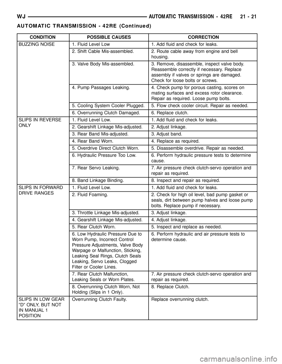
CONDITION POSSIBLE CAUSES CORRECTION
BUZZING NOISE 1. Fluid Level Low 1. Add fluid and check for leaks.
2. Shift Cable Mis-assembled. 2. Route cable away from engine and bell
housing.
3. Valve Body Mis-assembled. 3. Remove, disassemble, inspect valve body.
Reassemble correctly if necessary. Replace
assembly if valves or springs are damaged.
Check for loose bolts or screws.
4. Pump Passages Leaking. 4. Check pump for porous casting, scores on
mating surfaces and excess rotor clearance.
Repair as required. Loose pump bolts.
5. Cooling System Cooler Plugged. 5. Flow check cooler circuit. Repair as needed.
6. Overrunning Clutch Damaged. 6. Replace clutch.
SLIPS IN REVERSE
ONLY1. Fluid Level Low. 1. Add fluid and check for leaks.
2. Gearshift Linkage Mis-adjusted. 2. Adjust linkage.
3. Rear Band Mis-adjusted. 3. Adjust band.
4. Rear Band Worn. 4. Replace as required.
5. Overdrive Direct Clutch Worn. 5. Disassemble overdrive. Repair as needed.
6. Hydraulic Pressure Too Low. 6. Perform hydraulic pressure tests to determine
cause.
7. Rear Servo Leaking. 7. Air pressure check clutch-servo operation and
repair as required.
8. Band Linkage Binding. 8. Inspect and repair as required.
SLIPS IN FORWARD
DRIVE RANGES1. Fluid Level Low. 1. Add fluid and check for leaks.
2. Fluid Foaming. 2. Check for high oil level, bad pump gasket or
seals, dirt between pump halves and loose pump
bolts. Replace pump if necessary.
3. Throttle Linkage Mis-adjusted. 3. Adjust linkage.
4. Gearshift Linkage Mis-adjusted. 4. Adjust linkage.
5. Rear Clutch Worn. 5. Inspect and replace as needed.
6. Low Hydraulic Pressure Due to
Worn Pump, Incorrect Control
Pressure Adjustments, Valve Body
Warpage or Malfunction, Sticking,
Leaking Seal Rings, Clutch Seals
Leaking, Servo Leaks, Clogged
Filter or Cooler Lines.6. Perform hydraulic and air pressure tests to
determine cause.
7. Rear Clutch Malfunction,
Leaking Seals or Worn Plates.7. Air pressure check clutch-servo operation and
repair as required.
8. Overrunning Clutch Worn, Not
Holding (Slips in 1 Only).8. Replace Clutch.
SLIPS IN LOW GEAR
9D9ONLY, BUT NOT
IN MANUAL 1
POSITIONOverrunning Clutch Faulty. Replace overrunning clutch.
WJAUTOMATIC TRANSMISSION - 42RE 21 - 21
AUTOMATIC TRANSMISSION - 42RE (Continued)
Page 1541 of 2199
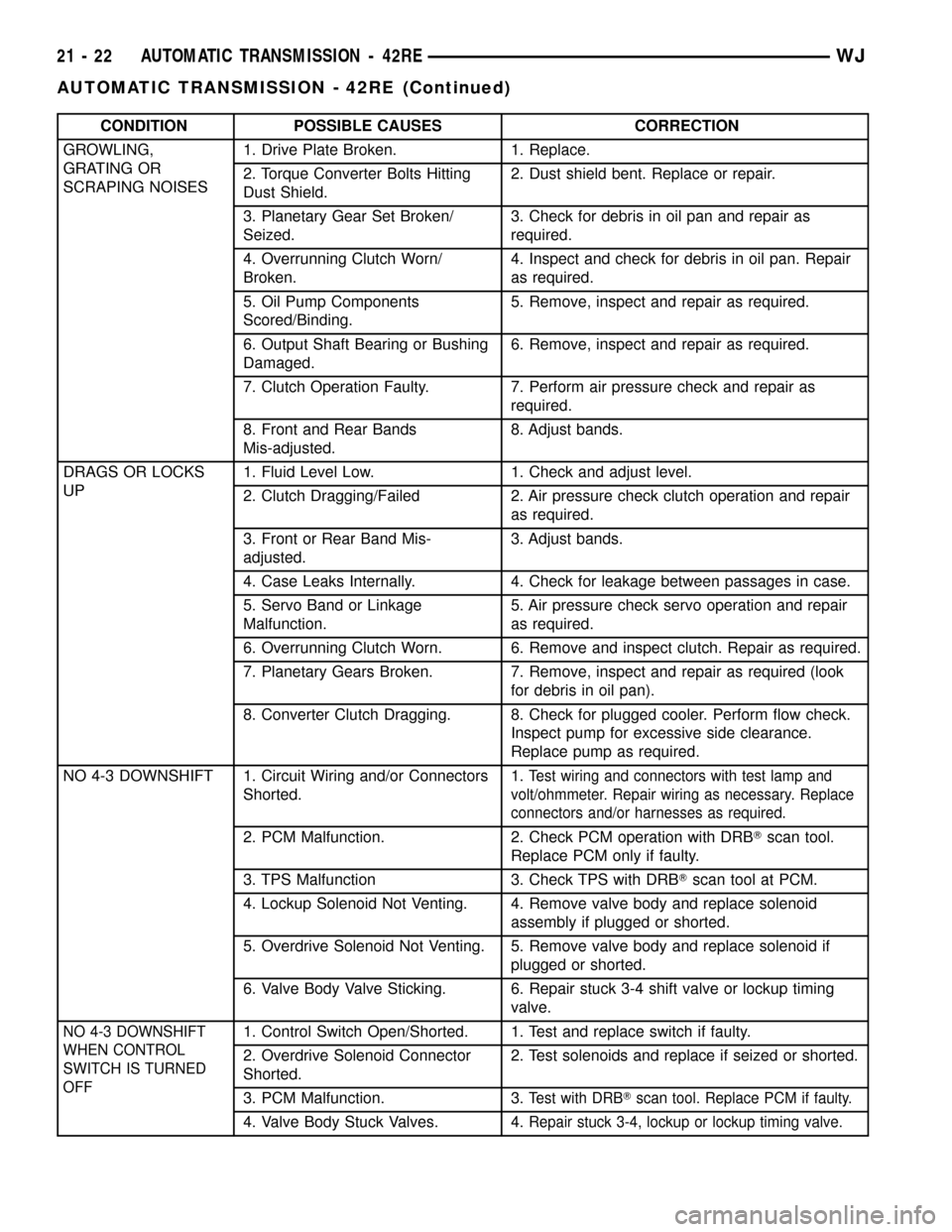
CONDITION POSSIBLE CAUSES CORRECTION
GROWLING,
GRATING OR
SCRAPING NOISES1. Drive Plate Broken. 1. Replace.
2. Torque Converter Bolts Hitting
Dust Shield.2. Dust shield bent. Replace or repair.
3. Planetary Gear Set Broken/
Seized.3. Check for debris in oil pan and repair as
required.
4. Overrunning Clutch Worn/
Broken.4. Inspect and check for debris in oil pan. Repair
as required.
5. Oil Pump Components
Scored/Binding.5. Remove, inspect and repair as required.
6. Output Shaft Bearing or Bushing
Damaged.6. Remove, inspect and repair as required.
7. Clutch Operation Faulty. 7. Perform air pressure check and repair as
required.
8. Front and Rear Bands
Mis-adjusted.8. Adjust bands.
DRAGS OR LOCKS
UP1. Fluid Level Low. 1. Check and adjust level.
2. Clutch Dragging/Failed 2. Air pressure check clutch operation and repair
as required.
3. Front or Rear Band Mis-
adjusted.3. Adjust bands.
4. Case Leaks Internally. 4. Check for leakage between passages in case.
5. Servo Band or Linkage
Malfunction.5. Air pressure check servo operation and repair
as required.
6. Overrunning Clutch Worn. 6. Remove and inspect clutch. Repair as required.
7. Planetary Gears Broken. 7. Remove, inspect and repair as required (look
for debris in oil pan).
8. Converter Clutch Dragging. 8. Check for plugged cooler. Perform flow check.
Inspect pump for excessive side clearance.
Replace pump as required.
NO 4-3 DOWNSHIFT 1. Circuit Wiring and/or Connectors
Shorted.1.
Test wiring and connectors with test lamp and
volt/ohmmeter. Repair wiring as necessary. Replace
connectors and/or harnesses as required.
2. PCM Malfunction. 2. Check PCM operation with DRBTscan tool.
Replace PCM only if faulty.
3. TPS Malfunction 3. Check TPS with DRBTscan tool at PCM.
4. Lockup Solenoid Not Venting. 4. Remove valve body and replace solenoid
assembly if plugged or shorted.
5. Overdrive Solenoid Not Venting. 5. Remove valve body and replace solenoid if
plugged or shorted.
6. Valve Body Valve Sticking. 6. Repair stuck 3-4 shift valve or lockup timing
valve.
NO 4-3 DOWNSHIFT
WHEN CONTROL
SWITCH IS TURNED
OFF1. Control Switch Open/Shorted. 1. Test and replace switch if faulty.
2. Overdrive Solenoid Connector
Shorted.2. Test solenoids and replace if seized or shorted.
3. PCM Malfunction. 3.
Test with DRBTscan tool. Replace PCM if faulty.
4. Valve Body Stuck Valves. 4.Repair stuck 3-4, lockup or lockup timing valve.
21 - 22 AUTOMATIC TRANSMISSION - 42REWJ
AUTOMATIC TRANSMISSION - 42RE (Continued)
Page 1542 of 2199
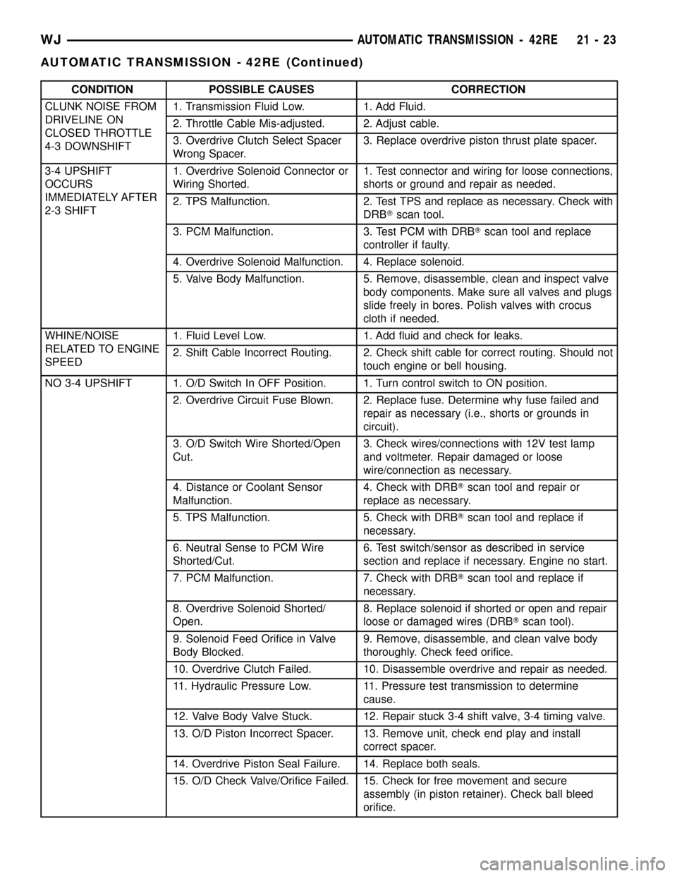
CONDITION POSSIBLE CAUSES CORRECTION
CLUNK NOISE FROM
DRIVELINE ON
CLOSED THROTTLE
4-3 DOWNSHIFT1. Transmission Fluid Low. 1. Add Fluid.
2. Throttle Cable Mis-adjusted. 2. Adjust cable.
3. Overdrive Clutch Select Spacer
Wrong Spacer.3. Replace overdrive piston thrust plate spacer.
3-4 UPSHIFT
OCCURS
IMMEDIATELY AFTER
2-3 SHIFT1. Overdrive Solenoid Connector or
Wiring Shorted.1.
Test connector and wiring for loose connections,
shorts or ground and repair as needed.
2. TPS Malfunction. 2. Test TPS and replace as necessary. Check with
DRBTscan tool.
3. PCM Malfunction. 3. Test PCM with DRBTscan tool and replace
controller if faulty.
4. Overdrive Solenoid Malfunction. 4. Replace solenoid.
5. Valve Body Malfunction. 5. Remove, disassemble, clean and inspect valve
body components. Make sure all valves and plugs
slide freely in bores. Polish valves with crocus
cloth if needed.
WHINE/NOISE
RELATED TO ENGINE
SPEED1. Fluid Level Low. 1. Add fluid and check for leaks.
2. Shift Cable Incorrect Routing. 2. Check shift cable for correct routing. Should not
touch engine or bell housing.
NO 3-4 UPSHIFT 1. O/D Switch In OFF Position. 1. Turn control switch to ON position.
2. Overdrive Circuit Fuse Blown. 2. Replace fuse. Determine why fuse failed and
repair as necessary (i.e., shorts or grounds in
circuit).
3. O/D Switch Wire Shorted/Open
Cut.3. Check wires/connections with 12V test lamp
and voltmeter. Repair damaged or loose
wire/connection as necessary.
4. Distance or Coolant Sensor
Malfunction.4. Check with DRBTscan tool and repair or
replace as necessary.
5. TPS Malfunction. 5. Check with DRBTscan tool and replace if
necessary.
6. Neutral Sense to PCM Wire
Shorted/Cut.6. Test switch/sensor as described in service
section and replace if necessary. Engine no start.
7. PCM Malfunction. 7. Check with DRBTscan tool and replace if
necessary.
8. Overdrive Solenoid Shorted/
Open.8. Replace solenoid if shorted or open and repair
loose or damaged wires (DRBTscan tool).
9. Solenoid Feed Orifice in Valve
Body Blocked.9. Remove, disassemble, and clean valve body
thoroughly. Check feed orifice.
10. Overdrive Clutch Failed. 10. Disassemble overdrive and repair as needed.
11. Hydraulic Pressure Low. 11. Pressure test transmission to determine
cause.
12. Valve Body Valve Stuck. 12. Repair stuck 3-4 shift valve, 3-4 timing valve.
13. O/D Piston Incorrect Spacer. 13. Remove unit, check end play and install
correct spacer.
14. Overdrive Piston Seal Failure. 14. Replace both seals.
15. O/D Check Valve/Orifice Failed. 15. Check for free movement and secure
assembly (in piston retainer). Check ball bleed
orifice.
WJAUTOMATIC TRANSMISSION - 42RE 21 - 23
AUTOMATIC TRANSMISSION - 42RE (Continued)
Page 1543 of 2199
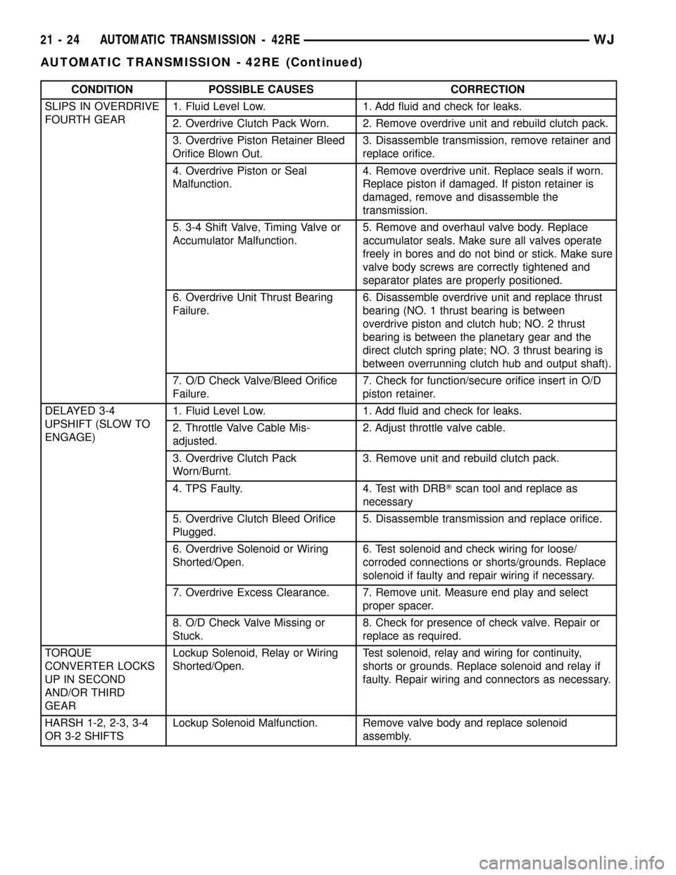
CONDITION POSSIBLE CAUSES CORRECTION
SLIPS IN OVERDRIVE
FOURTH GEAR1. Fluid Level Low. 1. Add fluid and check for leaks.
2. Overdrive Clutch Pack Worn. 2. Remove overdrive unit and rebuild clutch pack.
3. Overdrive Piston Retainer Bleed
Orifice Blown Out.3. Disassemble transmission, remove retainer and
replace orifice.
4. Overdrive Piston or Seal
Malfunction.4. Remove overdrive unit. Replace seals if worn.
Replace piston if damaged. If piston retainer is
damaged, remove and disassemble the
transmission.
5. 3-4 Shift Valve, Timing Valve or
Accumulator Malfunction.5. Remove and overhaul valve body. Replace
accumulator seals. Make sure all valves operate
freely in bores and do not bind or stick. Make sure
valve body screws are correctly tightened and
separator plates are properly positioned.
6. Overdrive Unit Thrust Bearing
Failure.6. Disassemble overdrive unit and replace thrust
bearing (NO. 1 thrust bearing is between
overdrive piston and clutch hub; NO. 2 thrust
bearing is between the planetary gear and the
direct clutch spring plate; NO. 3 thrust bearing is
between overrunning clutch hub and output shaft).
7. O/D Check Valve/Bleed Orifice
Failure.7. Check for function/secure orifice insert in O/D
piston retainer.
DELAYED 3-4
UPSHIFT (SLOW TO
ENGAGE)1. Fluid Level Low. 1. Add fluid and check for leaks.
2. Throttle Valve Cable Mis-
adjusted.2. Adjust throttle valve cable.
3. Overdrive Clutch Pack
Worn/Burnt.3. Remove unit and rebuild clutch pack.
4. TPS Faulty. 4. Test with DRBTscan tool and replace as
necessary
5. Overdrive Clutch Bleed Orifice
Plugged.5. Disassemble transmission and replace orifice.
6. Overdrive Solenoid or Wiring
Shorted/Open.6. Test solenoid and check wiring for loose/
corroded connections or shorts/grounds. Replace
solenoid if faulty and repair wiring if necessary.
7. Overdrive Excess Clearance. 7. Remove unit. Measure end play and select
proper spacer.
8. O/D Check Valve Missing or
Stuck.8. Check for presence of check valve. Repair or
replace as required.
TORQUE
CONVERTER LOCKS
UP IN SECOND
AND/OR THIRD
GEARLockup Solenoid, Relay or Wiring
Shorted/Open.Test solenoid, relay and wiring for continuity,
shorts or grounds. Replace solenoid and relay if
faulty. Repair wiring and connectors as necessary.
HARSH 1-2, 2-3, 3-4
OR 3-2 SHIFTSLockup Solenoid Malfunction. Remove valve body and replace solenoid
assembly.
21 - 24 AUTOMATIC TRANSMISSION - 42REWJ
AUTOMATIC TRANSMISSION - 42RE (Continued)
Page 1553 of 2199

(36) Compress rear servo spring retainer about
1/16 inch with Valve Spring Compressor C-3422-B
(Fig. 38).
(37) Remove rear servo spring retainer snap-ring.
Then remove compressor tools and remove rear servo
spring and piston.
(38) Inspect transmission components.
NOTE: To Service the overrunning clutch cam or
overdrive piston retainer, refer to the Overrunning
Clutch Cam service procedure in this section.
CLEANING
Clean the case in a solvent tank. Flush the case
bores and fluid passages thoroughly with solvent.
Dry the case and all fluid passages with compressed
air. Be sure all solvent is removed from the case and
that all fluid passages are clear.
NOTE: Do not use shop towels or rags to dry the
case (or any other transmission component) unless
they are made from lint-free materials. Lint will stick
to case surfaces and transmission components and
circulate throughout the transmission after assem-
bly. A sufficient quantity of lint can block fluid pas-
sages and interfere with valve body operation.Lubricate transmission parts with MopartATF +4,
type 9602, transmission fluid during overhaul and
assembly. Use petroleum jelly, MopartDoor Ease, or
Ru-GlydeŸ to prelubricate seals, O-rings, and thrust
washers. Petroleum jelly can also be used to hold
parts in place during reassembly.
INSPECTION
Inspect the case for cracks, porous spots, worn
bores, or damaged threads. Damaged threads can be
repaired with Helicoil thread inserts. However, the
case will have to be replaced if it exhibits any type of
damage or wear.
Lubricate the front band adjusting screw threads
with petroleum jelly and thread the screw part-way
into the case. Be sure the screw turns freely.
Inspect the transmission bushings during overhaul.
Bushing condition is important as worn, scored bush-
ings contribute to low pressures, clutch slip and
accelerated wear of other components. However, do
not replace bushings as a matter of course. Replace
bushings only when they are actually worn, or
scored.
Use recommended tools to replace bushings. The
tools are sized and designed to remove, install, and
seat bushings correctly. The bushing replacement
tools are included in Bushing Tool Set C-3887-B.
Pre-sized service bushings are available for
replacement purposes. Only the sun gear bushings
are not serviced.
The use of crocus cloth is permissible where neces-
sary, providing it is used carefully. When used on
shafts, or valves, use extreme care to avoid rounding
off sharp edges. Sharp edges are vital as they pre-
vent foreign matter from getting between the valve
and valve bore.
Do not reuse oil seals, gaskets, seal rings, or
O-rings during overhaul. Replace these parts as a
matter of course. Also do not reuse snap rings or
E-clips that are bent or distorted. Replace these parts
as well.
ASSEMBLY
Do not allow dirt, grease, or foreign material to
enter the case or transmission components during
assembly. Keep the transmission case and compo-
nents clean. Also make sure the tools and workbench
area used for assembly operations are equally clean.
Shop towels used for wiping off tools and hands
must be made fromlint freematerial. Lint will stick
to transmission parts and could interfere with valve
operation, or even restrict fluid passages.
Lubricate the transmission components with
Moparttransmission fluid during reassembly. Use
MopartDoor Ease, or Ru-GlydeŸ on seals and
O-rings to ease installation.
Fig. 38 Compressing Rear Servo Spring
1 - FRONT SERVO SNAP-RING
2 - REAR SERVO SNAP-RING
3 - SPECIAL TOOL
21 - 34 AUTOMATIC TRANSMISSION - 42REWJ
AUTOMATIC TRANSMISSION - 42RE (Continued)