dash JEEP GRAND CHEROKEE 2002 WJ / 2.G Service Manual
[x] Cancel search | Manufacturer: JEEP, Model Year: 2002, Model line: GRAND CHEROKEE, Model: JEEP GRAND CHEROKEE 2002 WJ / 2.GPages: 2199, PDF Size: 76.01 MB
Page 1072 of 2199
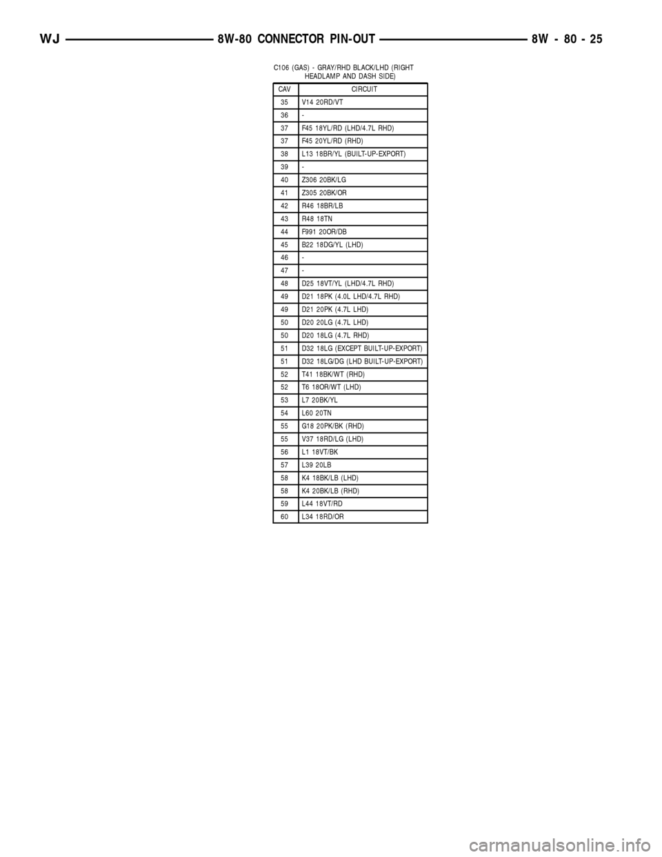
C106 (GAS) - GRAY/RHD BLACK/LHD (RIGHT
HEADLAMP AND DASH SIDE)
CAV CIRCUIT
35 V14 20RD/VT
36 -
37 F45 18YL/RD (LHD/4.7L RHD)
37 F45 20YL/RD (RHD)
38 L13 18BR/YL (BUILT-UP-EXPORT)
39 -
40 Z306 20BK/LG
41 Z305 20BK/OR
42 R46 18BR/LB
43 R48 18TN
44 F991 20OR/DB
45 B22 18DG/YL (LHD)
46 -
47 -
48 D25 18VT/YL (LHD/4.7L RHD)
49 D21 18PK (4.0L LHD/4.7L RHD)
49 D21 20PK (4.7L LHD)
50 D20 20LG (4.7L LHD)
50 D20 18LG (4.7L RHD)
51 D32 18LG (EXCEPT BUILT-UP-EXPORT)
51 D32 18LG/DG (LHD BUILT-UP-EXPORT)
52 T41 18BK/WT (RHD)
52 T6 18OR/WT (LHD)
53 L7 20BK/YL
54 L60 20TN
55 G18 20PK/BK (RHD)
55 V37 18RD/LG (LHD)
56 L1 18VT/BK
57 L39 20LB
58 K4 18BK/LB (LHD)
58 K4 20BK/LB (RHD)
59 L44 18VT/RD
60 L34 18RD/OR
WJ8W-80 CONNECTOR PIN-OUT 8W - 80 - 25
Page 1075 of 2199
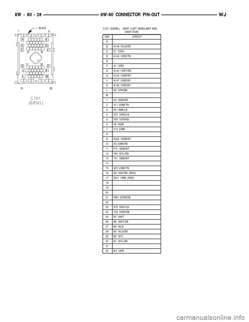
C107 (DIESEL) - GRAY (LEFT HEADLAMP AND
DASH SIDE)
CAV CIRCUIT
A-
B A148 16LG/RD
C C1 12DG
D A149 12RD/TN
E-
F A1 12RD
G A145 10WT/RD
H A146 10OR/WT
J A147 10RD/GY
K A148 10PK/WT
L A2 12PK/BK
M-
1 X2 18DG/RD
2 V11 20BK/TN
3 K4 18BK/LB
4 V37 18RD/LG
5 V55 16TN/RD
6 V6 16DB
7 V10 20BR
8-
9 K226 18DB/WT
10 X3 20BK/RD
11 F15 18DB/WT
12 F45 18YL/RD
13 T41 18BK/WT
14 -
15 G70 20BR/TN
16 G9 18GY/BK (RHD)
17 Z231 18BK (RHD)
18 -
19 -
20 -
21 F991 20OR/DB
22 -
23 X75 18GY/LB
24 Y42 18OR/DB
25 B7 18WT
26 B6 18WT/DB
27 B4 18LG
28 B3 18LG/DB
29 B2 18YL
30 B1 18YL/DB
31 -
32 M1 18PK
8W - 80 - 28 8W-80 CONNECTOR PIN-OUTWJ
Page 1076 of 2199
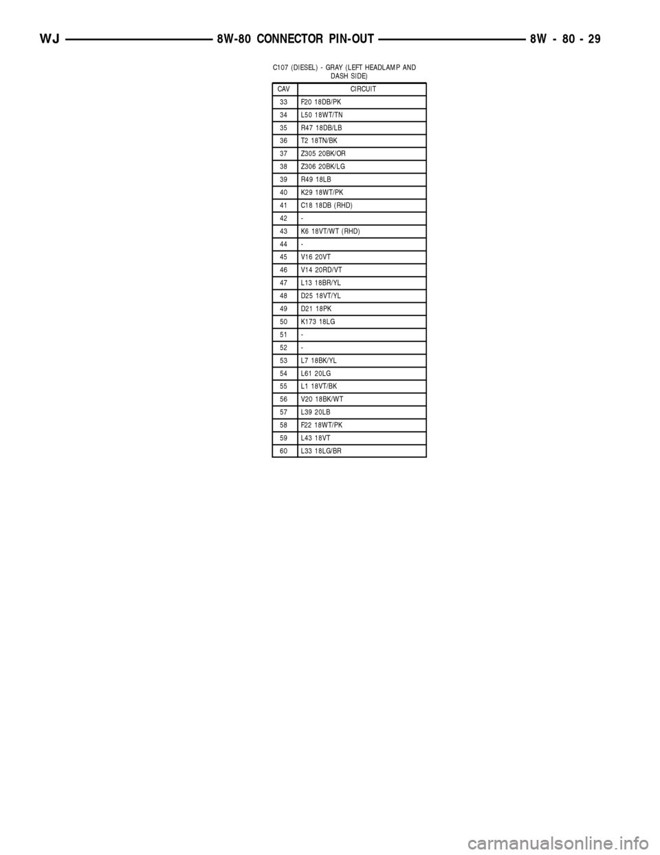
C107 (DIESEL) - GRAY (LEFT HEADLAMP AND
DASH SIDE)
CAV CIRCUIT
33 F20 18DB/PK
34 L50 18WT/TN
35 R47 18DB/LB
36 T2 18TN/BK
37 Z305 20BK/OR
38 Z306 20BK/LG
39 R49 18LB
40 K29 18WT/PK
41 C18 18DB (RHD)
42 -
43 K6 18VT/WT (RHD)
44 -
45 V16 20VT
46 V14 20RD/VT
47 L13 18BR/YL
48 D25 18VT/YL
49 D21 18PK
50 K173 18LG
51 -
52 -
53 L7 18BK/YL
54 L61 20LG
55 L1 18VT/BK
56 V20 18BK/WT
57 L39 20LB
58 F22 18WT/PK
59 L43 18VT
60 L33 18LG/BR
WJ8W-80 CONNECTOR PIN-OUT 8W - 80 - 29
Page 1079 of 2199
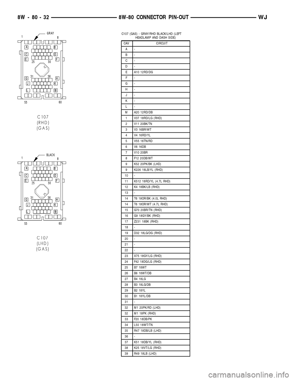
C107 (GAS) - GRAY/RHD BLACK/LHD (LEFT
HEADLAMP AND DASH SIDE)
CAV CIRCUIT
A-
B-
C-
D-
E A10 12RD/DG
F-
G-
H-
J-
K-
L-
M A20 12RD/DB
1 V37 18RD/LG (RHD)
2 V11 20BK/TN
3 V3 16BR/WT
4 V4 16RD/YL
5 V55 16TN/RD
6 V6 16DB
7 V10 20BR
8 F12 20DB/WT
9 K52 20PK/BK (LHD)
9 K226 18LB/YL (RHD)
10 -
11 K512 18RD/YL (4.7L RHD)
12 K4 18BK/LB (RHD)
13 -
14 T6 18OR/BK (4.0L RHD)
14 T6 18OR/WT (4.7L RHD)
15 G70 20BR/TN (RHD)
16 G9 18GY/BK (RHD)
17 Z231 18BK (RHD)
18 -
19 D32 18LG/DG (RHD)
20 -
21 -
22 -
23 X75 18GY/LG (RHD)
24 F42 18DG/LG (RHD)
25 B7 18WT
26 B6 18WT/DB
27 B4 18LG
28 B3 18LG/DB
29 B2 18YL
30 B1 18YL/DB
31 -
32 M1 20PK/RD (LHD)
32 M1 18PK (RHD)
33 F20 18DB/PK
34 L50 18WT/TN
35 R47 18DB/LB (LHD)
36 -
37 K51 18DB/YL (RHD)
38 K25 18VT/LG (RHD)
39 R49 18LB (LHD)
8W - 80 - 32 8W-80 CONNECTOR PIN-OUTWJ
Page 1080 of 2199
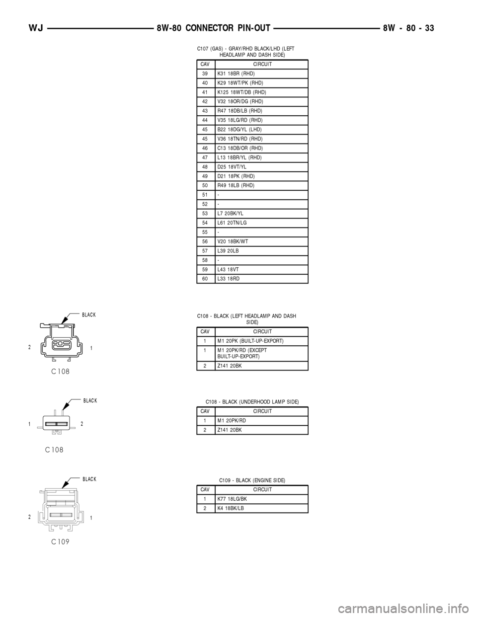
C107 (GAS) - GRAY/RHD BLACK/LHD (LEFT
HEADLAMP AND DASH SIDE)
CAV CIRCUIT
39 K31 18BR (RHD)
40 K29 18WT/PK (RHD)
41 K125 18WT/DB (RHD)
42 V32 18OR/DG (RHD)
43 R47 18DB/LB (RHD)
44 V35 18LG/RD (RHD)
45 B22 18DG/YL (LHD)
45 V36 18TN/RD (RHD)
46 C13 18DB/OR (RHD)
47 L13 18BR/YL (RHD)
48 D25 18VT/YL
49 D21 18PK (RHD)
50 R49 18LB (RHD)
51 -
52 -
53 L7 20BK/YL
54 L61 20TN/LG
55 -
56 V20 18BK/WT
57 L39 20LB
58 -
59 L43 18VT
60 L33 18RD
C108 - BLACK (LEFT HEADLAMP AND DASH
SIDE)
CAV CIRCUIT
1 M1 20PK (BUILT-UP-EXPORT)
1 M1 20PK/RD (EXCEPT
BUILT-UP-EXPORT)
2 Z141 20BK
C108 - BLACK (UNDERHOOD LAMP SIDE)
CAV CIRCUIT
1 M1 20PK/RD
2 Z141 20BK
C109 - BLACK (ENGINE SIDE)
CAV CIRCUIT
1 K77 18LG/BK
2 K4 18BK/LB
WJ8W-80 CONNECTOR PIN-OUT 8W - 80 - 33
Page 1081 of 2199
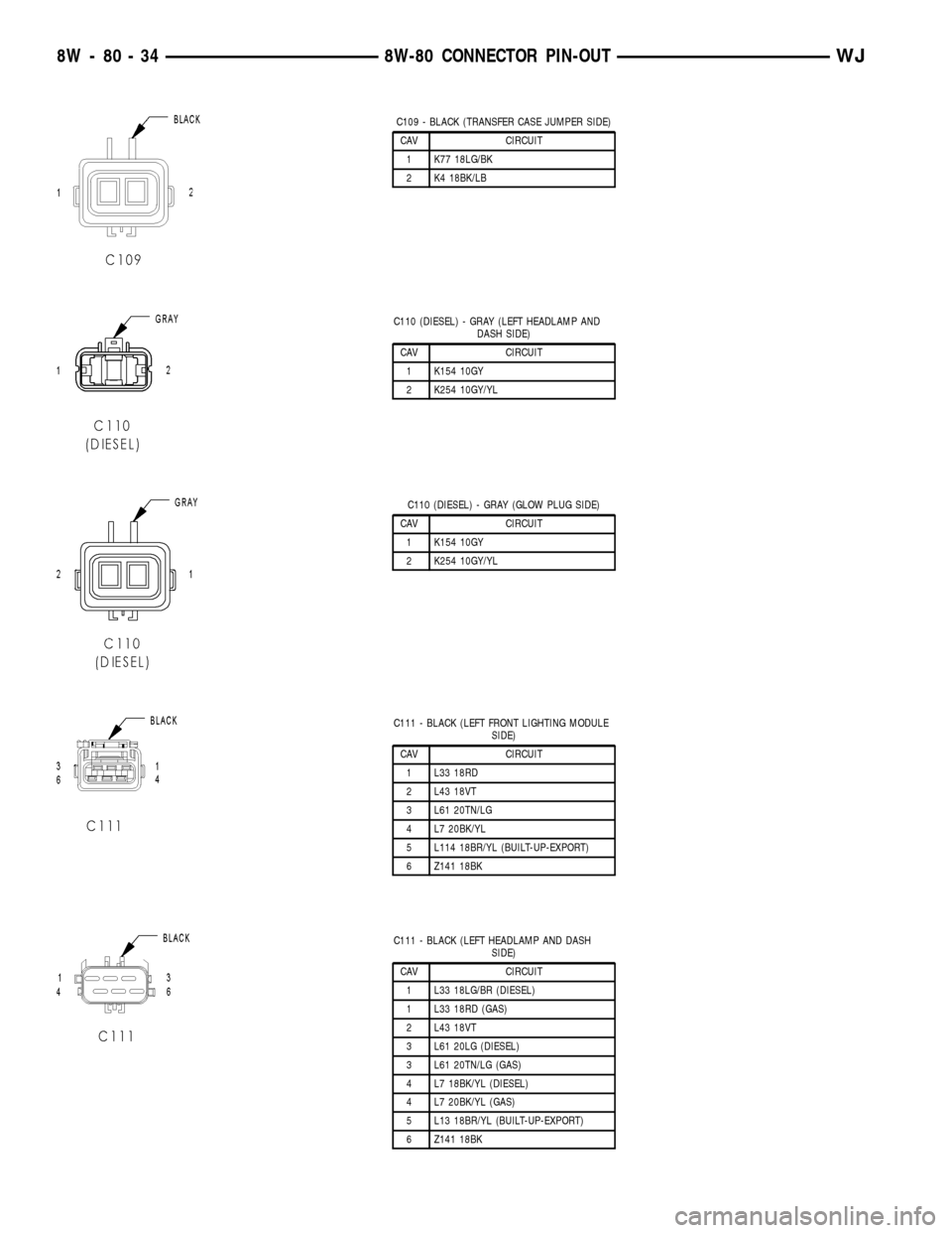
C109 - BLACK (TRANSFER CASE JUMPER SIDE)
CAV CIRCUIT
1 K77 18LG/BK
2 K4 18BK/LB
C110 (DIESEL) - GRAY (LEFT HEADLAMP AND
DASH SIDE)
CAV CIRCUIT
1 K154 10GY
2 K254 10GY/YL
C110 (DIESEL) - GRAY (GLOW PLUG SIDE)
CAV CIRCUIT
1 K154 10GY
2 K254 10GY/YL
C111 - BLACK (LEFT FRONT LIGHTING MODULE
SIDE)
CAV CIRCUIT
1 L33 18RD
2 L43 18VT
3 L61 20TN/LG
4 L7 20BK/YL
5 L114 18BR/YL (BUILT-UP-EXPORT)
6 Z141 18BK
C111 - BLACK (LEFT HEADLAMP AND DASH
SIDE)
CAV CIRCUIT
1 L33 18LG/BR (DIESEL)
1 L33 18RD (GAS)
2 L43 18VT
3 L61 20LG (DIESEL)
3 L61 20TN/LG (GAS)
4 L7 18BK/YL (DIESEL)
4 L7 20BK/YL (GAS)
5 L13 18BR/YL (BUILT-UP-EXPORT)
6 Z141 18BK
8W - 80 - 34 8W-80 CONNECTOR PIN-OUTWJ
Page 1082 of 2199
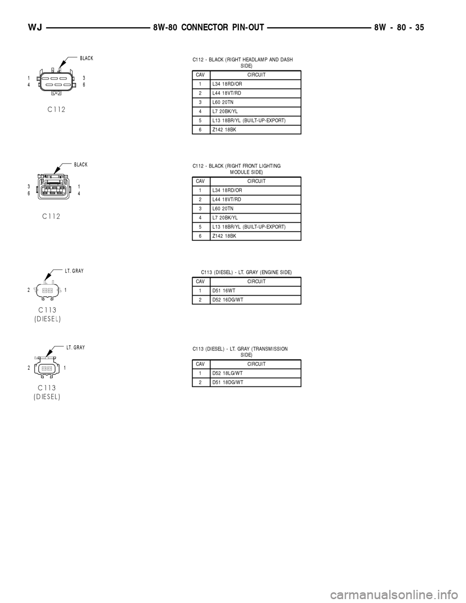
C112 - BLACK (RIGHT HEADLAMP AND DASH
SIDE)
CAV CIRCUIT
1 L34 18RD/OR
2 L44 18VT/RD
3 L60 20TN
4 L7 20BK/YL
5 L13 18BR/YL (BUILT-UP-EXPORT)
6 Z142 18BK
C112 - BLACK (RIGHT FRONT LIGHTING
MODULE SIDE)
CAV CIRCUIT
1 L34 18RD/OR
2 L44 18VT/RD
3 L60 20TN
4 L7 20BK/YL
5 L13 18BR/YL (BUILT-UP-EXPORT)
6 Z142 18BK
C113 (DIESEL) - LT. GRAY (ENGINE SIDE)
CAV CIRCUIT
1 D51 16WT
2 D52 16DG/WT
C113 (DIESEL) - LT. GRAY (TRANSMISSION
SIDE)
CAV CIRCUIT
1 D52 18LG/WT
2 D51 18DG/WT
WJ8W-80 CONNECTOR PIN-OUT 8W - 80 - 35
Page 1230 of 2199
JUNCTION BLOCK
DESCRIPTION
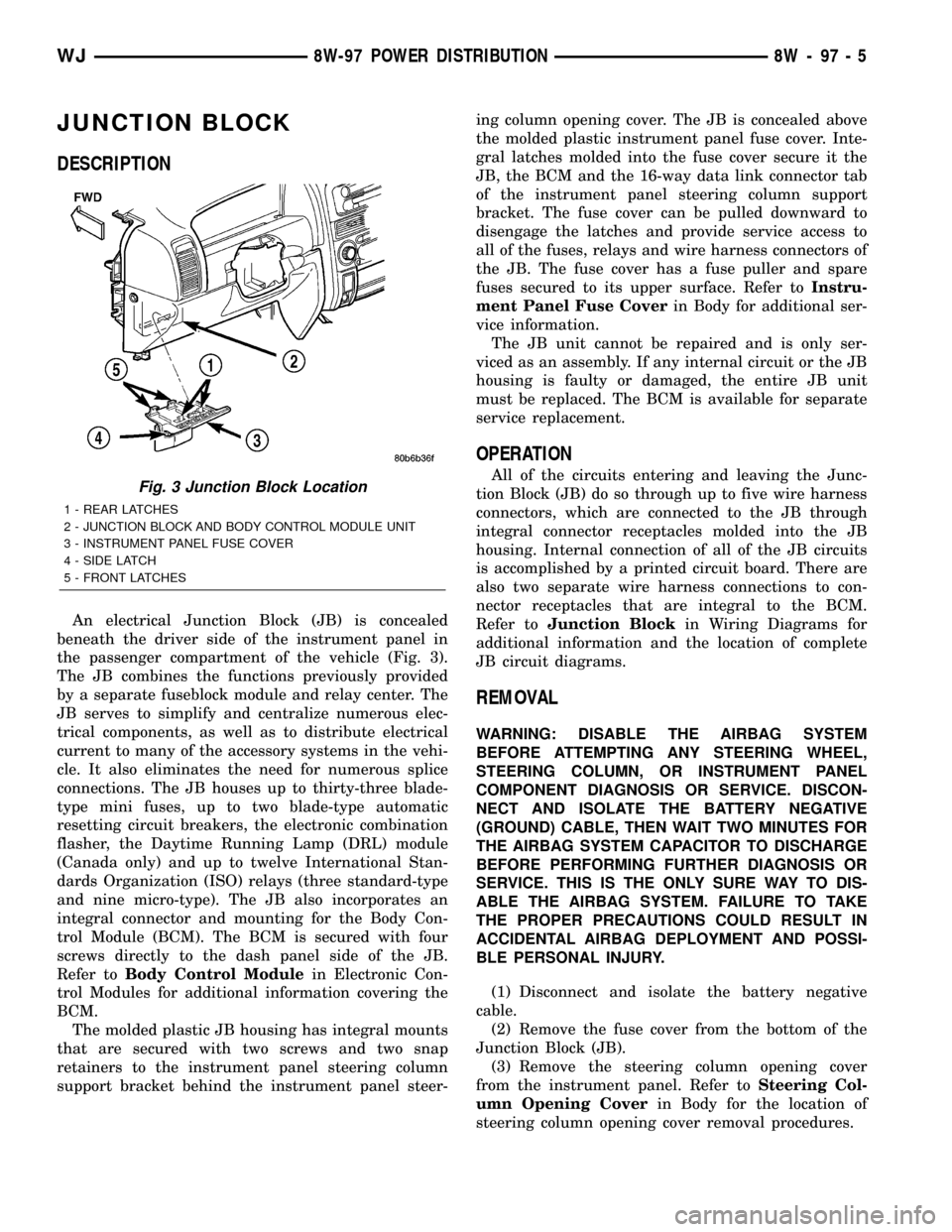
An electrical Junction Block (JB) is concealed
beneath the driver side of the instrument panel in
the passenger compartment of the vehicle (Fig. 3).
The JB combines the functions previously provided
by a separate fuseblock module and relay center. The
JB serves to simplify and centralize numerous elec-
trical components, as well as to distribute electrical
current to many of the accessory systems in the vehi-
cle. It also eliminates the need for numerous splice
connections. The JB houses up to thirty-three blade-
type mini fuses, up to two blade-type automatic
resetting circuit breakers, the electronic combination
flasher, the Daytime Running Lamp (DRL) module
(Canada only) and up to twelve International Stan-
dards Organization (ISO) relays (three standard-type
and nine micro-type). The JB also incorporates an
integral connector and mounting for the Body Con-
trol Module (BCM). The BCM is secured with four
screws directly to the dash panel side of the JB.
Refer toBody Control Modulein Electronic Con-
trol Modules for additional information covering the
BCM.
The molded plastic JB housing has integral mounts
that are secured with two screws and two snap
retainers to the instrument panel steering column
support bracket behind the instrument panel steer-ing column opening cover. The JB is concealed above
the molded plastic instrument panel fuse cover. Inte-
gral latches molded into the fuse cover secure it the
JB, the BCM and the 16-way data link connector tab
of the instrument panel steering column support
bracket. The fuse cover can be pulled downward to
disengage the latches and provide service access to
all of the fuses, relays and wire harness connectors of
the JB. The fuse cover has a fuse puller and spare
fuses secured to its upper surface. Refer toInstru-
ment Panel Fuse Coverin Body for additional ser-
vice information.
The JB unit cannot be repaired and is only ser-
viced as an assembly. If any internal circuit or the JB
housing is faulty or damaged, the entire JB unit
must be replaced. The BCM is available for separate
service replacement.
OPERATION
All of the circuits entering and leaving the Junc-
tion Block (JB) do so through up to five wire harness
connectors, which are connected to the JB through
integral connector receptacles molded into the JB
housing. Internal connection of all of the JB circuits
is accomplished by a printed circuit board. There are
also two separate wire harness connections to con-
nector receptacles that are integral to the BCM.
Refer toJunction Blockin Wiring Diagrams for
additional information and the location of complete
JB circuit diagrams.
REMOVAL
WARNING: DISABLE THE AIRBAG SYSTEM
BEFORE ATTEMPTING ANY STEERING WHEEL,
STEERING COLUMN, OR INSTRUMENT PANEL
COMPONENT DIAGNOSIS OR SERVICE. DISCON-
NECT AND ISOLATE THE BATTERY NEGATIVE
(GROUND) CABLE, THEN WAIT TWO MINUTES FOR
THE AIRBAG SYSTEM CAPACITOR TO DISCHARGE
BEFORE PERFORMING FURTHER DIAGNOSIS OR
SERVICE. THIS IS THE ONLY SURE WAY TO DIS-
ABLE THE AIRBAG SYSTEM. FAILURE TO TAKE
THE PROPER PRECAUTIONS COULD RESULT IN
ACCIDENTAL AIRBAG DEPLOYMENT AND POSSI-
BLE PERSONAL INJURY.
(1) Disconnect and isolate the battery negative
cable.
(2) Remove the fuse cover from the bottom of the
Junction Block (JB).
(3) Remove the steering column opening cover
from the instrument panel. Refer toSteering Col-
umn Opening Coverin Body for the location of
steering column opening cover removal procedures.
Fig. 3 Junction Block Location
1 - REAR LATCHES
2 - JUNCTION BLOCK AND BODY CONTROL MODULE UNIT
3 - INSTRUMENT PANEL FUSE COVER
4 - SIDE LATCH
5 - FRONT LATCHES
WJ8W-97 POWER DISTRIBUTION 8W - 97 - 5
Page 1232 of 2199
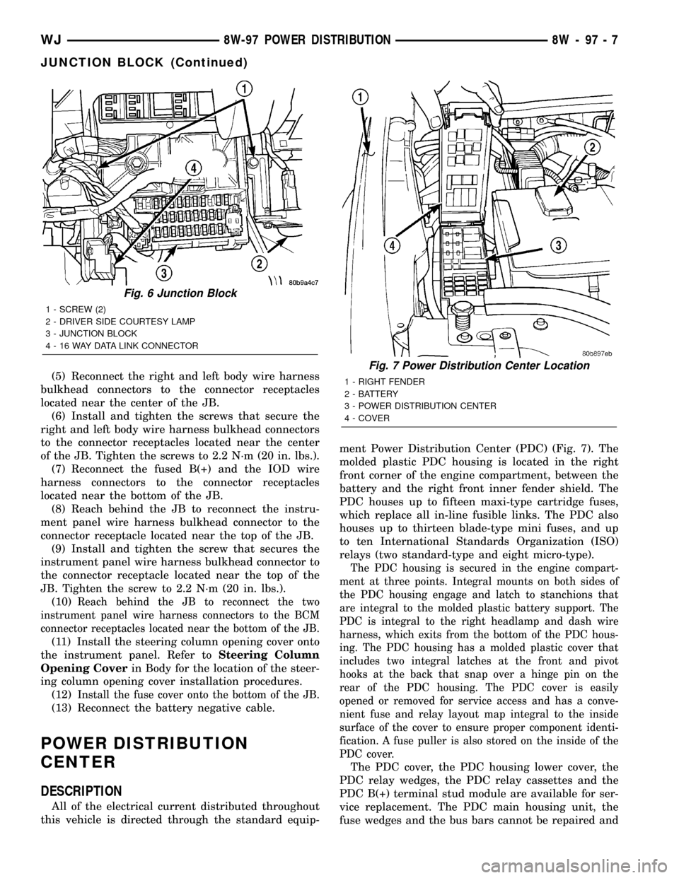
(5) Reconnect the right and left body wire harness
bulkhead connectors to the connector receptacles
located near the center of the JB.
(6) Install and tighten the screws that secure the
right and left body wire harness bulkhead connectors
to the connector receptacles located near the center
of the JB. Tighten the screws to 2.2 N´m (20 in. lbs.).
(7) Reconnect the fused B(+) and the IOD wire
harness connectors to the connector receptacles
located near the bottom of the JB.
(8) Reach behind the JB to reconnect the instru-
ment panel wire harness bulkhead connector to the
connector receptacle located near the top of the JB.
(9) Install and tighten the screw that secures the
instrument panel wire harness bulkhead connector to
the connector receptacle located near the top of the
JB. Tighten the screw to 2.2 N´m (20 in. lbs.).
(10)
Reach behind the JB to reconnect the two
instrument panel wire harness connectors to the BCM
connector receptacles located near the bottom of the JB.
(11) Install the steering column opening cover onto
the instrument panel. Refer toSteering Column
Opening Coverin Body for the location of the steer-
ing column opening cover installation procedures.
(12)
Install the fuse cover onto the bottom of the JB.
(13) Reconnect the battery negative cable.
POWER DISTRIBUTION
CENTER
DESCRIPTION
All of the electrical current distributed throughout
this vehicle is directed through the standard equip-ment Power Distribution Center (PDC) (Fig. 7). The
molded plastic PDC housing is located in the right
front corner of the engine compartment, between the
battery and the right front inner fender shield. The
PDC houses up to fifteen maxi-type cartridge fuses,
which replace all in-line fusible links. The PDC also
houses up to thirteen blade-type mini fuses, and up
to ten International Standards Organization (ISO)
relays (two standard-type and eight micro-type).
The PDC housing is secured in the engine compart-
ment at three points. Integral mounts on both sides of
the PDC housing engage and latch to stanchions that
are integral to the molded plastic battery support. The
PDC is integral to the right headlamp and dash wire
harness, which exits from the bottom of the PDC hous-
ing. The PDC housing has a molded plastic cover that
includes two integral latches at the front and pivot
hooks at the back that snap over a hinge pin on the
rear of the PDC housing. The PDC cover is easily
opened or removed for service access and has a conve-
nient fuse and relay layout map integral to the inside
surface of the cover to ensure proper component identi-
fication. A fuse puller is also stored on the inside of the
PDC cover.
The PDC cover, the PDC housing lower cover, the
PDC relay wedges, the PDC relay cassettes and the
PDC B(+) terminal stud module are available for ser-
vice replacement. The PDC main housing unit, the
fuse wedges and the bus bars cannot be repaired and
Fig. 6 Junction Block
1 - SCREW (2)
2 - DRIVER SIDE COURTESY LAMP
3 - JUNCTION BLOCK
4 - 16 WAY DATA LINK CONNECTOR
Fig. 7 Power Distribution Center Location
1 - RIGHT FENDER
2 - BATTERY
3 - POWER DISTRIBUTION CENTER
4 - COVER
WJ8W-97 POWER DISTRIBUTION 8W - 97 - 7
JUNCTION BLOCK (Continued)
Page 1233 of 2199
are only serviced as a unit with the right headlamp
and dash wire harness. If the PDC main housing
unit, fuse wedges or the bus bars are faulty or dam-
aged, the right headlamp and dash wire harness unit
must be replaced.
OPERATION
All of the current from the battery and the generator
output enters the PDC through two cables and a single
two-holed eyelet that is secured with nuts to the two
PDC B(+) terminal studs just inside the front end of the
PDC housing. The PDC cover is unlatched and opened
to access the battery and generator output connection
B(+) terminal studs, the fuses or the relays. Internal
connection of all of the PDC circuits is accomplished by
an intricate combination of hard wiring and bus bars.
Refer toPower Distribution
in Wiring Diagrams for
the location of complete PDC circuit diagrams.
REMOVAL
The Power Distribution Center (PDC) main housing
unit, the PDC fuse wedges and the PDC bus bars can-
not be repaired and are only serviced as a unit with the
right headlamp and dash wire harness. If the PDC
main housing unit, the fuse wedges or the bus bars are
faulty or damaged, the entire PDC and right headlamp
and dash wire harness unit must be replaced.
(1)Disconnect and isolate the battery negative cable.
(2) Disconnect each of the right headlamp and
dash wire harness connectors. Refer toConnector
Locationsin Wiring Diagrams for the location of
more information on the right headlamp and dash
wire harness connector locations.
(3) Remove all of the fasteners that secure each of
the right headlamp and dash wire harness ground
eyelets to the vehicle body and chassis components.
Refer toConnector Locationsin Wiring Diagrams
for the location of more information on the ground
eyelet locations.
(4) Disengage each of the retainers that secure the
right headlamp and dash wire harness to the vehicle
body and chassis components. Refer toConnector
Locationsin Wiring Diagrams for the location of
more information on the right headlamp and dash
wire harness retainer locations.
(5) Unlatch and open the PDC cover.
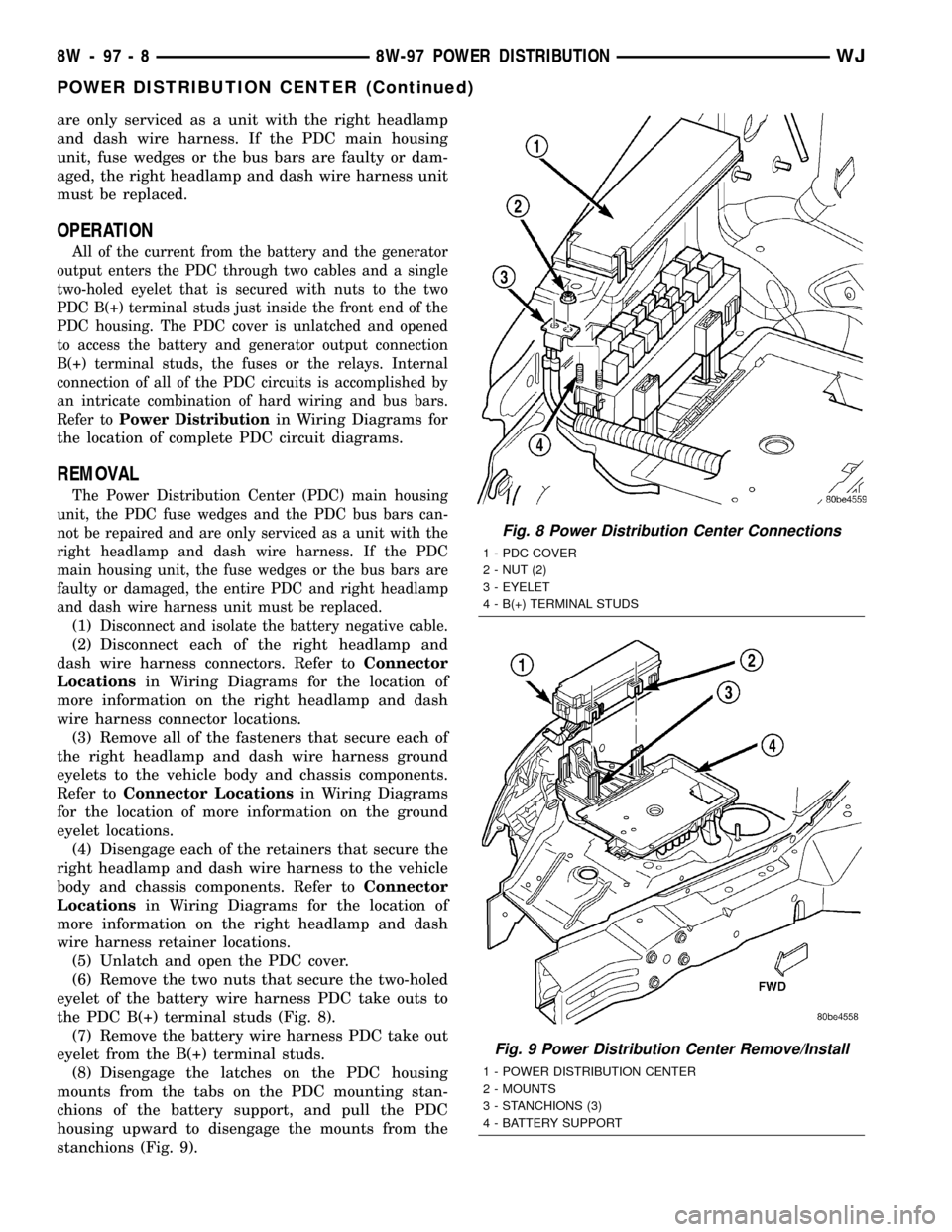
(6) Remove the two nuts that secure the two-holed
eyelet of the battery wire harness PDC take outs to
the PDC B(+) terminal studs (Fig. 8).
(7) Remove the battery wire harness PDC take out
eyelet from the B(+) terminal studs.
(8) Disengage the latches on the PDC housing
mounts from the tabs on the PDC mounting stan-
chions of the battery support, and pull the PDC
housing upward to disengage the mounts from the
stanchions (Fig. 9).
Fig. 8 Power Distribution Center Connections
1 - PDC COVER
2 - NUT (2)
3 - EYELET
4 - B(+) TERMINAL STUDS
Fig. 9 Power Distribution Center Remove/Install
1 - POWER DISTRIBUTION CENTER
2 - MOUNTS
3 - STANCHIONS (3)
4 - BATTERY SUPPORT
8W - 97 - 8 8W-97 POWER DISTRIBUTIONWJ
POWER DISTRIBUTION CENTER (Continued)