shift JEEP GRAND CHEROKEE 2002 WJ / 2.G Service Manual
[x] Cancel search | Manufacturer: JEEP, Model Year: 2002, Model line: GRAND CHEROKEE, Model: JEEP GRAND CHEROKEE 2002 WJ / 2.GPages: 2199, PDF Size: 76.01 MB
Page 1156 of 2199
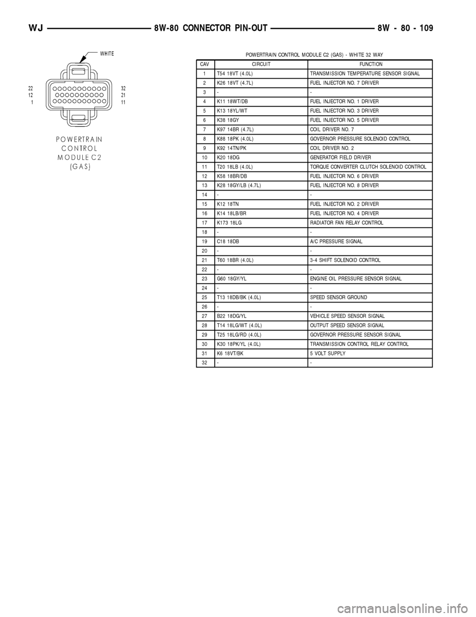
POWERTRAIN CONTROL MODULE C2 (GAS) - WHITE 32 WAY
CAV CIRCUIT FUNCTION
1 T54 18VT (4.0L) TRANSMISSION TEMPERATURE SENSOR SIGNAL
2 K26 18VT (4.7L) FUEL INJECTOR NO. 7 DRIVER
3- -
4 K11 18WT/DB FUEL INJECTOR NO. 1 DRIVER
5 K13 18YL/WT FUEL INJECTOR NO. 3 DRIVER
6 K38 18GY FUEL INJECTOR NO. 5 DRIVER
7 K97 14BR (4.7L) COIL DRIVER NO. 7
8 K88 18PK (4.0L) GOVERNOR PRESSURE SOLENOID CONTROL
9 K92 14TN/PK COIL DRIVER NO. 2
10 K20 18DG GENERATOR FIELD DRIVER
11 T20 18LB (4.0L) TORQUE CONVERTER CLUTCH SOLENOID CONTROL
12 K58 18BR/DB FUEL INJECTOR NO. 6 DRIVER
13 K28 18GY/LB (4.7L) FUEL INJECTOR NO. 8 DRIVER
14 - -
15 K12 18TN FUEL INJECTOR NO. 2 DRIVER
16 K14 18LB/BR FUEL INJECTOR NO. 4 DRIVER
17 K173 18LG RADIATOR FAN RELAY CONTROL
18 - -
19 C18 18DB A/C PRESSURE SIGNAL
20 - -
21 T60 18BR (4.0L) 3-4 SHIFT SOLENOID CONTROL
22 - -
23 G60 18GY/YL ENGINE OIL PRESSURE SENSOR SIGNAL
24 - -
25 T13 18DB/BK (4.0L) SPEED SENSOR GROUND
26 - -
27 B22 18DG/YL VEHICLE SPEED SENSOR SIGNAL
28 T14 18LG/WT (4.0L) OUTPUT SPEED SENSOR SIGNAL
29 T25 18LG/RD (4.0L) GOVERNOR PRESSURE SENSOR SIGNAL
30 K30 18PK/YL (4.0L) TRANSMISSION CONTROL RELAY CONTROL
31 K6 18VT/BK 5 VOLT SUPPLY
32 - -
WJ8W-80 CONNECTOR PIN-OUT 8W - 80 - 109
Page 1166 of 2199
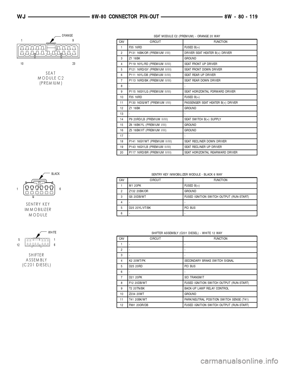
SEAT MODULE C2 (PREMIUM) - ORANGE 20 WAY
CAV CIRCUIT FUNCTION
1 F35 16RD FUSED B(+)
2 P131 16BK/OR (PREMIUM I/III) DRIVER SEAT HEATER B(+) DRIVER
3 Z1 16BK GROUND
4 P119 16YL/RD (PREMIUM II/III) SEAT FRONT UP DRIVER
5 P121 16RD/GY (PREMIUM II/III) SEAT FRONT DOWN DRIVER
6 P111 16YL/DB (PREMIUM II/III) SEAT REAR UP DRIVER
7 P113 16RD/BK (PREMIUM II/III) SEAT REAR DOWN DRIVER
8- -
9 P115 16GY/LG (PREMIUM II/III) SEAT HORIZONTAL FORWARD DRIVER
10 F35 16RD FUSED B(+)
11 P130 16DG/WT (PREMIUM I/III) PASSENGER SEAT HEATER B(+) DRIVER
12 Z1 16BK GROUND
13 - -
14 P9 20RD/LB (PREMIUM II/III) SEAT SWITCH B(+) SUPPLY
15 Z6 16BK/YL (PREMIUM I/III) GROUND
16 Z5 16BK/VT (PREMIUM I/III) GROUND
17 - -
18 P141 16GY/WT (PREMIUM II/III) SEAT RECLINER DOWN DRIVER
19 P143 16GY/LB (PREMIUM II/III) SEAT RECLINER UP DRIVER
20 P117 16RD/BR (PREMIUM II/III) SEAT HORIZONTAL REARWARD DRIVER
SENTRY KEY IMMOBILIZER MODULE - BLACK 6 WAY
CAV CIRCUIT FUNCTION
1 M1 20PK FUSED B(+)
2 Z132 20BK/OR GROUND
3 G5 20DB/WT FUSED IGNITION SWITCH OUTPUT (RUN-START)
4- -
5 D25 20YL/VT/BK PCI BUS
6- -
SHIFTER ASSEMBLY (C201 DIESEL) - WHITE 12 WAY
CAV CIRCUIT FUNCTION
1- -
2- -
3- -
4 K2 20WT/PK SECONDARY BRAKE SWITCH SIGNAL
5 D25 20RD PCI BUS
6- -
7 D21 20PK SCI TRANSMIT
8 F12 20DB/WT FUSED IGNITION SWITCH OUTPUT (RUN-START)
9 T2 20TN/BK BACK-UP LAMP RELAY CONTROL
10 Z234 20WT GROUND
11 T41 20BK/WT PARK/NEUTRAL POSITION SWITCH SENSE (T41)
12 F991 20OR/DB FUSED IGNITION SWITCH OUTPUT (RUN-START)
WJ8W-80 CONNECTOR PIN-OUT 8W - 80 - 119
Page 1167 of 2199
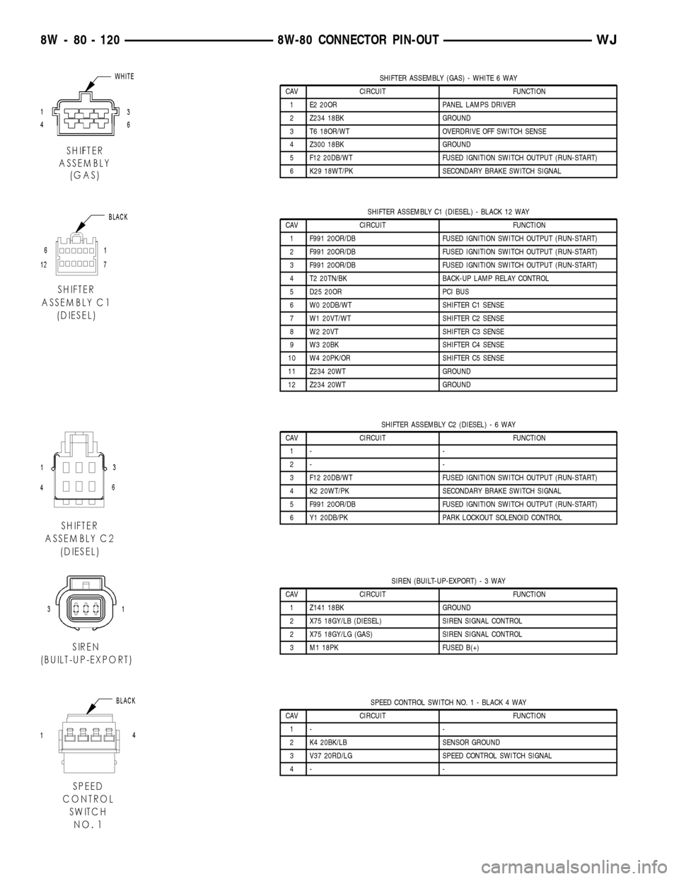
SHIFTER ASSEMBLY (GAS) - WHITE 6 WAY
CAV CIRCUIT FUNCTION
1 E2 20OR PANEL LAMPS DRIVER
2 Z234 18BK GROUND
3 T6 18OR/WT OVERDRIVE OFF SWITCH SENSE
4 Z300 18BK GROUND
5 F12 20DB/WT FUSED IGNITION SWITCH OUTPUT (RUN-START)
6 K29 18WT/PK SECONDARY BRAKE SWITCH SIGNAL
SHIFTER ASSEMBLY C1 (DIESEL) - BLACK 12 WAY
CAV CIRCUIT FUNCTION
1 F991 20OR/DB FUSED IGNITION SWITCH OUTPUT (RUN-START)
2 F991 20OR/DB FUSED IGNITION SWITCH OUTPUT (RUN-START)
3 F991 20OR/DB FUSED IGNITION SWITCH OUTPUT (RUN-START)
4 T2 20TN/BK BACK-UP LAMP RELAY CONTROL
5 D25 20OR PCI BUS
6 W0 20DB/WT SHIFTER C1 SENSE
7 W1 20VT/WT SHIFTER C2 SENSE
8 W2 20VT SHIFTER C3 SENSE
9 W3 20BK SHIFTER C4 SENSE
10 W4 20PK/OR SHIFTER C5 SENSE
11 Z234 20WT GROUND
12 Z234 20WT GROUND
SHIFTER ASSEMBLY C2 (DIESEL)-6WAY
CAV CIRCUIT FUNCTION
1- -
2- -
3 F12 20DB/WT FUSED IGNITION SWITCH OUTPUT (RUN-START)
4 K2 20WT/PK SECONDARY BRAKE SWITCH SIGNAL
5 F991 20OR/DB FUSED IGNITION SWITCH OUTPUT (RUN-START)
6 Y1 20DB/PK PARK LOCKOUT SOLENOID CONTROL
SIREN (BUILT-UP-EXPORT)-3WAY
CAV CIRCUIT FUNCTION
1 Z141 18BK GROUND
2 X75 18GY/LB (DIESEL) SIREN SIGNAL CONTROL
2 X75 18GY/LG (GAS) SIREN SIGNAL CONTROL
3 M1 18PK FUSED B(+)
SPEED CONTROL SWITCH NO. 1 - BLACK 4 WAY
CAV CIRCUIT FUNCTION
1- -
2 K4 20BK/LB SENSOR GROUND
3 V37 20RD/LG SPEED CONTROL SWITCH SIGNAL
4- -
8W - 80 - 120 8W-80 CONNECTOR PIN-OUTWJ
Page 1172 of 2199
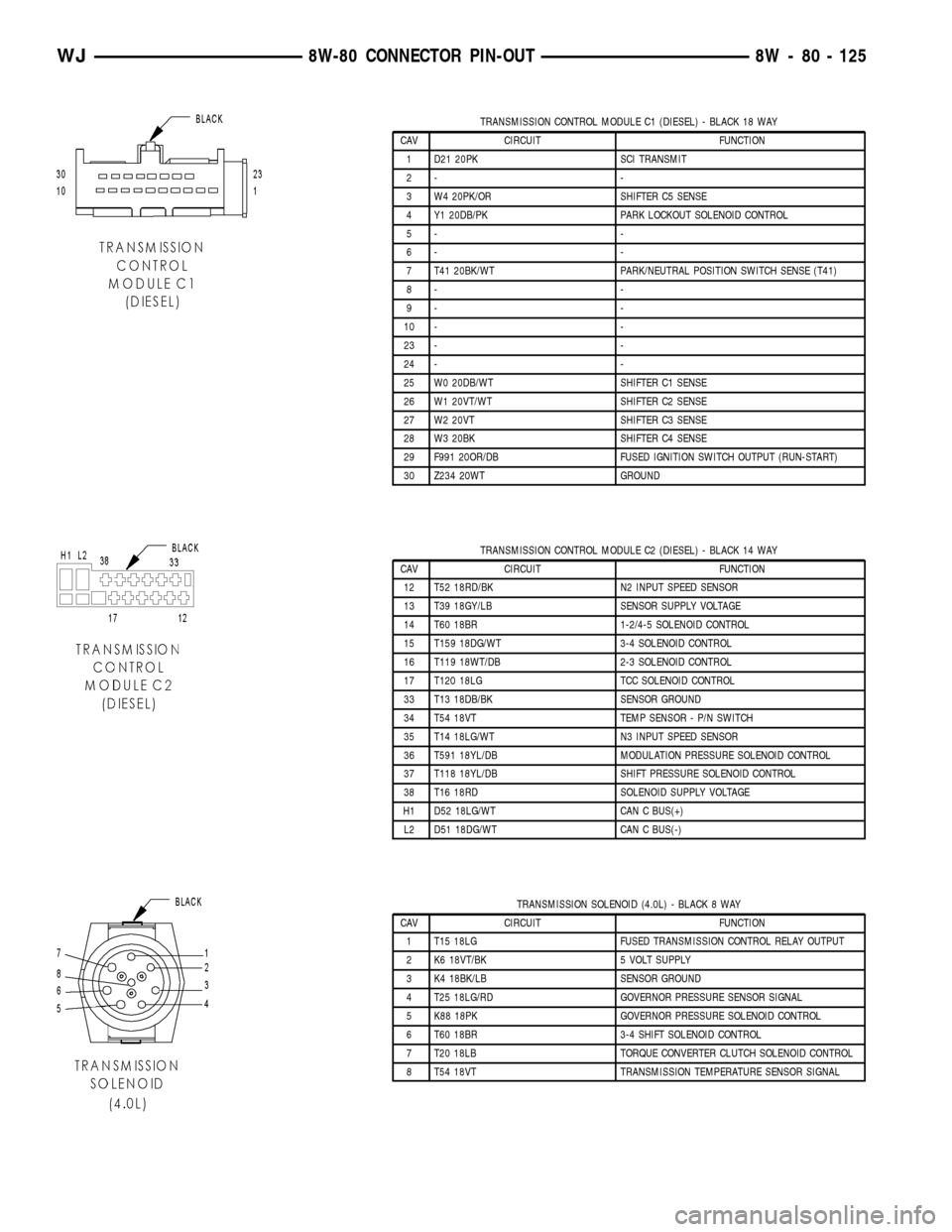
TRANSMISSION CONTROL MODULE C1 (DIESEL) - BLACK 18 WAY
CAV CIRCUIT FUNCTION
1 D21 20PK SCI TRANSMIT
2- -
3 W4 20PK/OR SHIFTER C5 SENSE
4 Y1 20DB/PK PARK LOCKOUT SOLENOID CONTROL
5- -
6- -
7 T41 20BK/WT PARK/NEUTRAL POSITION SWITCH SENSE (T41)
8- -
9- -
10 - -
23 - -
24 - -
25 W0 20DB/WT SHIFTER C1 SENSE
26 W1 20VT/WT SHIFTER C2 SENSE
27 W2 20VT SHIFTER C3 SENSE
28 W3 20BK SHIFTER C4 SENSE
29 F991 20OR/DB FUSED IGNITION SWITCH OUTPUT (RUN-START)
30 Z234 20WT GROUND
TRANSMISSION CONTROL MODULE C2 (DIESEL) - BLACK 14 WAY
CAV CIRCUIT FUNCTION
12 T52 18RD/BK N2 INPUT SPEED SENSOR
13 T39 18GY/LB SENSOR SUPPLY VOLTAGE
14 T60 18BR 1-2/4-5 SOLENOID CONTROL
15 T159 18DG/WT 3-4 SOLENOID CONTROL
16 T119 18WT/DB 2-3 SOLENOID CONTROL
17 T120 18LG TCC SOLENOID CONTROL
33 T13 18DB/BK SENSOR GROUND
34 T54 18VT TEMP SENSOR - P/N SWITCH
35 T14 18LG/WT N3 INPUT SPEED SENSOR
36 T591 18YL/DB MODULATION PRESSURE SOLENOID CONTROL
37 T118 18YL/DB SHIFT PRESSURE SOLENOID CONTROL
38 T16 18RD SOLENOID SUPPLY VOLTAGE
H1 D52 18LG/WT CAN C BUS(+)
L2 D51 18DG/WT CAN C BUS(-)
TRANSMISSION SOLENOID (4.0L) - BLACK 8 WAY
CAV CIRCUIT FUNCTION
1 T15 18LG FUSED TRANSMISSION CONTROL RELAY OUTPUT
2 K6 18VT/BK 5 VOLT SUPPLY
3 K4 18BK/LB SENSOR GROUND
4 T25 18LG/RD GOVERNOR PRESSURE SENSOR SIGNAL
5 K88 18PK GOVERNOR PRESSURE SOLENOID CONTROL
6 T60 18BR 3-4 SHIFT SOLENOID CONTROL
7 T20 18LB TORQUE CONVERTER CLUTCH SOLENOID CONTROL
8 T54 18VT TRANSMISSION TEMPERATURE SENSOR SIGNAL
WJ8W-80 CONNECTOR PIN-OUT 8W - 80 - 125
Page 1173 of 2199
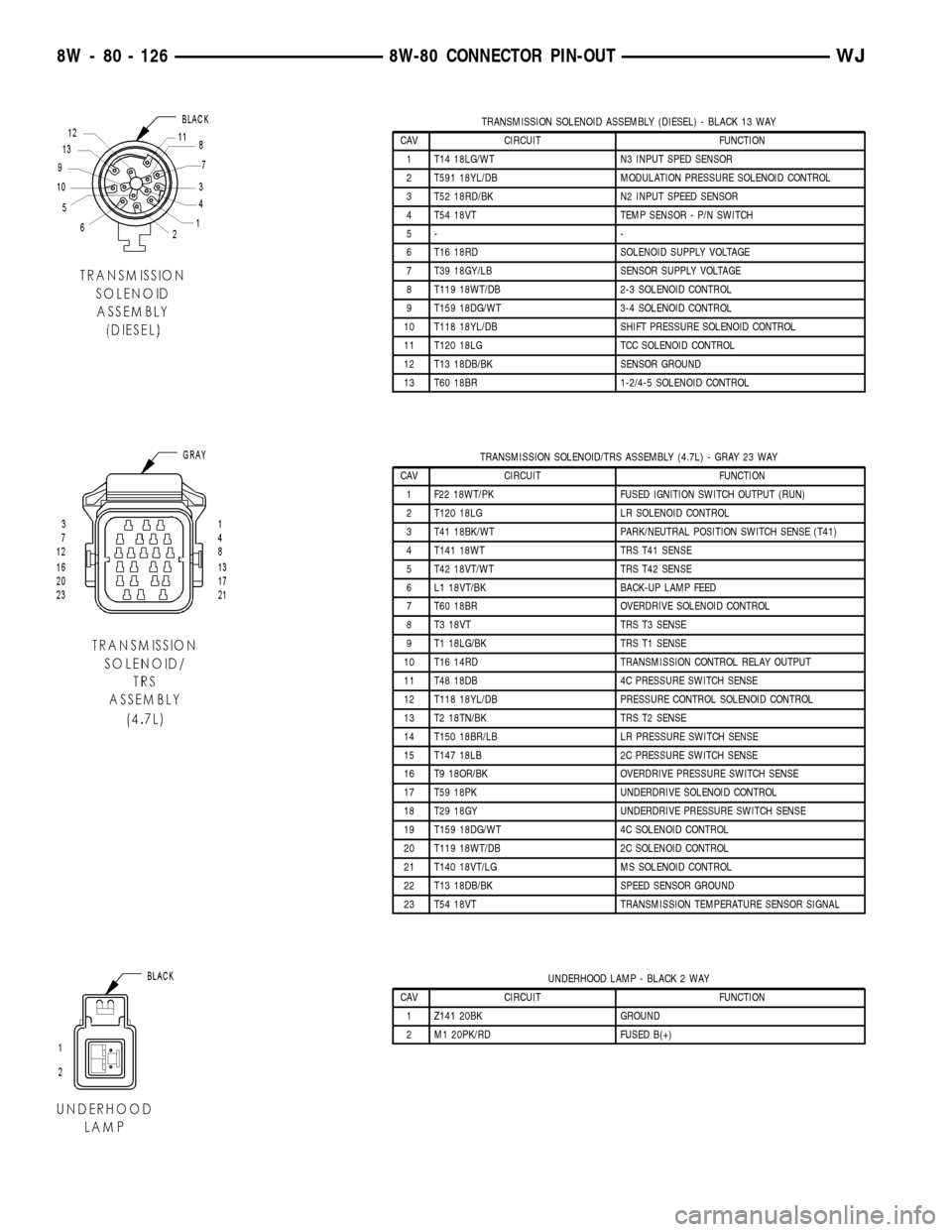
TRANSMISSION SOLENOID ASSEMBLY (DIESEL) - BLACK 13 WAY
CAV CIRCUIT FUNCTION
1 T14 18LG/WT N3 INPUT SPED SENSOR
2 T591 18YL/DB MODULATION PRESSURE SOLENOID CONTROL
3 T52 18RD/BK N2 INPUT SPEED SENSOR
4 T54 18VT TEMP SENSOR - P/N SWITCH
5- -
6 T16 18RD SOLENOID SUPPLY VOLTAGE
7 T39 18GY/LB SENSOR SUPPLY VOLTAGE
8 T119 18WT/DB 2-3 SOLENOID CONTROL
9 T159 18DG/WT 3-4 SOLENOID CONTROL
10 T118 18YL/DB SHIFT PRESSURE SOLENOID CONTROL
11 T120 18LG TCC SOLENOID CONTROL
12 T13 18DB/BK SENSOR GROUND
13 T60 18BR 1-2/4-5 SOLENOID CONTROL
TRANSMISSION SOLENOID/TRS ASSEMBLY (4.7L) - GRAY 23 WAY
CAV CIRCUIT FUNCTION
1 F22 18WT/PK FUSED IGNITION SWITCH OUTPUT (RUN)
2 T120 18LG LR SOLENOID CONTROL
3 T41 18BK/WT PARK/NEUTRAL POSITION SWITCH SENSE (T41)
4 T141 18WT TRS T41 SENSE
5 T42 18VT/WT TRS T42 SENSE
6 L1 18VT/BK BACK-UP LAMP FEED
7 T60 18BR OVERDRIVE SOLENOID CONTROL
8 T3 18VT TRS T3 SENSE
9 T1 18LG/BK TRS T1 SENSE
10 T16 14RD TRANSMISSION CONTROL RELAY OUTPUT
11 T48 18DB 4C PRESSURE SWITCH SENSE
12 T118 18YL/DB PRESSURE CONTROL SOLENOID CONTROL
13 T2 18TN/BK TRS T2 SENSE
14 T150 18BR/LB LR PRESSURE SWITCH SENSE
15 T147 18LB 2C PRESSURE SWITCH SENSE
16 T9 18OR/BK OVERDRIVE PRESSURE SWITCH SENSE
17 T59 18PK UNDERDRIVE SOLENOID CONTROL
18 T29 18GY UNDERDRIVE PRESSURE SWITCH SENSE
19 T159 18DG/WT 4C SOLENOID CONTROL
20 T119 18WT/DB 2C SOLENOID CONTROL
21 T140 18VT/LG MS SOLENOID CONTROL
22 T13 18DB/BK SPEED SENSOR GROUND
23 T54 18VT TRANSMISSION TEMPERATURE SENSOR SIGNAL
UNDERHOOD LAMP - BLACK 2 WAY
CAV CIRCUIT FUNCTION
1 Z141 20BK GROUND
2 M1 20PK/RD FUSED B(+)
8W - 80 - 126 8W-80 CONNECTOR PIN-OUTWJ
Page 1185 of 2199
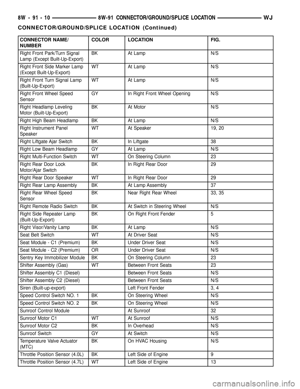
CONNECTOR NAME/
NUMBERCOLOR LOCATION FIG.
Right Front Park/Turn Signal
Lamp (Except Built-Up-Export)BK At Lamp N/S
Right Front Side Marker Lamp
(Except Built-Up-Export)WT At Lamp N/S
Right Front Turn Signal Lamp
(Built-Up-Export)WT At Lamp N/S
Right Front Wheel Speed
SensorGY In Right Front Wheel Opening N/S
Right Headlamp Leveling
Motor (Built-Up-Export)BK At Motor N/S
Right High Beam Headlamp BK At Lamp N/S
Right Instrument Panel
SpeakerWT At Speaker 19, 20
Right Liftgate Ajar Switch BK In Liftgate 38
Right Low Beam Headlamp GY At Lamp N/S
Right Multi-Function Switch WT On Steering Column 23
Right Rear Door Lock
Motor/Ajar SwitchBK In Right Rear Door 29
Right Rear Door Speaker WT In Right Rear Door 29
Right Rear Lamp Assembly BK At Lamp Assembly 37
Right Rear Wheel Speed
SensorBK Near Right Rear Wheel 33, 35
Right Remote Radio Switch BK At Switch in Steering Wheel N/S
Right Side Repeater Lamp
(Built-Up-Export)BK On Right Front Fender 5
Right Visor/Vanity Lamp BK At Lamp N/S
Seat Belt Switch WT At Driver Seat N/S
Seat Module - C1 (Premium) BK Under Driver Seat N/S
Seat Module - C2 (Premium) OR Under Driver Seat N/S
Sentry Key Immobilizer Module BK On Steering Column 23
Shifter Assembly (Gas) WT Between Front Seats 23
Shifter Assembly C1 (Diesel) Between Front Seats N/S
Shifter Assembly C2 (Diesel) Between Front Seats N/S
Siren (Built-up-export) Left Front Fender 3, 4
Speed Control Switch NO. 1 BK On Steering Wheel N/S
Speed Control Switch NO. 2 BK On Steering Wheel N/S
Sunroof Control Module At Sunroof 32
Sunroof Motor C1 WT At Sunroof N/S
Sunroof Motor C2 BK In Overhead N/S
Sunroof Switch GY At Switch N/S
Temperature Valve Actuator
(MTC)BK On HVAC Housing N/S
Throttle Position Sensor (4.0L) BK Left Side of Engine 9
Throttle Position Sensor (4.7L) WT Left Side of Engine 13
8W - 91 - 10 8W-91 CONNECTOR/GROUND/SPLICE LOCATIONWJ
CONNECTOR/GROUND/SPLICE LOCATION (Continued)
Page 1279 of 2199

CRANKSHAFT MAIN
BEARINGS
STANDARD PROCEDURE - FITTING
CRANKSHAFT MAIN BEARINGS
FITTING BEARINGS (CRANKSHAFT INSTALLED)
The main bearing caps, numbered (front to rear)
from 1 through 7 have an arrow to indicate the for-
ward position. The upper main bearing inserts are
grooved to provide oil channels while the lower
inserts are smooth.
Each bearing insert pair is selectively fitted to its
respective journal to obtain the specified operating
clearance. In production, the select fit is obtained by
using various-sized color-coded bearing insert pairs
as listed in the Main Bearing Fitting Chart. The
bearing color code appears on the edge of the insert.
The size is not stamped on bearing inserts used
for engine production.
The main bearing journal size (diameter) is identi-
fied by a color-coded paint mark (Fig. 42)on the adja-
cent cheek or counterweight towards the rear of the
crankshaft (flange end). The rear main journal, is
identified by a color-coded paint mark on the crank-
shaft rear flange.
When required, upper and lower bearing inserts of
different sizes may be used as a pair. A standard size
insert is sometimes used in combination with a 0.025
mm (0.001 inch) undersize insert to reduce the clear-
ance by 0.013 mm (0.0005 inch).Never use a pair
of bearing inserts with greater than a 0.025 mm
(0.001 inch) difference in size. Refer to the
Bearing Insert Pair Chart.NOTE: When replacing inserts, the odd size inserts
must be either all on the top (in cylinder block) or
all on the bottom (in main bearing cap).
Once the bearings have been properly fitted, (Refer
to 9 - ENGINE/ENGINE BLOCK/CRANKSHAFT
MAIN BEARINGS - INSTALLATION).
BEARING-TO-JOURNAL CLEARANCE (CRANKSHAFT
INSTALLED)
When using Plastigage, check only one bearing
clearance at a time.
Install the grooved main bearings into the cylinder
block and the non-grooved bearings into the bearing
caps.
Install the crankshaft into the upper bearings dry.
Place a strip of Plastigage across full width of the
crankshaft journal to be checked.
Install the bearing cap and tighten the bolts to 108
N´m (80 ft. lbs.) torque.
NOTE: DO NOT rotate the crankshaft. This will
cause the Plastigage to shift, resulting in an inaccu-
rate reading. Plastigage must not be permitted to
crumble. If brittle, obtain fresh stock.
Remove the bearing cap. Determine the amount of
clearance by measuring the width of the compressed
Plastigage with the scale on the Plastigage envelope
(Fig. 43). (Refer to 9 - ENGINE - SPECIFICATIONS)
for the proper clearance.
Plastigage should indicate the same clearance
across the entire width of the insert. If clearance var-
ies, it may indicate a tapered journal or foreign
material trapped behind the insert.
If the specified clearance is indicated and there are
no abnormal wear patterns, replacement of the bear-
ing inserts is not necessary. Remove the Plastigage
from the crankshaft journal and bearing insert. Pro-
ceed to (Refer to 9 - ENGINE/ENGINE BLOCK/
CRANKSHAFT MAIN BEARINGS -
INSTALLATION).
If the clearance exceeds specification, install a pair
of 0.025 mm (0.001 inch) undersize bearing inserts
and measure the clearance as described in the previ-
ous steps.
The clearance indicate with the 0.025 mm (0.001
inch) undersize insert pair installed will determine if
this insert size or some other combination will pro-
vide the specified clearance.FOR EXAMPLE:If the
clearance was 0.0762 mm (0.003 inch) originally, a
pair of 0.0254 mm (0.001 inch) undersize inserts
would reduce the clearance by 0.0254 mm (0.001
inch). The clearance would then be 0.0508 mm (0.002
inch) and within the specification. A 0.051 mm (0.002
inch) undersize bearing insert and a 0.0254 mm
(0.001 inch) undersize insert would reduce the origi-
Fig. 41 Crankshaft with Select Fit Marking Location
1 - 1/4º LETTERS
2 - (ROD)
3 - (MAIN)
9 - 36 ENGINE - 4.0LWJ
CRANKSHAFT (Continued)
Page 1467 of 2199

MAP SENSOR
DESCRIPTION
DESCRIPTION
On the 4.0L six-cylinder engine the MAP sensor is
mounted to the engine throttle body. On the 4.7L V-8
engine the MAP sensor is mounted to front of the
intake manifold.
DESCRIPTION - 4.7L
The MAP sensor is located on the front of the
intake manifold. An o-ring seals the sensor to the
intake manifold.
OPERATION
The MAP sensor is used as an input to the Power-
train Control Module (PCM). It contains a silicon
based sensing unit to provide data on the manifold
vacuum that draws the air/fuel mixture into the com-
bustion chamber. The PCM requires this information
to determine injector pulse width and spark advance.
When manifold absolute pressure (MAP) equals
Barometric pressure, the pulse width will be at max-
imum.
A 5 volt reference is supplied from the PCM and
returns a voltage signal to the PCM that reflects
manifold pressure. The zero pressure reading is 0.5V
and full scale is 4.5V. For a pressure swing of 0±15
psi, the voltage changes 4.0V. To operate the sensor,
it is supplied a regulated 4.8 to 5.1 volts. Ground is
provided through the low-noise, sensor return circuit
at the PCM.
The MAP sensor input is the number one contrib-
utor to fuel injector pulse width. The most important
function of the MAP sensor is to determine baromet-
ric pressure. The PCM needs to know if the vehicle is
at sea level or at a higher altitude, because the air
density changes with altitude. It will also help to cor-
rect for varying barometric pressure. Barometric
pressure and altitude have a direct inverse correla-
tion; as altitude goes up, barometric goes down. At
key-on, the PCM powers up and looks at MAP volt-
age, and based upon the voltage it sees, it knows the
current barometric pressure (relative to altitude).
Once the engine starts, the PCM looks at the voltage
again, continuously every 12 milliseconds, and com-
pares the current voltage to what it was at key-on.
The difference between current voltage and what it
was at key-on, is manifold vacuum.
During key-on (engine not running) the sensor
reads (updates) barometric pressure. A normal range
can be obtained by monitoring a known good sensor.
As the altitude increases, the air becomes thinner
(less oxygen). If a vehicle is started and driven to avery different altitude than where it was at key-on,
the barometric pressure needs to be updated. Any
time the PCM sees Wide Open Throttle (WOT), based
upon Throttle Position Sensor (TPS) angle and RPM,
it will update barometric pressure in the MAP mem-
ory cell. With periodic updates, the PCM can make
its calculations more effectively.
The PCM uses the MAP sensor input to aid in cal-
culating the following:
²Manifold pressure
²Barometric pressure
²Engine load
²Injector pulse-width
²Spark-advance programs
²Shift-point strategies (certain automatic trans-
missions only)
²Idle speed
²Decel fuel shutoff
The MAP sensor signal is provided from a single
piezoresistive element located in the center of a dia-
phragm. The element and diaphragm are both made
of silicone. As manifold pressure changes, the dia-
phragm moves causing the element to deflect, which
stresses the silicone. When silicone is exposed to
stress, its resistance changes. As manifold vacuum
increases, the MAP sensor input voltage decreases
proportionally. The sensor also contains electronics
that condition the signal and provide temperature
compensation.
The PCM recognizes a decrease in manifold pres-
sure by monitoring a decrease in voltage from the
reading stored in the barometric pressure memory
cell. The MAP sensor is a linear sensor; meaning as
pressure changes, voltage changes proportionately.
The range of voltage output from the sensor is usu-
ally between 4.6 volts at sea level to as low as 0.3
volts at 26 in. of Hg. Barometric pressure is the pres-
sure exerted by the atmosphere upon an object. At
sea level on a standard day, no storm, barometric
pressure is approximately 29.92 in Hg. For every 100
feet of altitude, barometric pressure drops .10 in. Hg.
If a storm goes through it can change barometric
pressure from what should be present for that alti-
tude. You should know what the average pressure
and corresponding barometric pressure is for your
area.
REMOVAL
REMOVAL - 4.0L
The MAP sensor is mounted to the side of the
throttle body (Fig. 40). An L-shaped rubber fitting is
used to connect the MAP sensor to throttle body (Fig.
31).
(1) Remove air cleaner duct and air resonator box
at throttle body.
14 - 48 FUEL INJECTIONWJ
Page 1487 of 2199

(10) Disconnect the multifuction switch (Fig. 9)
and ignition switch harness.
(11) Remove the multifuction switch screw from
underneath the switch (Fig. 10). Slide the multifuc-
tion switch and clock spring off the column as an
assembly (Fig. 11).(12) Turn the ignition key to the on position then
release and remove the shifter interlock cable (Fig.
12) from the ignition lock cylinder housing.
Fig. 9 Multifuction Switch Harness
1 - MULTIFUNCTION SWITCH
2 - MULTIFUNCTION SWITCH HARNESS
Fig. 10 Multifuction
1 - CLOCK SPRING
2 - SCREW
3 - MULTI-FUNCTION SWITCH MOUNTING HOUSING
Fig. 11 Multifuction Switch And Clock Spring
1 - MULTI-FUNCTION SWITCH ASSEMBLY
2 - CLOCKSPRING
Fig. 12 Shifter Interlock Cable
1 - LOCK CYLINDER HOUSING
2 - INTERLOCK CABLE
19 - 10 COLUMNWJ
COLUMN (Continued)
Page 1488 of 2199

(13) Remove the column coupler bolt (Fig. 13) and
slide the coupler off the column shaft.
(14) Remove the column mounting nuts (Fig. 13)
and lower column off mounting studs. Remove the
column from the vehicle.
(15) Remove the ignition switch, cylinder and
SKIM, (Refer to 19 - STEERING/COLUMN/LOCK
CYLINDER HOUSING - REMOVAL). (Fig. 14).INSTALLATION
WARNING: BEFORE SERVICING THE STEERING COL-
UMN THE AIRBAG SYSTEM MUST BE DISARMED.
FAILURE TO DO SO MAY RESULT IN ACCIDENTAL
DEPLOYMENT OF THE AIRBAG AND POSSIBLE PER-
SONAL INJURY. (Refer to 8 - ELECTRICAL/RE-
STRAINTS/DRIVER AIRBAG - INSTALLATION).
(1) Install the ignition switch, cylinder and SKIM-
,(Refer to 19 - STEERING/COLUMN/IGNITION
SWITCH - INSTALLATION).
(2) Install the column into the vehicle and lift the
column up onto the mounting studs. Install the
mounting nuts and tighten to 12 N´m (105 in. lbs.).
(3) Slid the coupler onto the column shaft and
install the coupler bolt. Tighten the coupler bolt to 49
N´m (36 ft. lbs.).
(4) Turn the ignition key to the on position then
release and install the shifter interlock cable (Fig.
12) into ignition lock cylinder housing.
(5) Verify ignition switch and shifter interlock
operation.,(Refer to 21 - TRANSMISSION/TRANS-
AXLE/AUTOMATIC - 42RE/GEAR SHIFT CABLE -
ADJUSTMENTS).
(6) Slide the multifuction switch and clock spring
onto the column as an assembly (Fig. 11).
(7) Install the multifuction switch mounting screw
(Fig. 10).
(8) Connect the multifuction switch (Fig. 9) and
ignition switch harness.
(9) Install the upper fixed shroud and mounting
screws (Fig. 8).
(10) Install the lower steering column shroud to
the steering column. Install and tighten the mount-
ing screw.
(11) Install the upper column shroud. Align the
upper shroud to the lower shroud and snap the two
shroud halves together.
(12) Install the knee blocker cover (Fig. 5),(Refer
to 23 - BODY/INSTRUMENT PANEL - INSTALLA-
TION).
(13) Install the cluster bezel by inserting it into
the instrument panel (Fig. 4).
(14) Align the steering wheel with the column
index spline and install the wheel on the column
shaft. Pull the clockspring wire harness through the
steering wheel armature spokes.
(15) Install and tighten the steering wheel mount-
ing nut to 61 N´m (45 ft. lbs.).
(16) Connect the steering wheel wire harness con-
nector to the clock spring connector.
(17) Install the airbag,(Refer to 8 - ELECTRICAL/
RESTRAINTS/DRIVER AIRBAG - INSTALLATION).
(18) Connect the negative (ground) cable to the
battery.
Fig. 13 Column Coupler Bolt And Mounting Nuts
1 - COLUMN MOUNTING NUTS
2 - COUPLER BOLT
Fig. 14 Ignition Switch And SKIM
1 - SKIM
2 - IGNITION SWITCH
WJCOLUMN 19 - 11
COLUMN (Continued)