air JEEP GRAND CHEROKEE 2002 WJ / 2.G Workshop Manual
[x] Cancel search | Manufacturer: JEEP, Model Year: 2002, Model line: GRAND CHEROKEE, Model: JEEP GRAND CHEROKEE 2002 WJ / 2.GPages: 2199, PDF Size: 76.01 MB
Page 1783 of 2199

A solenoid can also be described by the method by
which it is controlled. Some of the possibilities
include variable force, pulse-width modulated, con-
stant ON, or duty cycle. The variable force and pulse-
width modulated versions utilize similar methods to
control the current flow through the solenoid to posi-
tion the solenoid plunger at a desired position some-
where between full ON and full OFF. The constant
ON and duty cycled versions control the voltage
across the solenoid to allow either full flow or no flow
through the solenoid's valve.
OPERATION
When an electrical current is applied to the sole-
noid coil, a magnetic field is created which produces
an attraction to the plunger, causing the plunger to
move and work against the spring pressure and the
load applied by the fluid the valve is controlling. The
plunger is normally directly attached to the valve
which it is to operate. When the current is removed
from the coil, the attraction is removed and the
plunger will return to its original position due to
spring pressure.
The plunger is made of a conductive material and
accomplishes this movement by providing a path for
the magnetic field to flow. By keeping the air gap
between the plunger and the coil to the minimum
necessary to allow free movement of the plunger, the
magnetic field is maximized.
TORQUE CONVERTER
DESCRIPTION
The torque converter (Fig. 109) is a hydraulic
device that couples the engine crankshaft to the
transmission. The torque converter consists of an
outer shell with an internal turbine, a stator, an
overrunning clutch, an impeller and an electronically
applied converter clutch. The converter clutch pro-vides reduced engine speed and greater fuel economy
when engaged. Clutch engagement also provides
reduced transmission fluid temperatures. The con-
verter clutch engages in third gear. The torque con-
verter hub drives the transmission oil (fluid) pump
and contains an o-ring seal to better control oil flow.
The torque converter is a sealed, welded unit that
is not repairable and is serviced as an assembly.
CAUTION: The torque converter must be replaced if
a transmission failure resulted in large amounts of
metal or fiber contamination in the fluid. If the fluid
is contaminated, flush the fluid cooler and lines.
Fig. 109 Torque Converter Assembly
1 - TURBINE ASSEMBLY
2-STATOR
3 - CONVERTER HUB
4 - O-RING
5 - IMPELLER ASSEMBLY
6 - CONVERTER CLUTCH PISTON
7 - TURBINE HUB
21 - 264 AUTOMATIC TRANSMISSION - 545RFEWJ
SOLENOIDS (Continued)
Page 1796 of 2199

CLEANING
Clean the valve housings, valves, plugs, springs,
and separator plates with a standard parts cleaning
solution only. Do not use gasoline, kerosene, or any
type of caustic solution. (Fig. 131)
Do not immerse any of the electrical components in
cleaning solution. Clean the electrical components by
wiping them off with dry shop towels only.
Dry all except the electrical parts with compressed
air. Make sure all passages are clean and free from
obstructions.Do not use rags or shop towels to
dry or wipe off valve body components. Lint
from these materials can stick to valve body
parts, interfere with valve operation, and clog
filters and fluid passages.
INSPECTION
Inspect all of the valve body mating surfaces for
scratches, nicks, burrs, or distortion. Use a straight-edge to check surface flatness. Minor scratches may
be removed with crocus cloth using only very light
pressure.
Minor distortion of a valve body mating surface
may be corrected by smoothing the surface with a
sheet of crocus cloth. Position the crocus cloth on a
surface plate, sheet of plate glass or equally flat sur-
face. If distortion is severe or any surfaces are
heavily scored, the valve body will have to be
replaced.
Inspect the valves and plugs (Fig. 132) for
scratches, burrs, nicks, or scores. Minor surface
scratches on steel valves and plugs can be removed
with crocus cloth butdo not round off the edges
of the valve or plug lands.Maintaining sharpness
of these edges is vitally important. The edges prevent
foreign matter from lodging between the valves and
plugs and the bore.
Fig. 130 Valve Body Components
1 - SOLENOID SWITCH VALVE
2 - MANUAL VALVE
3 - LOW REVERSE SWITCH VALVE
4 - LOW REVERSE ACCUMULATOR
5 - 2ND CLUTCH ACCUMULATOR
6 - UNDERDRIVE ACCUMULATOR
7 - OVERDRIVE ACCUMULATOR
8 - 4TH CLUTCH ACCUMULATOR
9 - CHECK BALLS (7)
Fig. 131 Valve Body Components
1 - SOLENOID SWITCH VALVE
2 - MANUAL VALVE
3 - LOW REVERSE SWITCH VALVE
4 - LOW REVERSE ACCUMULATOR
5 - 2ND CLUTCH ACCUMULATOR
6 - UNDERDRIVE ACCUMULATOR
7 - OVERDRIVE ACCUMULATOR
8 - 4TH CLUTCH ACCUMULATOR
9 - CHECK BALLS (7)
WJAUTOMATIC TRANSMISSION - 545RFE 21 - 277
VALVE BODY (Continued)
Page 1800 of 2199

OPERATION
The input gear is splined to the transmission out-
put shaft. It drives the mainshaft through the plan-
etary gear and range hub. The front output shaft is
operated by a drive chain that connects the shaft to a
drive sprocket on the mainshaft. The drive sprocket
is engaged/disengaged by the mode fork, which oper-
ates the mode sleeve and hub. The sleeve and hub
are not equipped with a synchro mechanism for shift-
ing.
OPERATING RANGES
NV242 operating ranges are 2WD (2-wheel drive),
4x4 part-time, 4x4 full time, and 4 Lo.
The 2WD and 4x4 full time ranges can be used at
any time and on any road surface.
The 4x4 part-time and 4 Lo ranges are for off road
use only. The only time these ranges can be used on
hard surface roads, is when the surface is covered
with snow and ice.
DIAGNOSIS AND TESTING - TRANSFER CASE - NV242
DIAGNOSIS CHART
CONDITION POSSIBLE CAUSE CORRECTION
Transfer case difficult to shift or will
not shift into desired range.1) Transfer case shift linkage
binding.1) Repair or replace linkage as
necessary.
2) Insufficient or incorrect lubricant. 2) Drain and refill transfer case with
the correct type and quantity of
lubricant.
3) Internal transfer case
components binding, worn, or
damaged.3) Repair or replace components as
necessary.
Transfer case noisy in all drive
modes.1) Insufficient or incorrect lubricant. 1) Drain and refill transfer case with
the correct type and quantity of
lubricant.
Lubricant leaking from transfer case
seals or vent.1) Transfer case overfilled. 1) Drain lubricant to the correct
level.
2) Transfer case vent closed or
restricted.2) Clean or replace vent as
necessary.
3) Transfer case seals damaged or
installed incorrectly.3) Replace suspect seal.
Transfer case will not shift through
4X4 part time range (light remains
on)1) Incomplete shift due to drivetrain
torque load.1) Momentarily release the
accelerator pedal to complete the
shift.
2) Incorrect tire pressure. 2) Correct tire pressure as
necessary.
3) Excessive Tire wear. 3) Correct tire condition as
necessary.
4) Excessive vehicle loading. 4) Correct as necessary.
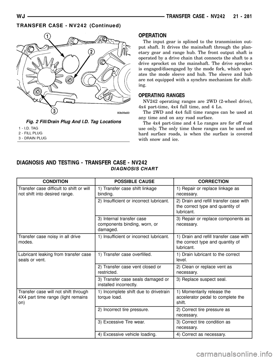
Fig. 2 Fill/Drain Plug And I.D. Tag Locations
1 - I.D. TAG
2 - FILL PLUG
3 - DRAIN PLUG
WJTRANSFER CASE - NV242 21 - 281
TRANSFER CASE - NV242 (Continued)
Page 1803 of 2199

REAR RETAINER - NV242HD
(1) Remove extension housing bolts.
(2) Tap extension housing with plastic or rawhide
mallet to loosen sealer (Fig. 10).
(3) Separate extension housing from rear retainer.
(4) Remove rear bearing snap-ring (Fig. 11).
(5) Remove bolts holding rear retainer to rear case
half.
(6) Loosen rear retainer with pry tool to break
sealer bead. Pry only against retainer boss as shown
(Fig. 12).
(7) Slide retainer off case and output shaft (Fig.
13).
OIL PUMP AND REAR CASE HALF
(1) Remove rear bearing O.D. retaining ring with
snap ring pliers. Then tilt pump and slide it off out-
put shaft (Fig. 14)
(2) Remove pickup tube O-ring from pump (Fig.
15) but do not disassemble pump; it is not a repair-
able part.
(3) Remove seal from oil pump with pry tool.
(4) Remove bolts attaching rear case to front case
(Fig. 16). Note position of the two black finish bolts
at each end of the case. These bolts go through the
case dowels and require a washer under the bolt
head.
Fig. 10 Remove Extension Housing
1 - EXTENSION HOUSING
2 - PLASTIC HAMMER
3 - REAR RETAINER
Fig. 11 Remove the Output Bearing Snap-ring
1 - REAR RETAINER
2 - SNAP-RING
3 - REAR BEARING
Fig. 12 Loosening Rear Retainer
1 - REAR RETAINER
2-TAB(2)
3 - SCREWDRIVER
4-TAB
Fig. 13 Rear Retainer Removal
1 - MAINSHAFT
2 - REAR RETAINER
21 - 284 TRANSFER CASE - NV242WJ
TRANSFER CASE - NV242 (Continued)
Page 1811 of 2199

(7) Inspect low range annulus gear (Fig. 42).Gear
is not a serviceable component. If damaged,
replace gear and front case as assembly.
(8) Remove oil seals from following components:
²front bearing retainer.
²rear retainer.
²oil pump.
²case halves.
DIFFERENTIAL
(1) Mark differential case halves for reference.
(2) Remove differential case bolts.
(3) Invert differential on workbench.
(4) Separate top case from bottom case. Use slots
in case halves to pry them apart (Fig. 43).
(5) Remove thrust washers and planet gears from
case pins (Fig. 44).
(6) Remove mainshaft and sprocket gears from
bottom case (Fig. 45). Note gear position for reference
before separating them.
CLEANING
Clean the transfer case parts with a standard
parts cleaning solvent. Remove all traces of sealer
from the cases and retainers with a scraper and all
purpose cleaner. Use compressed air to remove sol-
vent residue from oil feed passages in the case
halves, retainers, gears, and shafts.
The oil pickup screen can be cleaned with solvent.
Shake excess solvent from the screen after cleaning
and allow it to air dry. Do not use compressed air.
Fig. 42 Inspecting Low Range Annulus Gear
1 - LOW RANGE ANNULUS GEAR
Fig. 43 Separating Differential Case Halves
1 - TOP CASE
2 - CASE BOLTS
3 - CASE BOLTS
4 - CASE SLOTS
5 - CASE BOLTS
Fig. 44 Planet Gears And Thrust Washer Removal
1 - MAINSHAFT GEAR
2 - THRUST WASHERS (12)
3 - PLANET GEARS (6)
21 - 292 TRANSFER CASE - NV242WJ
TRANSFER CASE - NV242 (Continued)
Page 1814 of 2199

REAR OUTPUT SHAFT/YOKE/DRIVE CHAIN
Check condition of the seal contact surfaces of the
yoke slinger (Fig. 49). This surface must be clean and
smooth to ensure proper seal life. Replace the yoke
nut and seal washer as neither part should be
reused.
Inspect the shaft threads, sprocket teeth, and bear-
ing surfaces. Minor nicks on the teeth can be
smoothed with an oilstone. Use 320-400 grit emery to
smooth minor scratches on the shaft bearing sur-
faces. Rough threads on the shaft can be chased if
necessary. Replace the shaft if the threads are dam-
aged, bearing surfaces are scored, or if any sprocket
teeth are cracked or broken.
Examine the drive chain and shaft bearings.
Replace the chain and both sprockets if the chain is
stretched, distorted, or if any of the links bind.
Replace the bearings if rough, or noisy.
LOW RANGE ANNULUS GEAR
Inspect annulus gear condition carefully. The gear
is only serviced as part of the front case. If the gear
is damaged, it will be necessary to replace the gear
and front case as an assembly. Do not attempt to
remove the gear (Fig. 50)
FRONT-REAR CASES AND FRONT RETAINER
Inspect the cases and retainer for wear and dam-
age. Clean the sealing surfaces with a scraper and
3M all purpose cleaner. This will ensure proper
sealer adhesion at assembly. Replace the input
retainer seal; do not reuse it.Check case condition. If leaks were a problem, look
for gouges and severe scoring of case sealing sur-
faces. Also make sure the front case mounting studs
are in good condition.
Check the front case mounting studs and vent
tube. The tube can be secured with LoctiteŸ 271 or
680 if loose. The stud threads can be cleaned up with
a die if necessary. Also check condition of the fill/
drain plug threads in the rear case. The threads can
be repaired with a thread chaser or tap if necessary.
Or the threads can be repaired with HelicoilŸ stain-
less steel inserts if required.
OIL PUMP/OIL PICKUP
Examine the oil pump pickup parts. Replace the
pump if any part appears to be worn or damaged. Do
not disassemble the pump as individual parts are not
available. The pump is only available as a complete
assembly. The pickup screen, hose, and tube are the
only serviceable parts and are available separately.
ASSEMBLY
Lubricate transfer case components with automatic
transmission fluid or petroleum jelly (where indi-
cated) during assembly.
CAUTION: The bearing bores in various transfer
case components contain oil feed holes. Make sure
replacement bearings do not block the holes.
Fig. 49 Seal Contact Surface Of Yoke Slinger
1 - FRONT SLINGER (PART OF YOKE)
2 - SEAL CONTACT SURFACE MUST BE CLEAN AND SMOOTH
Fig. 50 Low Range Annulus Gear
1 - FRONT CASE
2 - LOW RANGE ANNULUS GEAR
WJTRANSFER CASE - NV242 21 - 295
TRANSFER CASE - NV242 (Continued)
Page 1835 of 2199

OPERATION
Under normal driving conditions, the system oper-
ates conventionally, and the majority of available
torque is applied to the rear wheels. However, when
front-to-rear wheel speed variations exist, the pro-
gressive differential transfers torque to the axle with
the better traction, thus minimizing wheel spin and
maximizing control.
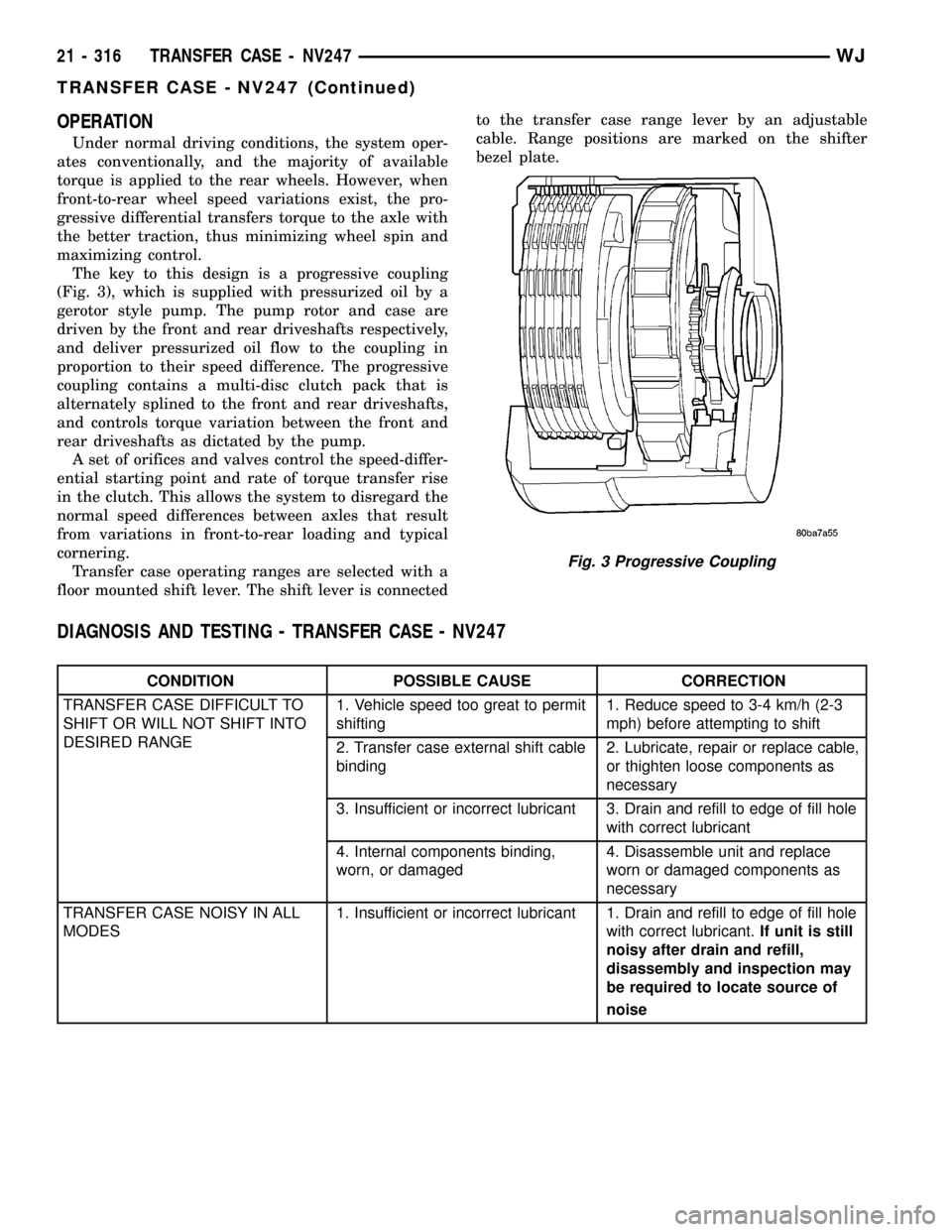
The key to this design is a progressive coupling
(Fig. 3), which is supplied with pressurized oil by a
gerotor style pump. The pump rotor and case are
driven by the front and rear driveshafts respectively,
and deliver pressurized oil flow to the coupling in
proportion to their speed difference. The progressive
coupling contains a multi-disc clutch pack that is
alternately splined to the front and rear driveshafts,
and controls torque variation between the front and
rear driveshafts as dictated by the pump.
A set of orifices and valves control the speed-differ-
ential starting point and rate of torque transfer rise
in the clutch. This allows the system to disregard the
normal speed differences between axles that result
from variations in front-to-rear loading and typical
cornering.
Transfer case operating ranges are selected with a
floor mounted shift lever. The shift lever is connectedto the transfer case range lever by an adjustable
cable. Range positions are marked on the shifter
bezel plate.
DIAGNOSIS AND TESTING - TRANSFER CASE - NV247
CONDITION POSSIBLE CAUSE CORRECTION
TRANSFER CASE DIFFICULT TO
SHIFT OR WILL NOT SHIFT INTO
DESIRED RANGE1. Vehicle speed too great to permit
shifting1. Reduce speed to 3-4 km/h (2-3
mph) before attempting to shift
2. Transfer case external shift cable
binding2. Lubricate, repair or replace cable,
or thighten loose components as
necessary
3. Insufficient or incorrect lubricant 3. Drain and refill to edge of fill hole
with correct lubricant
4. Internal components binding,
worn, or damaged4. Disassemble unit and replace
worn or damaged components as
necessary
TRANSFER CASE NOISY IN ALL
MODES1. Insufficient or incorrect lubricant 1. Drain and refill to edge of fill hole
with correct lubricant.If unit is still
noisy after drain and refill,
disassembly and inspection may
be required to locate source of
noise
Fig. 3 Progressive Coupling
21 - 316 TRANSFER CASE - NV247WJ
TRANSFER CASE - NV247 (Continued)
Page 1836 of 2199

CONDITION POSSIBLE CAUSE CORRECTION
NOISY INÐOR JUMPS OUT OF
4WD LOW RANGE1. Transfer case not completely
engaged in 4WD LOW (possibly
from shift to 4L while rolling)1. Stop vehicle, shift transfer case
to neutral, then shift back to 4WD
LOW
2. Shift linkage loose, binding, or is
misadjusted2. Tighten, lubricate, or repair
linkage as necessary. Adjust linkage
if necessary
3. Range fork cracked, inserts
worn, or fork is binding on shift rail3. Disassemble unit and repair as
necessary
4. Annulus gear or lockplate worn
or damaged4. Disassemble unit and repair as
necessary
LUBRICANT LEAKING FROM
OUTPUT SHAFT SEALS OR FROM
VENT1. Transfer case over filled 1. Drain to correct level
2. Vent closed or restricted 2. Clear or replace vent if necessary
3. Output shaft seals damaged or
installed correctly3. Replace seals. Be sure seal lip
faces interior of case when installed.
Also be sure yoke seal surfaces are
not scored or nicked. Remove
scores and nicks with fine
sandpaper or replace yoke(s) if
necessary.
REMOVAL
(1) Shift transfer case into NEUTRAL.
(2) Raise vehicle.
(3) Remove transfer case drain plug and drain
transfer case lubricant.
(4) Mark front and rear propeller shaft yokes for
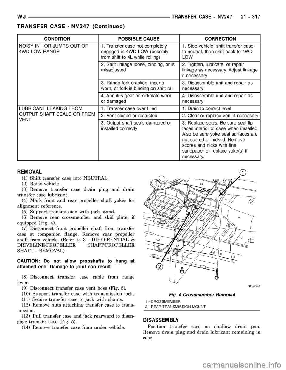
alignment reference.
(5) Support transmission with jack stand.
(6) Remove rear crossmember and skid plate, if
equipped (Fig. 4).
(7) Disconnect front propeller shaft from transfer
case at companion flange. Remove rear propeller
shaft from vehicle. (Refer to 3 - DIFFERENTIAL &
DRIVELINE/PROPELLER SHAFT/PROPELLER
SHAFT - REMOVAL)
CAUTION: Do not allow propshafts to hang at
attached end. Damage to joint can result.
(8) Disconnect transfer case cable from range
lever.
(9) Disconnect transfer case vent hose (Fig. 5).
(10) Support transfer case with transmission jack.
(11) Secure transfer case to jack with chains.
(12) Remove nuts attaching transfer case to trans-
mission.
(13) Pull transfer case and jack rearward to disen-
gage transfer case (Fig. 5).
(14) Remove transfer case from under vehicle.
DISASSEMBLY
Position transfer case on shallow drain pan.
Remove drain plug and drain lubricant remaining in
case.
Fig. 4 Crossmember Removal
1 - CROSSMEMBER
2 - REAR TRANSMISSION MOUNT
WJTRANSFER CASE - NV247 21 - 317
TRANSFER CASE - NV247 (Continued)
Page 1843 of 2199

(2) Remove retainer (Fig. 28).
(3) Remove front tabbed thrust washer (Fig. 29).
(4) Remove input gear (Fig. 30).
(5) Remove rear tabbed thrust washer from low
range gear (Fig. 31).
CLEANING
Clean the transfer case components with parts
cleaning solvent. Flush the oil passages in the cases
and drivetrain components with solvent. This will
help remove dirt and particles from these passages.
Dry the transfer case components with compressed
air or allow them to air dry on clean shop towels.
Apply compressed air through all oil passages in
the cases and gear components to clear them of any
residue.
INSPECTION
MAINSHAFT
Examine the mainshaft components carefully for
evidence of wear or damage.
Replace the thrust washers if worn or damaged.
Replace the mainshaft and sprocket gears if the
teeth or gear bores are worn or damaged.
Replace the mainshaft bearings if worn, flat spot-
ted, brinelled, or damaged in any way.
Replace the mainshaft if it is bent, exhibits wear or
damage to the bearing surfaces, splines or gear teeth.
Fig. 28 Input Gear Retainer
1 - INPUT GEAR
2 - LOW RANGE GEAR
3 - RETAINER
Fig. 29 Front Tabbed Thrust Washer
1 - FRONT TABBED THRUST WASHER
Fig. 30 Input Gear Removal
1 - INPUT GEAR
2 - LOW RANGE GEAR
Fig. 31 Rear Tabbed Thrust Washer Removal
1 - LOW RANGE GEAR
2 - REAR TABBED THRUST WASHER
21 - 324 TRANSFER CASE - NV247WJ
TRANSFER CASE - NV247 (Continued)
Page 1860 of 2199

TIRES/WHEELS
TABLE OF CONTENTS
page page
TIRES/WHEELS
DIAGNOSIS AND TESTING - TIRE AND
WHEEL RUNOUT......................1
STANDARD PROCEDURE
STANDARD PROCEDURE - TIRE AND
WHEEL BALANCE......................2
STANDARD PROCEDURE - MATCH
MOUNTING...........................4
STANDARD PROCEDURE - TIRE ROTATION . 5
STANDARD PROCEDURE - WHEEL
INSTALLATION........................5
TIRES
DESCRIPTION
DESCRIPTION - TIRES..................6
DESCRIPTION - RADIAL±PLY TIRES.......6
DESCRIPTION - TIRE INFLATION
PRESSURES..........................6
DESCRIPTION - TIRE PRESSURE FOR
HIGH SPEED..........................7
DESCRIPTION - REPLACEMENT TIRES.....7
DIAGNOSIS AND TESTING
DIAGNOSIS AND TESTING - PRESSURE
GAUGES.............................8
DIAGNOSIS AND TESTING - TREAD WEAR
INDICATORS..........................8
DIAGNOSIS AND TESTING - TIRE WEAR
PATTERNS...........................8
DIAGNOSIS AND TESTING - TIRE NOISE
OR VIBRATION........................8STANDARD PROCEDURE - REPAIRING
LEAKS...............................8
CLEANING.............................9
SPECIFICATIONS
TIRES...............................9
SPECIFICATIONS -.....................9
SPARE TIRE
DESCRIPTION - SPARE / TEMPORARY TIRE . . 10
WHEELS
DESCRIPTION.........................10
DIAGNOSIS AND TESTING - WHEEL
INSPECTION.........................10
STANDARD PROCEDURE - WHEEL
REPLACEMENT.......................10
SPECIFICATIONS
TORQUE CHART......................11
STUDS
REMOVAL.............................11
INSTALLATION.........................11
TIRE PRESSURE MONITORING
DESCRIPTION.........................12
OPERATION...........................12
DIAGNOSIS AND TESTING - TIRE PRESSURE
MONITORING SYSTEM.................12
SENSOR
REMOVAL - TIRE PRESSURE SENSOR/
TRANSMITTER.......................12
INSTALLATION - TIRE PRESSURE SENSOR/
TRANSMITTER.......................13
TIRES/WHEELS
DIAGNOSIS AND TESTING - TIRE AND WHEEL
RUNOUT
Radial runout is the difference between the high
and low points on the tire or wheel (Fig. 1).
Lateral runout is thewobbleof the tire or wheel.
Radial runout of more than 1.5 mm (.060 inch)
measured at the center line of the tread may cause
the vehicle to shake.
Lateral runout of more than 2.0 mm (.080 inch)
measured near the shoulder of the tire may cause the
vehicle to shake.
Sometimes radial runout can be reduced. Relocate
the wheel and tire assembly on the mounting studs
(See Method 1). If this does not reduce runout to an
acceptable level, the tire can be rotated on the wheel.
(See Method 2).
METHOD 1 (RELOCATE WHEEL ON HUB)
(1) Drive vehicle a short distance to eliminate tire
flat spotting from a parked position.
(2) Check wheel bearings and adjust if adjustable
or replace if necessary.
(3) Check the wheel mounting surface.
(4) Relocate wheel on the mounting, two studs
over from the original position.
(5) Tighten wheel nuts until all are properly
torqued, to eliminate brake distortion.
(6) Check radial runout. If still excessive, mark
tire sidewall, wheel, and stud at point of maximum
runout and proceed to Method 2.
METHOD 2 (RELOCATE TIRE ON WHEEL)
NOTE: Rotating the tire on wheel is particularly
effective when there is runout in both tire and
wheel.
WJTIRES/WHEELS 22 - 1