23 body JEEP GRAND CHEROKEE 2002 WJ / 2.G Workshop Manual
[x] Cancel search | Manufacturer: JEEP, Model Year: 2002, Model line: GRAND CHEROKEE, Model: JEEP GRAND CHEROKEE 2002 WJ / 2.GPages: 2199, PDF Size: 76.01 MB
Page 1943 of 2199
ASSIST HANDLE
REMOVAL
(1) Remove the screws holding the assist handle to
the roof panel.
(2) Remove the assist handle from the roof panel.
INSTALLATION
(1) Align the assist handle with the screw holes in
the roof panel.
(2) Install the screws holding the assist handle to
the roof panel.
B-PILLAR LOWER TRIM
REMOVAL
(1) Remove front door sill trim (Refer to 23 -
BODY/INTERIOR/DOOR SILL TRIM - REMOVAL).
(2) Remove front seat shoulder belt anchor bolt.(3) Remove front seat shoulder belt height adjust-
ment knob and turning loop.
(4) Remove screw attaching front of quarter panel
trim to floor.
(5) Remove screws attaching front and rear of
B-pillar lower trim to floor.
(6) Remove screw attaching B-pillar lower trim to
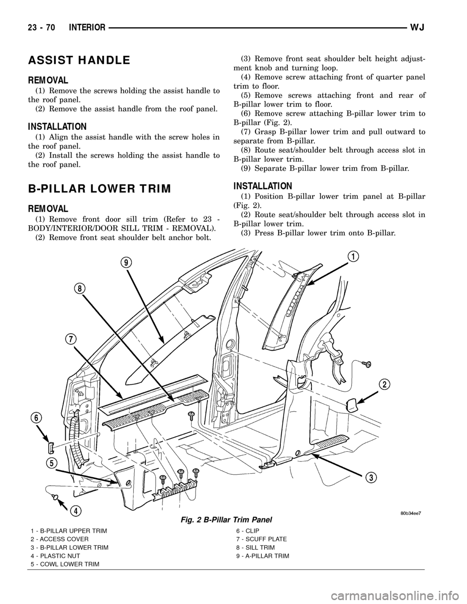
B-pillar (Fig. 2).
(7) Grasp B-pillar lower trim and pull outward to
separate from B-pillar.
(8) Route seat/shoulder belt through access slot in
B-pillar lower trim.
(9) Separate B-pillar lower trim from B-pillar.
INSTALLATION
(1) Position B-pillar lower trim panel at B-pillar
(Fig. 2).
(2) Route seat/shoulder belt through access slot in
B-pillar lower trim.
(3) Press B-pillar lower trim onto B-pillar.
Fig. 2 B-Pillar Trim Panel
1 - B-PILLAR UPPER TRIM
2 - ACCESS COVER
3 - B-PILLAR LOWER TRIM
4 - PLASTIC NUT
5 - COWL LOWER TRIM6 - CLIP
7 - SCUFF PLATE
8 - SILL TRIM
9 - A-PILLAR TRIM
23 - 70 INTERIORWJ
Page 1944 of 2199
(4) Install screw attaching B-pillar lower trim to
B-pillar.
(5) Install screw attaching front of B-pillar lower
trim to floor.
(6) Install screw attaching front of quarter panel
trim to floor.
(7) Install front seat shoulder belt anchor bolt.
(8) Install front seat shoulder belt height adjust-
ment knob and turning loop.
(9) Install front door sill trim (Refer to 23 - BODY/
INTERIOR/DOOR SILL TRIM - INSTALLATION).
B-PILLAR UPPER TRIM
REMOVAL
(1) Remove shoulder belt height adjustment knob.
(2) Remove front seat belt turning loop.
(3) Remove the screw attaching lower B pillar
trim.
(4) Pull lower B pillar trim out far enough to
remove upper trim panel.
(5) Grasp upper B-pillar trim and pull outward to
detach from B-pillar (Fig. 2).
INSTALLATION
(1) Position trim panel on B-pillar (Fig. 2).
(2) Ensure trim panel covers inner edge of door
opening weatherstrip and press inward to seat.
(3) Install screw attaching lower B pillar trim
panel.
(4) Install front seat belt turning loop.
(5) Install shoulder belt height adjustment knob.
CARPETS AND FLOOR MATS
REMOVAL
REMOVAL - FRONT CARPET
(1) Remove door sill trim (Refer to 23 - BODY/IN-
TERIOR/DOOR SILL TRIM - REMOVAL).
(2) Remove the B-pillar lower trim, refer to (Refer
to 23 - BODY/INTERIOR/B-PILLAR LOWER TRIM -
REMOVAL).
(3) Remove front seats (Refer to 23 - BODY/
SEATS/SEAT - REMOVAL).
(4) Remove the rear seats lower cushions (Refer to
23 - BODY/SEATS/SEAT CUSHION - REMOVAL).
(5) Remove center floor console (Refer to 23 -
BODY/INTERIOR/FLOOR CONSOLE - REMOVAL).
(6) Remove any other interfering trim or molding.
(7) Lift carpet and mat from floor panel.
REMOVAL - CARGO AREA CARPET
(1) Lift tailgate.
(2) Fold rear seat cushions forward.
(3) Remove rear seat backs (Refer to 23 - BODY/
SEATS/REAR SEAT BACK - REMOVAL).
(4) Remove the rear shoulder belts (Refer to 8 -
ELECTRICAL/RESTRAINTS/REAR SEAT BELT &
RETRACTOR - REMOVAL).
(5) Remove the retractable security cargo cover
assembly.
(6) Remove the spare tire cover.
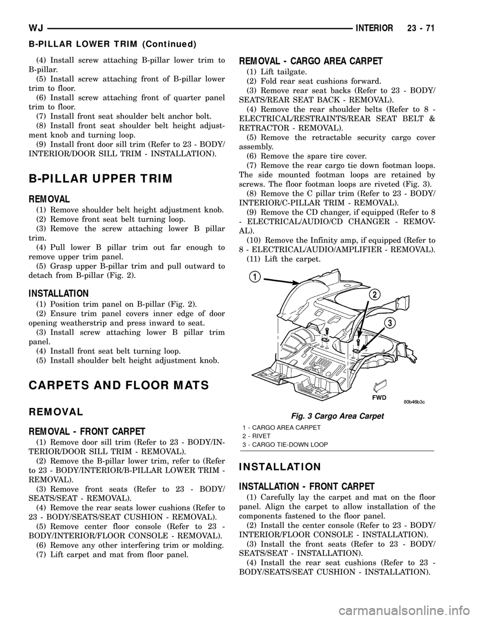
(7) Remove the rear cargo tie down footman loops.
The side mounted footman loops are retained by
screws. The floor footman loops are riveted (Fig. 3).
(8) Remove the C pillar trim (Refer to 23 - BODY/
INTERIOR/C-PILLAR TRIM - REMOVAL).
(9) Remove the CD changer, if equipped (Refer to 8
- ELECTRICAL/AUDIO/CD CHANGER - REMOV-
AL).
(10) Remove the Infinity amp, if equipped (Refer to
8 - ELECTRICAL/AUDIO/AMPLIFIER - REMOVAL).
(11) Lift the carpet.
INSTALLATION
INSTALLATION - FRONT CARPET
(1) Carefully lay the carpet and mat on the floor
panel. Align the carpet to allow installation of the
components fastened to the floor panel.
(2) Install the center console (Refer to 23 - BODY/
INTERIOR/FLOOR CONSOLE - INSTALLATION).
(3) Install the front seats (Refer to 23 - BODY/
SEATS/SEAT - INSTALLATION).
(4) Install the rear seat cushions (Refer to 23 -
BODY/SEATS/SEAT CUSHION - INSTALLATION).
Fig. 3 Cargo Area Carpet
1 - CARGO AREA CARPET
2 - RIVET
3 - CARGO TIE-DOWN LOOP
WJINTERIOR 23 - 71
B-PILLAR LOWER TRIM (Continued)
Page 1945 of 2199
(5) Install the lower B pillar trim (Refer to 23 -
BODY/INTERIOR/B-PILLAR LOWER TRIM -
INSTALLATION).
(6) Install the door sill trim (Refer to 23 - BODY/
INTERIOR/DOOR SILL TRIM - INSTALLATION).
(7) Install any other moldings or trim panels
removed.
INSTALLATION - CARGO AREA CARPET
(1) Thoroughly clean the area with Mopar Super
Kleent, or equivalent.
(2) Lay the new carpet in.
(3) Install the ªCº pillar trim (Refer to 23 - BODY/
INTERIOR/C-PILLAR TRIM - INSTALLATION).
(4) Install the CD changer, if equipped (Refer to 8 -
ELECTRICAL/AUDIO/CD CHANGER - INSTALLA-
TION).
(5) Install the footman loops (Fig. 3).
(6) Install the rear shoulder belts (Refer to 8 -
ELECTRICAL/RESTRAINTS/REAR SEAT BELT &
RETRACTOR - INSTALLATION).
(7) Install the rear seat backs (Refer to 23 -
BODY/SEATS/REAR SEAT BACK - INSTALLA-
TION).
(8) Install the Infinity amp, if equipped (Refer to 8
- ELECTRICAL/AUDIO/AMPLIFIER - INSTALLA-
TION).
(9) Install the spare tire cover.
(10) Install the retractable security cover.
COWL TRIM
REMOVAL
(1) Remove front door sill trim (Refer to 23 -
BODY/INTERIOR/DOOR SILL TRIM - REMOVAL).
(2) Remove screws attaching cowl trim to floor.
(3) Remove plastic nut.
(4) Grasp cowl trim and pull outward to separate
from clip.
(5) Separate cowl trim from vehicle.
INSTALLATION
(1) Position cowl trim and press into place.
(2) Install screws attaching cowl trim to floor.
(3) Install plastic nut.
(4) Install front door sill trim (Refer to 23 - BODY/
INTERIOR/DOOR SILL TRIM - INSTALLATION).
C-PILLAR TRIM
REMOVAL
(1) Remove rear shoulder belt turning loop.
(2) Remove rear shoulder belt height adjustment
knob.
(3) Remove screws attaching quarter panel trim.
(4) Pull quarter panel trim outward as necessary.
(5) Grasp C-pillar upper trim and pull outward to
disengage from C-pillar (Fig. 4).
(6) Route rear shoulder belt through access hole.
(7) Separate C-pillar upper trim from vehicle.
INSTALLATION
(1) Position C-pillar upper trim at C-pillar (Fig. 4).
(2) Route rear shoulder belt through access hole.
(3) Press C-pillar upper trim onto C-pillar.
(4) Press quarter panel trim into place as neces-
sary.
(5) Ensure front edge of trim is covered by weath-
erstrip.
(6) Install screws attaching quarter panel trim.
(7) Install rear shoulder belt height adjustment
knob.
(8) Install rear shoulder belt turning loop.
23 - 72 INTERIORWJ
CARPETS AND FLOOR MATS (Continued)
Page 1948 of 2199
D-PILLAR TRIM
REMOVAL
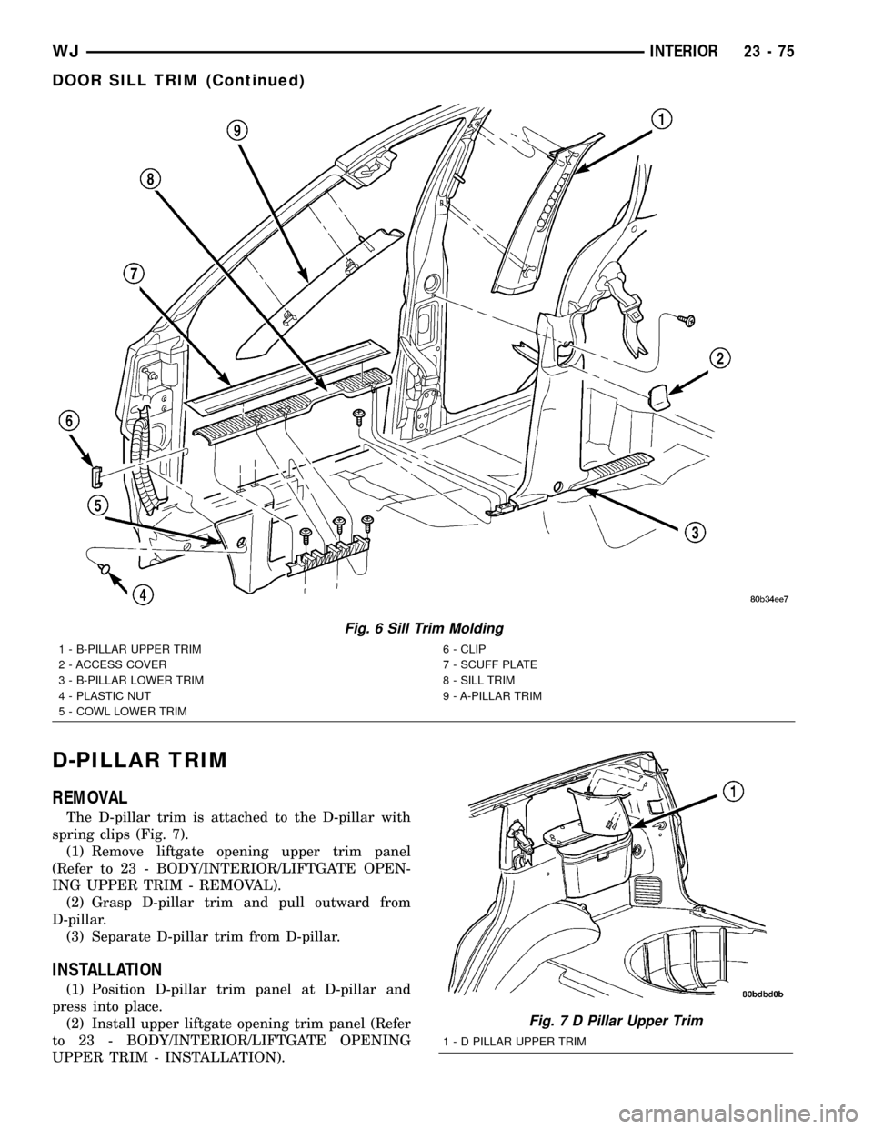
The D-pillar trim is attached to the D-pillar with
spring clips (Fig. 7).
(1) Remove liftgate opening upper trim panel
(Refer to 23 - BODY/INTERIOR/LIFTGATE OPEN-
ING UPPER TRIM - REMOVAL).
(2) Grasp D-pillar trim and pull outward from
D-pillar.
(3) Separate D-pillar trim from D-pillar.
INSTALLATION
(1) Position D-pillar trim panel at D-pillar and
press into place.
(2) Install upper liftgate opening trim panel (Refer
to 23 - BODY/INTERIOR/LIFTGATE OPENING
UPPER TRIM - INSTALLATION).
Fig. 6 Sill Trim Molding
1 - B-PILLAR UPPER TRIM
2 - ACCESS COVER
3 - B-PILLAR LOWER TRIM
4 - PLASTIC NUT
5 - COWL LOWER TRIM6 - CLIP
7 - SCUFF PLATE
8 - SILL TRIM
9 - A-PILLAR TRIM
Fig. 7 D Pillar Upper Trim
1 - D PILLAR UPPER TRIM
WJINTERIOR 23 - 75
DOOR SILL TRIM (Continued)
Page 1950 of 2199
HEADLINER
REMOVAL
CAUTION: The headliner is a one-piece, molded
component. It has limited flexibility and must not be
bent. Damage may possibly result.
(1) Record radio presets and disconnect negative
battery cable.
(2) Remove A pillar trim moldings (Refer to 23 -
BODY/INTERIOR/A-PILLAR TRIM - REMOVAL).
(3) Remove B pillar upper trim moldings (Refer to
23 - BODY/INTERIOR/B-PILLAR UPPER TRIM -
REMOVAL).
(4) Remove C pillar trim moldings (Refer to 23 -
BODY/INTERIOR/C-PILLAR TRIM - REMOVAL).
(5) Remove D pillar trim molding (Refer to 23 -
BODY/INTERIOR/D-PILLAR TRIM - REMOVAL).
(6) Remove the sun visors (Refer to 23 - BODY/IN-
TERIOR/SUN VISOR - REMOVAL).
(7) Disconnect the vanity lamp electrical connector.
(8) Remove assist handles from roof rails (Refer to
23 - BODY/INTERIOR/ASSIST HANDLE - REMOV-
AL).
(9) Remove dome lamp and overhead console, if
equipped.
(10) Remove rear cargo/dome lamp.
(11) Remove sun roof pinch welt, if equipped.
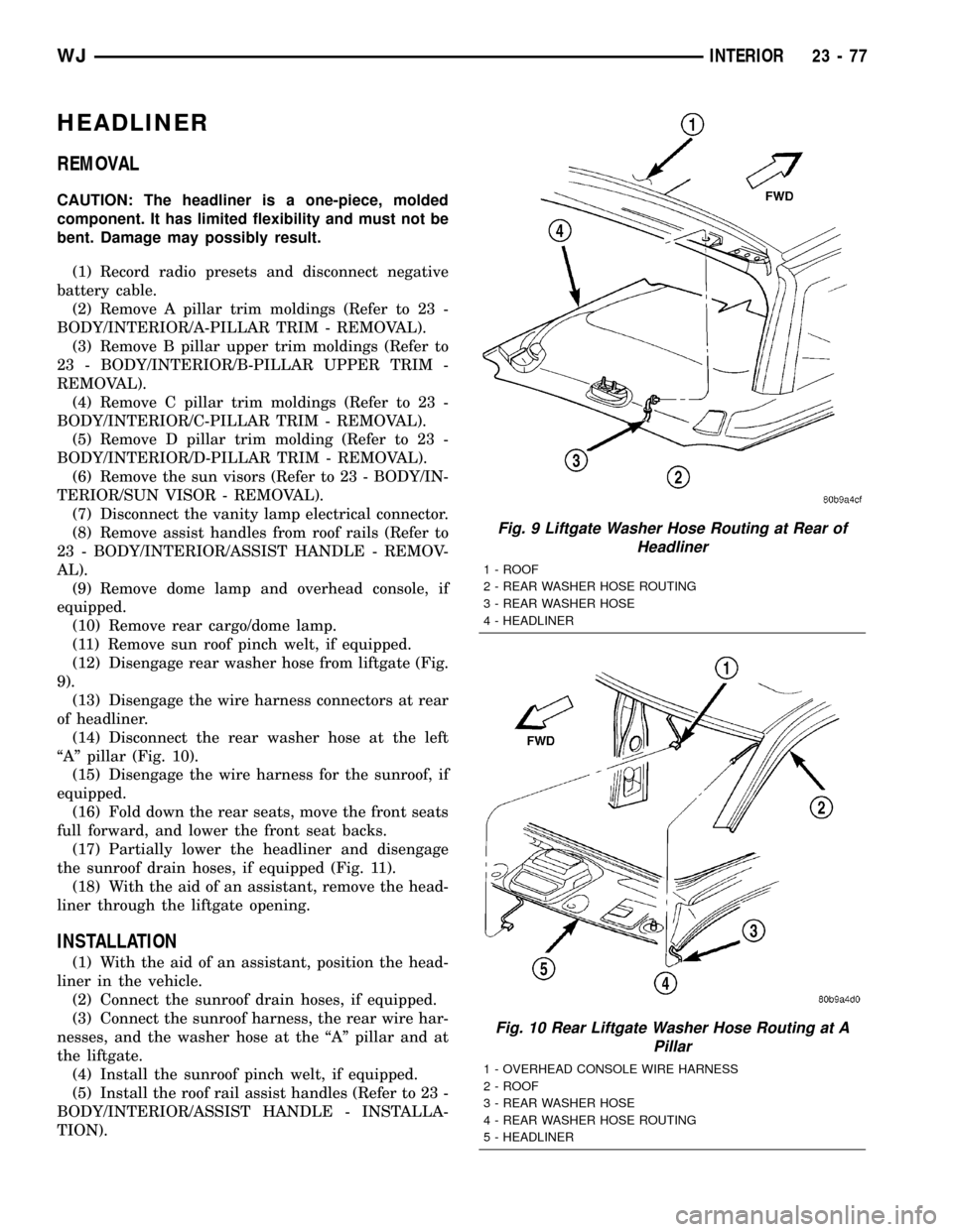
(12) Disengage rear washer hose from liftgate (Fig.
9).
(13) Disengage the wire harness connectors at rear
of headliner.
(14) Disconnect the rear washer hose at the left
ªAº pillar (Fig. 10).
(15) Disengage the wire harness for the sunroof, if
equipped.
(16) Fold down the rear seats, move the front seats
full forward, and lower the front seat backs.
(17) Partially lower the headliner and disengage
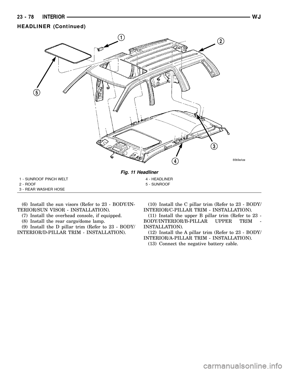
the sunroof drain hoses, if equipped (Fig. 11).
(18) With the aid of an assistant, remove the head-
liner through the liftgate opening.
INSTALLATION
(1) With the aid of an assistant, position the head-
liner in the vehicle.
(2) Connect the sunroof drain hoses, if equipped.
(3) Connect the sunroof harness, the rear wire har-
nesses, and the washer hose at the ªAº pillar and at
the liftgate.
(4) Install the sunroof pinch welt, if equipped.
(5) Install the roof rail assist handles (Refer to 23 -
BODY/INTERIOR/ASSIST HANDLE - INSTALLA-
TION).
Fig. 9 Liftgate Washer Hose Routing at Rear of
Headliner
1 - ROOF
2 - REAR WASHER HOSE ROUTING
3 - REAR WASHER HOSE
4 - HEADLINER
Fig. 10 Rear Liftgate Washer Hose Routing at A
Pillar
1 - OVERHEAD CONSOLE WIRE HARNESS
2 - ROOF
3 - REAR WASHER HOSE
4 - REAR WASHER HOSE ROUTING
5 - HEADLINER
WJINTERIOR 23 - 77
Page 1951 of 2199
(6) Install the sun visors (Refer to 23 - BODY/IN-
TERIOR/SUN VISOR - INSTALLATION).
(7) Install the overhead console, if equipped.
(8) Install the rear cargo/dome lamp.
(9) Install the D pillar trim (Refer to 23 - BODY/
INTERIOR/D-PILLAR TRIM - INSTALLATION).(10) Install the C pillar trim (Refer to 23 - BODY/
INTERIOR/C-PILLAR TRIM - INSTALLATION).
(11) Install the upper B pillar trim (Refer to 23 -
BODY/INTERIOR/B-PILLAR UPPER TRIM -
INSTALLATION).
(12) Install the A pillar trim (Refer to 23 - BODY/
INTERIOR/A-PILLAR TRIM - INSTALLATION).
(13) Connect the negative battery cable.
Fig. 11 Headliner
1 - SUNROOF PINCH WELT
2 - ROOF
3 - REAR WASHER HOSE4 - HEADLINER
5 - SUNROOF
23 - 78 INTERIORWJ
HEADLINER (Continued)
Page 1952 of 2199
LIFTGATE OPENING UPPER
TRIM
REMOVAL
The upper liftgate opening trim is held on with
spring clips.
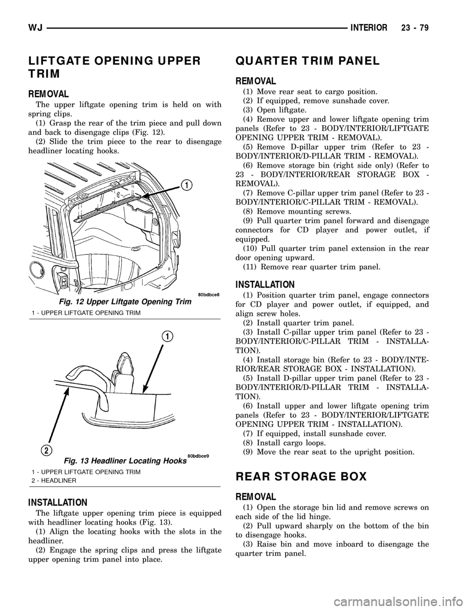
(1) Grasp the rear of the trim piece and pull down
and back to disengage clips (Fig. 12).
(2) Slide the trim piece to the rear to disengage
headliner locating hooks.
INSTALLATION
The liftgate upper opening trim piece is equipped
with headliner locating hooks (Fig. 13).
(1) Align the locating hooks with the slots in the
headliner.
(2) Engage the spring clips and press the liftgate
upper opening trim panel into place.
QUARTER TRIM PANEL
REMOVAL
(1) Move rear seat to cargo position.
(2) If equipped, remove sunshade cover.
(3) Open liftgate.
(4) Remove upper and lower liftgate opening trim
panels (Refer to 23 - BODY/INTERIOR/LIFTGATE
OPENING UPPER TRIM - REMOVAL).
(5) Remove D-pillar upper trim (Refer to 23 -
BODY/INTERIOR/D-PILLAR TRIM - REMOVAL).
(6) Remove storage bin (right side only) (Refer to
23 - BODY/INTERIOR/REAR STORAGE BOX -
REMOVAL).
(7) Remove C-pillar upper trim panel (Refer to 23 -
BODY/INTERIOR/C-PILLAR TRIM - REMOVAL).
(8) Remove mounting screws.
(9) Pull quarter trim panel forward and disengage
connectors for CD player and power outlet, if
equipped.
(10) Pull quarter trim panel extension in the rear
door opening upward.
(11) Remove rear quarter trim panel.
INSTALLATION
(1) Position quarter trim panel, engage connectors
for CD player and power outlet, if equipped, and
align screw holes.
(2) Install quarter trim panel.
(3) Install C-pillar upper trim panel (Refer to 23 -
BODY/INTERIOR/C-PILLAR TRIM - INSTALLA-
TION).
(4) Install storage bin (Refer to 23 - BODY/INTE-
RIOR/REAR STORAGE BOX - INSTALLATION).
(5) Install D-pillar upper trim panel (Refer to 23 -
BODY/INTERIOR/D-PILLAR TRIM - INSTALLA-
TION).
(6) Install upper and lower liftgate opening trim
panels (Refer to 23 - BODY/INTERIOR/LIFTGATE
OPENING UPPER TRIM - INSTALLATION).
(7) If equipped, install sunshade cover.
(8) Install cargo loops.
(9) Move the rear seat to the upright position.
REAR STORAGE BOX
REMOVAL
(1) Open the storage bin lid and remove screws on
each side of the lid hinge.
(2) Pull upward sharply on the bottom of the bin
to disengage hooks.
(3) Raise bin and move inboard to disengage the
quarter trim panel.
Fig. 12 Upper Liftgate Opening Trim
1 - UPPER LIFTGATE OPENING TRIM
Fig. 13 Headliner Locating Hooks
1 - UPPER LIFTGATE OPENING TRIM
2 - HEADLINER
WJINTERIOR 23 - 79
Page 1954 of 2199
PAINT
TABLE OF CONTENTS
page page
PAINT
SPECIFICATIONS - PAINT CODES..........81
PAINT CODE
DESCRIPTION.........................81
BASE COAT/CLEAR COAT FINISH
DESCRIPTION.........................81PAINT TOUCH-UP
DESCRIPTION.........................82
FINESSE SANDING/BUFFING & POLISHING
DESCRIPTION.........................82
PAINT
SPECIFICATIONS - PAINT CODES
EXTERIOR COLORS
EXTERIOR COLOR DAIMLERCHRYSLER
CODE
Dark Garnet Red
PearlcoatXRV
Inferno Red Tinted
PearlcoatWEL
Woodland Brown Satin
GlowYUB
Onyx Green Pearlcoat YJR
Steel Blue Pearlcoat XBQ
Patriot Blue Pearlcoat WBT
Silverstone Metallic
ClearcoatXS5
Graphite Metallic
ClearcoatZDR
Black Clearcoat DX8
Stone White Clearcoat SW1
INTERIOR COLORS
INTERIOR COLOR DAIMLERCHRYSLER
CODE
Dark Slate Grey DV
Taupe L5
Sandstone T5
Dark Slate/Light Slate DB
LAREDO FASCIA/CLADDING COLORS
COLOR DAIMLERCHRYSLER
CODE
Dark Grey Metallic XS9
PAINT CODE
DESCRIPTION
Exterior vehicle body colors are identified on the
Body Code plate. The plate is located on the in the
engine compartment and attached to the top of the
right frame rail. Refer to the Introduction section at
the front of this manual for body code plate descrip-
tion. The paint code is also identified on the Vehicle
Safety Certification Label which is located on the
drivers door shut face. The first digit of the paint
code listed on the vehicle indicates the sequence of
application, i.e.: P = primary coat, Q = secondary
coat.
BASE COAT/CLEAR COAT
FINISH
DESCRIPTION
The original equipment finish is a multi-step pro-
cess that involves cleaning, electrodeposition (e-coat),
base coat, and clear coat steps. Additionally, selected
areas of the vehicle may be coated with an anti-chip
finish.
WJPAINT 23 - 81
Page 1955 of 2199
PAINT TOUCH-UP
DESCRIPTION
When a painted metal surface has been scratched
or chipped, it should be touched-up as soon as possi-
ble to avoid corrosion. For best results, use Mopart
Scratch Filler/Primer, Touch-Up Paints and Clear Top
Coat. Refer to Introduction group of this manual for
Body Code Plate information.
WARNING: USE AN OSHA APPROVED BREATHING
FILTER WHEN SPRAYING PAINT OR SOLVENTS IN
A CONFINED AREA. PERSONAL INJURY CAN
RESULT.
OPERATION
(1) Scrape loose paint and corrosion from inside
scratch or chip.
(2) Clean affected area with MopartTar/Road Oil
Remover, and allow to dry.
(3) Fill the inside of the scratch or chip with a coat
of filler/primer. Do not overlap primer onto good sur-
face finish. The applicator brush should be wet
enough to puddle-fill the defect without running. Do
not stroke brush applicator on body surface. Allow
the filler/primer to dry hard.
(4) Cover the filler/primer with color touch-up
paint. Do not overlap touch-up color onto the original
color coat around the scratch or chip. Butt the new
color to the original color, if possible. Do not stroke
applicator brush on body surface. Allow touch-up
paint to dry hard.
(5) On vehicles without clear coat, the touch-up
color can be lightly finesse sanded (1500 grit) and
polished with rubbing compound.
(6) On vehicles with clear coat, apply clear top coat
to touch-up paint with the same technique as
described in Step 4. Allow clear top coat to dry hard.
If desired, Step 5 can be performed on clear top coat.
WARNING: AVOID PROLONGED SKIN CONTACT
WITH PETROLEUM OR ALCOHOL ± BASED CLEAN-
ING SOLVENTS. PERSONAL INJURY CAN RESULT.
AVOID PROLONGED SKIN CONTACT WITH PETRO-
LEUM OR ALCOHOL ± BASED CLEANING SOL-
VENTS. PERSONAL INJURY CAN RESULT.
FINESSE SANDING/BUFFING &
POLISHING
DESCRIPTION
CAUTION: Do not remove more than .5 mils of
clearcoat finish, if equipped. Base coat paint must
retain clear coat for durability.
Use a Paint Thickness Gauge #PR-ETG-2X or equiv-
alent to determine film thickness before and after
the repair.
Minor acid etching, orange peel, or smudging in
clearcoat or single-stage finishes can be reduced with
light finesse sanding, hand buffing, and polishing.If
the finish has been finesse sanded in the past,
it cannot be repeated. Finesse sanding opera-
tion should be performed by a trained automo-
tive paint technician.
23 - 82 PAINTWJ
Page 1957 of 2199
FRONT HEADREST SLEEVE
REMOVAL
(1) Remove head restraint (Refer to 23 - BODY/
SEATS/FRONT HEADREST - REMOVAL).
(2) Remove seat back cover (Refer to 23 - BODY/
SEATS/FRONT SEAT BACK COVER - REMOVAL).
(3) Remove hog rings attaching cushion pad to
seat back frame (Fig. 2).
(4) Remove cushion pad from seat back frame.
(5) Rotate head restraint sleeve 1/4 turn counter-
clockwise to release retaining tab.
(6) Pull sleeve from seat back frame (Fig. 3).
INSTALLATION
(1) Position sleeve in seat back frame.
(2) Rotate head restraint sleeve 1/4 turn clockwise
to engage retaining tab.
(3) Install cushion pad onto seat back frame.
(4) Install hog rings attaching cushion pad to seat
back frame.
(5)
Install seat back cover (Refer to 23 - BODY/
SEATS/FRONT SEAT BACK COVER - INSTALLATION).
(6) Install head restraint (Refer to 23 - BODY/
SEATS/FRONT HEADREST - INSTALLATION).
FRONT SEAT
REMOVAL
(1) Move seat to full rearward position.(2) Remove front bolts attaching seat to floor pan
(Fig. 4).
(3) Move seat to full forward position.
(4) Using a trim stick, pry cover from seat track
(power seat only).
(5) Remove rear bolts attaching seat to floor pan.
(6) If equipped, disconnect power seat wire har-
ness connector.
(7) Remove seat from vehicle.
Fig. 2 Cushion Pad
1 - HOG RING
2 - SEAT BACK CUSHION PAD
Fig. 3 Head Restraint Sleeve
1 - HEAD RESTRAINT SLEEVE
2 - SEAT BACK FRAME
3 - RETAINING TAB
Fig. 4 Front Bucket Seat
1 - POWER BUCKET SEAT
2 - FLOOR PAN
3 - SEAT TRACK COVER
23 - 84 SEATSWJ