Engine JEEP GRAND CHEROKEE 2002 WJ / 2.G Workshop Manual
[x] Cancel search | Manufacturer: JEEP, Model Year: 2002, Model line: GRAND CHEROKEE, Model: JEEP GRAND CHEROKEE 2002 WJ / 2.GPages: 2199, PDF Size: 76.01 MB
Page 1876 of 2199

(2) Apply silicone lubricant to a cloth and wipe it
on door seals to avoid over-spray that can soil pas-
senger's clothing.
(3) Before applying lubricant, the component
should be wiped clean. After lubrication, any excess
lubricant should be removed.
(4) The hood latch, latch release mechanism, latch
striker, and safety latch should be lubricated period-
ically.
(5) The door lock cylinders should be lubricated
twice each year (preferably autumn and spring).
(a) Spray a small amount of lock cylinder lubri-
cant directly into the lock cylinder.
(b) Apply a small amount to the key and insert
it into the lock cylinder.
(c) Rotate it to the locked position and then back
to the unlocked position several times.(d) Remove the key. Wipe the lubricant from it
with a clean cloth to avoid soiling of clothing.
STANDARD PROCEDURE - DRILLING AND
WELDING
When holes must be drilled or punched in an inner
body panel, verify depth of space to the outer body
panel, electrical wiring, or other components. Dam-
age to vehicle can result.
Do not weld exterior panels unless combustible
material on the interior of vehicle is removed from
the repair area. Fire or hazardous conditions, can
result.
Always have a fire extinguisher ready for use when
welding.
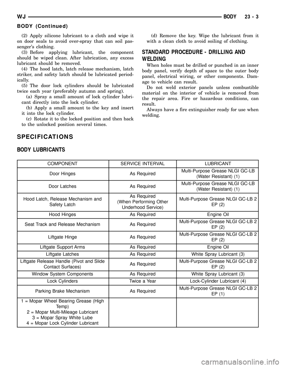
SPECIFICATIONS
BODY LUBRICANTS
COMPONENT SERVICE INTERVAL LUBRICANT
Door Hinges As RequiredMulti-Purpose Grease NLGI GC-LB
(Water Resistant) (1)
Door Latches As RequiredMulti-Purpose Grease NLGI GC-LB
(Water Resistant) (1)
Hood Latch, Release Mechanism and
Safety LatchAs Required
(When Performing Other
Underhood Service)Multi-Purpose Grease NLGI GC-LB 2
EP (2)
Hood Hinges As Required Engine Oil
Seat Track and Release Mechanism As RequiredMulti-Purpose Grease NLGI GC-LB 2
EP (2)
Liftgate Hinge As RequiredMulti-Purpose Grease NLGI GC-LB 2
EP (2)
Liftgate Support Arms As Required Engine Oil
Liftgate Latches As Required White Spray Lubricant (3)
Liftgate Release Handle (Pivot and Slide
Contact Surfaces)As RequiredMulti-Purpose Grease NLGI GC-LB 2
EP (2)
Window System Components As Required White Spray Lubricant (3)
Lock Cylinders Twice a Year Lock-Cylinder Lubricant (4)
Parking Brake Mechanism As RequiredMulti-Purpose Grease NLGI GC-LB 2
EP (1)
1 = Mopar Wheel Bearing Grease (High
Temp)
2 = Mopar Multi-Mileage Lubricant
3 = Mopar Spray White Lube
4 = Mopar Lock Cylinder Lubricant
WJBODY 23 - 3
BODY (Continued)
Page 1902 of 2199

(8) Loosen screw under hood hinge, attaching
fender to engine compartment rail.
(9) Remove screws attaching fender to engine com-
partment rail (Fig. 7).
(10) Right fender only:
(a) If equipped, remove radio antenna.
(11) Separate fender from body.
INSTALLATION
(1) Position fender on body.
(2) Right fender only:
(a) If equipped, install radio antenna.
(3) Install all screws finger-tight.
(4) Align fender with adjacent body panels and
wax crayon reference marks.
(5) Tighten all screws.
(6) Install inner fender liner.
FUEL FILL DOOR
REMOVAL
(1) Open the fuel filler door.
(2) Remove the screws attaching the door to the
quarter panel (Fig. 8).
(3) Remove the door from the panel.
INSTALLATION
(1) Position the fuel filler door on the quarter
panel with the screw holes aligned.(2) Install the screws attaching the fuel filler door
to the quarter panel.
GRILLE
REMOVAL
(1) Remove fascia, refer to (Refer to 13 - FRAMES
& BUMPERS/BUMPERS/FRONT FASCIA - REMOV-
AL).
(2) Disengage retainers attaching grille insert to
grille/fascia.
(3) Separate grille insert from grille/fascia (Fig. 9).
INSTALLATION
(1) Position grille insert in grille/fascia (Fig. 9).
(2) Engage retainers attaching grille insert to
grille/fascia.
Fig. 7 Upper Fender Mounting
1 - FENDER
2 - BODY
Fig. 8 Fuel Filler Door
1 - FUEL FILL DOOR
Fig. 9 Grille Insert
1 - GRILLE/FASCIA
2 - INSERT
WJEXTERIOR 23 - 29
FRONT FENDER (Continued)
Page 1908 of 2199

LATCH RELEASE CABLE
REMOVAL
(1) Disconnect cable from hood latch (Fig. 3).
(2) Disconnect cable from retaining clips on left
inner fender panel.
(3) Remove left cowl side trim panel.
(4) Remove fasteners attaching cable bracket to
cowl side panel (Fig. 4).
(5) Route cable through dash panel and remove it
from under instrument panel.
INSTALLATION
(1) Route cable through hole in dash panel into
engine compartment.
(2) Pull cable forward and seat grommet in dash
panel.
(3) Position cable bracket on cowl side panel and
install fasteners (Fig. 4).
(4) Install left cowl side trim panel.
(5) Route and install cable in retaining clips on left
inner fender panel.
(6) Connect cable to hood latch (Fig. 3).
Fig. 3 Hood Latch
1 - HOOD LATCH
2 - HOOD RELEASE CABLE
Fig. 4 Hood Release Cable
1 - LOWER COWL
2 - HOOD RELEASE CABLE
3 - RELEASE HANDLE
WJHOOD 23 - 35
Page 1954 of 2199

PAINT
TABLE OF CONTENTS
page page
PAINT
SPECIFICATIONS - PAINT CODES..........81
PAINT CODE
DESCRIPTION.........................81
BASE COAT/CLEAR COAT FINISH
DESCRIPTION.........................81PAINT TOUCH-UP
DESCRIPTION.........................82
FINESSE SANDING/BUFFING & POLISHING
DESCRIPTION.........................82
PAINT
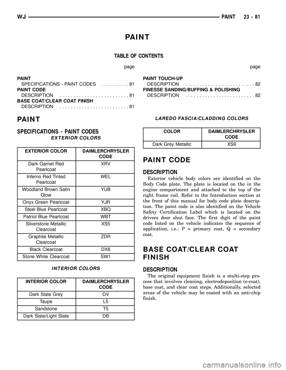
SPECIFICATIONS - PAINT CODES
EXTERIOR COLORS
EXTERIOR COLOR DAIMLERCHRYSLER
CODE
Dark Garnet Red
PearlcoatXRV
Inferno Red Tinted
PearlcoatWEL
Woodland Brown Satin
GlowYUB
Onyx Green Pearlcoat YJR
Steel Blue Pearlcoat XBQ
Patriot Blue Pearlcoat WBT
Silverstone Metallic
ClearcoatXS5
Graphite Metallic
ClearcoatZDR
Black Clearcoat DX8
Stone White Clearcoat SW1
INTERIOR COLORS
INTERIOR COLOR DAIMLERCHRYSLER
CODE
Dark Slate Grey DV
Taupe L5
Sandstone T5
Dark Slate/Light Slate DB
LAREDO FASCIA/CLADDING COLORS
COLOR DAIMLERCHRYSLER
CODE
Dark Grey Metallic XS9
PAINT CODE
DESCRIPTION
Exterior vehicle body colors are identified on the
Body Code plate. The plate is located on the in the
engine compartment and attached to the top of the
right frame rail. Refer to the Introduction section at
the front of this manual for body code plate descrip-
tion. The paint code is also identified on the Vehicle
Safety Certification Label which is located on the
drivers door shut face. The first digit of the paint
code listed on the vehicle indicates the sequence of
application, i.e.: P = primary coat, Q = secondary
coat.
BASE COAT/CLEAR COAT
FINISH
DESCRIPTION
The original equipment finish is a multi-step pro-
cess that involves cleaning, electrodeposition (e-coat),
base coat, and clear coat steps. Additionally, selected
areas of the vehicle may be coated with an anti-chip
finish.
WJPAINT 23 - 81
Page 1987 of 2199

OPENING DIMENSIONS
SPECIFICATIONS - BODY OPENING
DIMENSIONS
DESCRIPTION FIGURE
WINDSHIELD AND
FRONT DOOR
OPENING3
REAR DOOR AND
QUARTER GLASS
OPENING4
LIFTGATE OPENING
AND ENGINE
COMPARTMENT5
23 - 114 BODY STRUCTUREWJ
Page 1990 of 2199

Fig. 5 LIFTGATE OPENING AND ENGINE COMPARTMENT
WJBODY STRUCTURE 23 - 117
OPENING DIMENSIONS (Continued)
Page 2027 of 2199

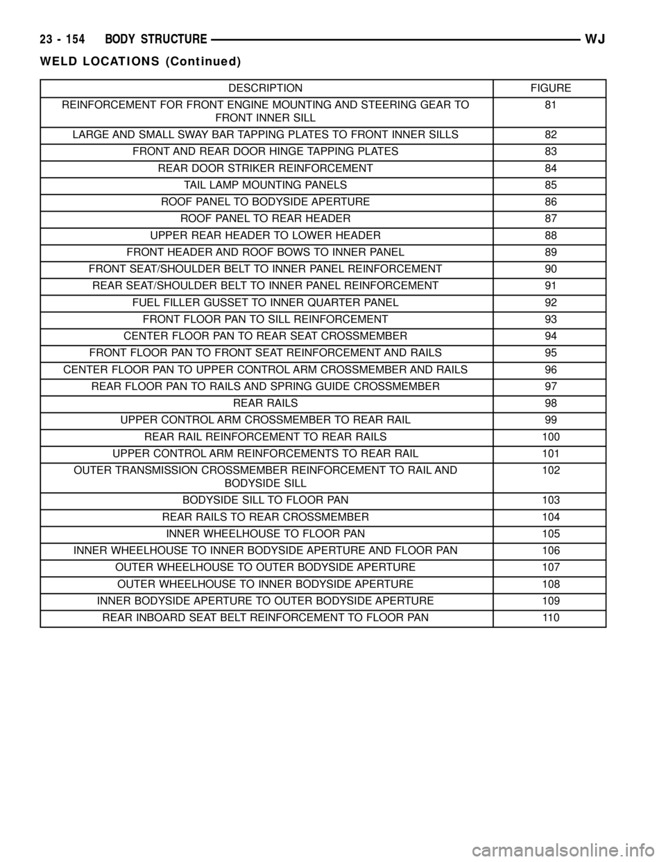
DESCRIPTION FIGURE
REINFORCEMENT FOR FRONT ENGINE MOUNTING AND STEERING GEAR TO
FRONT INNER SILL81
LARGE AND SMALL SWAY BAR TAPPING PLATES TO FRONT INNER SILLS 82
FRONT AND REAR DOOR HINGE TAPPING PLATES 83
REAR DOOR STRIKER REINFORCEMENT 84
TAIL LAMP MOUNTING PANELS 85
ROOF PANEL TO BODYSIDE APERTURE 86
ROOF PANEL TO REAR HEADER 87
UPPER REAR HEADER TO LOWER HEADER 88
FRONT HEADER AND ROOF BOWS TO INNER PANEL 89
FRONT SEAT/SHOULDER BELT TO INNER PANEL REINFORCEMENT 90
REAR SEAT/SHOULDER BELT TO INNER PANEL REINFORCEMENT 91
FUEL FILLER GUSSET TO INNER QUARTER PANEL 92
FRONT FLOOR PAN TO SILL REINFORCEMENT 93
CENTER FLOOR PAN TO REAR SEAT CROSSMEMBER 94
FRONT FLOOR PAN TO FRONT SEAT REINFORCEMENT AND RAILS 95
CENTER FLOOR PAN TO UPPER CONTROL ARM CROSSMEMBER AND RAILS 96
REAR FLOOR PAN TO RAILS AND SPRING GUIDE CROSSMEMBER 97
REAR RAILS 98
UPPER CONTROL ARM CROSSMEMBER TO REAR RAIL 99
REAR RAIL REINFORCEMENT TO REAR RAILS 100
UPPER CONTROL ARM REINFORCEMENTS TO REAR RAIL 101
OUTER TRANSMISSION CROSSMEMBER REINFORCEMENT TO RAIL AND
BODYSIDE SILL102
BODYSIDE SILL TO FLOOR PAN 103
REAR RAILS TO REAR CROSSMEMBER 104
INNER WHEELHOUSE TO FLOOR PAN 105
INNER WHEELHOUSE TO INNER BODYSIDE APERTURE AND FLOOR PAN 106
OUTER WHEELHOUSE TO OUTER BODYSIDE APERTURE 107
OUTER WHEELHOUSE TO INNER BODYSIDE APERTURE 108
INNER BODYSIDE APERTURE TO OUTER BODYSIDE APERTURE 109
REAR INBOARD SEAT BELT REINFORCEMENT TO FLOOR PAN 110
23 - 154 BODY STRUCTUREWJ
WELD LOCATIONS (Continued)
Page 2053 of 2199

Fig. 81 REINFORCEMENT FOR FRONT ENGINE MOUNTING AND STEERING GEAR TO FRONT INNER SILL
23 - 180 BODY STRUCTUREWJ
WELD LOCATIONS (Continued)
Page 2078 of 2199

HEATING & AIR CONDITIONING
TABLE OF CONTENTS
page page
HEATING & AIR CONDITIONING
DESCRIPTION
DESCRIPTION - COOLING SYSTEM
REQUIREMENTS.......................1
DESCRIPTION - HEATER AND AIR
CONDITIONER........................1
DESCRIPTION - REFRIGERANT SYSTEM
SERVICE PORT........................1
OPERATION
OPERATION - HEATER AND AIR
CONDITIONER........................2
OPERATION - REFRIGERANT SYSTEM
SERVICE PORT........................2DIAGNOSIS AND TESTING
DIAGNOSIS AND TESTING - A/C
PERFORMANCE.......................2
DIAGNOSIS AND TESTING - HEATER
PERFORMANCE.......................6
STANDARD PROCEDURE - DIODE
REPLACEMENT.......................6
SPECIFICATIONS
A/C APPLICATION TABLE................7
TORQUE SPECIFICATIONS..............8
CONTROLS.............................9
DISTRIBUTION..........................36
PLUMBING.............................51
HEATING & AIR
CONDITIONING
DESCRIPTION
DESCRIPTION - COOLING SYSTEM
REQUIREMENTS
To maintain the performance level of the heating-
air conditioning system, the engine cooling system
must be properly maintained. The use of a bug
screen is not recommended. Any obstructions in front
of the radiator or condenser will reduce the perfor-
mance of the air conditioning and engine cooling sys-
tems.
The engine cooling system includes the heater core
and the heater hoses. Refer to Cooling for more infor-
mation before opening, or attempting any service to
the engine cooling system.
DESCRIPTION - HEATER AND AIR
CONDITIONER
A manual temperature control type heating-air
conditioning system is standard factory-installed
equipment on this model. An electronically controlled
Automatic Zone Control (AZC) type heating-air con-
ditioning system is an available factory-installed
option.
All vehicles are equipped with a common HVAC
housing assembly (Fig. 1). The system combines air
conditioning, heating, and ventilating capabilities in
a single unit housing mounted under the instrument
panel.DESCRIPTION - REFRIGERANT SYSTEM
SERVICE PORT
The two refrigerant system service ports are used
to charge, recover/recycle, evacuate, and test the air
conditioning refrigerant system. Unique service port
coupler sizes are used on the R-134a system to
ensure that the refrigerant system is not accidentally
contaminated by the use of the wrong refrigerant
(R-12), or refrigerant system service equipment.
Fig. 1 Blend-Air HVAC System - (typical)
1 - Blend Door
2 - Expansion Valve
3 - Evaporator Core
4 - Blower Assembly
5 - Recirculation Door
6 - Evaporator Probe
7 - Heater Core
8 - Heat/Defrost Door
9 - Panel/Defrost Door
WJHEATING & AIR CONDITIONING 24 - 1
Page 2079 of 2199

OPERATION
OPERATION - HEATER AND AIR CONDITIONER
Outside fresh air enters the vehicle through the
cowl top opening at the base of the windshield, and
passes through a plenum chamber to the HVAC sys-
tem blower housing. Air flow velocity can then be
adjusted with the blower motor speed selector switch
on the a/c heater control panel. The air intake open-
ings must be kept free of snow, ice, leaves, and other
obstructions for the HVAC system to receive a suffi-
cient volume of outside air.
It is also important to keep the air intake openings
clear of debris because leaf particles and other debris
that is small enough to pass through the cowl ple-
num screen can accumulate within the HVAC hous-
ing. The closed, warm, damp and dark environment
created within the HVAC housing is ideal for the
growth of certain molds, mildews and other fungi.
Any accumulation of decaying plant matter provides
an additional food source for fungal spores, which
enter the housing with the fresh air. Excess debris,
as well as objectionable odors created by decaying
plant matter and growing fungi can be discharged
into the passenger compartment during HVAC sys-
tem operation.
Both the manual and AZC heater and air condi-
tioner are blend-air type systems. In a blend-air sys-
tem, a blend door controls the amount of
unconditioned air (or cooled air from the evaporator)
that is allowed to flow through, or around, the heater
core. A temperature control knob on the a/c heater
control panel determines the discharge air tempera-
ture by energizing the blend door actuator, which
operates the blend door. This allows an almost imme-
diate control of the output air temperature of the sys-
tem. The AZC system will have separate blend doors
and temperature controls for each front seat occu-
pant.
The mode control knob on the a/c heater control
panel is used to direct the conditioned air to the
selected system outlets. On manual temperature con-
trol systems, the mode control knob switches engine
vacuum to control the mode doors, which are oper-
ated by vacuum actuators. On AZC systems, the
mode control knob switches electrical current to con-
trol the mode doors, which are operated by electronic
actuators.
The outside air intake can be shut off on manual
temperature control systems by selecting the Recircu-
lation Mode with the mode control knob. The outside
air intake can be shut off on Automatic Zone Control
(AZC) type system by pushing the Recirculation
Mode button. This will operate the recirculation door
that closes off the outside fresh air intake and recir-
culates the air that is already inside the vehicle.The air conditioner for all models is designed for
the use of non-CFC, R-134a refrigerant. The air con-
ditioning system has an evaporator to cool and dehu-
midify the incoming air prior to blending it with the
heated air. This air conditioning system uses a ther-
mal expansion valve to meter refrigerant flow to the
evaporator coil. To maintain minimum evaporator
temperature and prevent evaporator freezing, the
system utilizes an evaporator thermister probe with
the appropriate operating logic located in the body
control module (BCM).
OPERATION - REFRIGERANT SYSTEM SERVICE
PORT
The high pressure service port is located on the liq-
uid line near the receiver/drier. The low pressure ser-
vice port is located on the suction line near the
evaporator at the rear of the engine compartment.
Each of the service ports has a threaded plastic
protective cap installed over it from the factory. After
servicing the refrigerant system, always reinstall
both of the service port caps.
DIAGNOSIS AND TESTING
DIAGNOSIS AND TESTING - A/C
PERFORMANCE
The air conditioning system is designed to provide
the passenger compartment with low temperature
and low specific humidity air. The evaporator, located
in the HVAC housing on the dash panel below the
instrument panel, is cooled to temperatures near the
freezing point. As warm damp air passes through the
cooled evaporator, the air transfers its heat to the
refrigerant in the evaporator and the moisture in the
air condenses on the evaporator fins. During periods
of high heat and humidity, an air conditioning sys-
tem will be more effective in the Recirculation Mode.
With the system in the Recirculation Mode, only air
from the passenger compartment passes through the
evaporator. As the passenger compartment air dehu-
midifies, the air conditioning system performance
levels improve.
Humidity has an important bearing on the tempera-
ture of the air delivered to the interior of the vehicle. It
is important to understand the effect that humidity has
on the performance of the air conditioning system.
When humidity is high, the evaporator has to perform a
double duty. It must lower the air temperature, and it
must lower the temperature of the moisture in the air
that condenses on the evaporator fins. Condensing the
moisture in the air transfers heat energy into the evap-
orator fins and tubing. This reduces the amount of heat
the evaporator can absorb from the air. High humidity
greatly reduces the ability of the evaporator to lower
the temperature of the air.
24 - 2 HEATING & AIR CONDITIONINGWJ
HEATING & AIR CONDITIONING (Continued)