Rear liftgate JEEP GRAND CHEROKEE 2002 WJ / 2.G Repair Manual
[x] Cancel search | Manufacturer: JEEP, Model Year: 2002, Model line: GRAND CHEROKEE, Model: JEEP GRAND CHEROKEE 2002 WJ / 2.GPages: 2199, PDF Size: 76.01 MB
Page 1192 of 2199
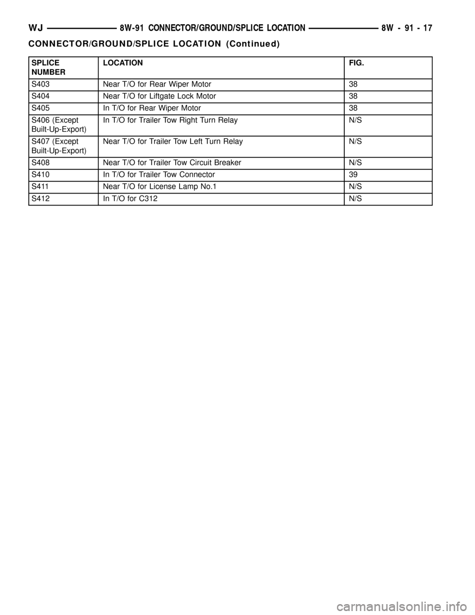
SPLICE
NUMBERLOCATION FIG.
S403 Near T/O for Rear Wiper Motor 38
S404 Near T/O for Liftgate Lock Motor 38
S405 In T/O for Rear Wiper Motor 38
S406 (Except
Built-Up-Export)In T/O for Trailer Tow Right Turn Relay N/S
S407 (Except
Built-Up-Export)Near T/O for Trailer Tow Left Turn Relay N/S
S408 Near T/O for Trailer Tow Circuit Breaker N/S
S410 In T/O for Trailer Tow Connector 39
S411 Near T/O for License Lamp No.1 N/S
S412 In T/O for C312 N/S
WJ8W-91 CONNECTOR/GROUND/SPLICE LOCATION 8W - 91 - 17
CONNECTOR/GROUND/SPLICE LOCATION (Continued)
Page 1241 of 2199

FuseandBatteryin the index in this service man-
ual for the location of additional service information
covering the ignition-off draw fuse and the battery.
FUSE COVER
REMOVAL
(1) Disconnect and isolate the battery negative
cable.
(2) Pull down on the rear edge (nearest the rear of
the vehicle) of the instrument panel fuse cover until
the rear latches unsnap from the tabs on the lower
junction block housing and the side latch unsnaps
from the tab on the instrument panel steering col-
umn support bracket outboard of the 16-way data
link connector (Fig. 18).
(3) Move the instrument panel fuse cover towards
the front of the vehicle to disengage the front latches
from the mounting slots in the lower housing of the
body control module.
(4) Remove the fuse cover from under the instru-
ment panel.
INSTALLATION
(1) Position the two front latches of the instrument
panel fuse cover within the two locator channel for-
mations on the bottom of the body control module
housing (Fig. 19).
(2) While applying a slight upward pressure to the
instrument panel fuse cover over the front latches,
slowly slide the front latches through the locator
channels toward the front of the vehicle until thelatches exit the front of the locator channels. This
will locate the front latches at the mounting slots in
the lower housing of the body control module.
(3) Apply a slight rearward pressure on the instru-
ment panel fuse cover to engage the front latches in
the mounting slots in the lower housing of the body
control module.
(4) Swing the rear edge (nearest the rear of the
vehicle) of the instrument panel fuse cover up toward
the junction block.
(5) Press firmly upward on the instrument panel
fuse cover over the rear latches until the latches
snap into place over the tabs on the lower edge of the
junction block housing.
(6) Press firmly upward on the 16-way data link
connector cover formation of the instrument panel
fuse cover until the side latch snaps into place over
the tab on the outboard side of the instrument panel
steering column support bracket.
(7) Reconnect the battery negative cable.
REAR POWER OUTLET
DESCRIPTION - REAR POWER OUTLET
A rear accessory power outlet is optional equip-
ment on this model. The rear power outlet is
installed in the lower right quarter trim panel near
the right liftgate opening pillar in the cargo area of
Fig. 18 Instrument Panel Fuse Cover Remove/Install
1 - REAR LATCHES
2 - JUNCTION BLOCK AND BODY CONTROL MODULE UNIT
3 - INSTRUMENT PANEL FUSE COVER
4 - SIDE LATCH
5 - FRONT LATCHES
Fig. 19 Instrument Panel Fuse Cover Locator
Channels
1 - JUNCTION BLOCK
2 - SCREWS (4)
3 - BODY CONTROL MODULE
4 - FUSE COVER LOCATOR CHANNELS
5 - FUSE COVER MOUNTING SLOTS
6 - INSTRUMENT PANEL WIRE HARNESS CONNECTORS
8W - 97 - 16 8W-97 POWER DISTRIBUTIONWJ
IOD WIRE HARNESS CONNECTOR (Continued)
Page 1414 of 2199

(5) Remove nuts attaching upper edge of fascia to
quarter panel and wheel liner (Fig. 4).
(6) Remove plastic push pins attaching fascia to
liftgate opening (Fig. 5).
(7) Remove screws attaching fascia to liftgate
opening.
(8) Remove D pillar trim and scuff plate outboard
screws.
(9) Remove the rearward tie down screws and the
aperture trim panel.
(10) Carefully peel back the rubber body sealer
patch to access the retainer clips.
(11) Release the forward and rearward retainer
clips on both sides of the fascia.
(12) Grasp forward edges of fascia and pull out-
ward to disengage retainers attaching fascia to quar-
ter panel (Fig. 6).
(13) Separate fascia from vehicle.
Fig. 5 Rear Fascia
1 - ABSORBER
2 - RIVET3 - FASCIA
4 - PLASTIC PUSH PIN
Fig. 4 Rear Fascia Attachment
1 - FASCIA
2 - PLASTIC PUSH PIN
WJFRAME & BUMPERS 13 - 3
REAR FASCIA (Continued)
Page 1415 of 2199
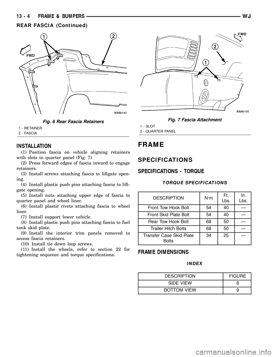
INSTALLATION
(1) Position fascia on vehicle aligning retainers
with slots in quarter panel (Fig. 7).
(2) Press forward edges of fascia inward to engage
retainers.
(3) Install screws attaching fascia to liftgate open-
ing.
(4) Install plastic push pins attaching fascia to lift-
gate opening.
(5) Install nuts attaching upper edge of fascia to
quarter panel and wheel liner.
(6) Install plastic rivets attaching fascia to wheel
liner.
(7) Install support lower vehicle.
(8) Install plastic push pins attaching fascia to fuel
tank skid plate.
(9) Install the interior trim panels removed to
access fascia retainers.
(10) Install tie down loop screws.
(11) Install the wheels, refer to section 22 for
tightening sequence and torque specifications.
FRAME
SPECIFICATIONS
SPECIFICATIONS - TORQUE
TORQUE SPECIFICATIONS
DESCRIPTION N´mFt.
Lbs.In.
Lbs.
Front Tow Hook Bolt 54 40 Ð
Front Skid Plate Bolt 54 40 Ð
Rear Tow Hook Bolt 68 50 Ð
Trailer Hitch Bolts 68 50 Ð
Transfer Case Skid Plate
Bolts34 25 Ð
FRAME DIMENSIONS
INDEX
DESCRIPTION FIGURE
SIDE VIEW 8
BOTTOM VIEW 9
Fig. 6 Rear Fascia Retainers
1 - RETAINER
2 - FASCIA
Fig. 7 Fascia Attachment
1 - SLOT
2 - QUARTER PANEL
13 - 4 FRAME & BUMPERSWJ
REAR FASCIA (Continued)
Page 1874 of 2199

BODY
TABLE OF CONTENTS
page page
BODY
DIAGNOSIS AND TESTING
WATER LEAKS........................1
WIND NOISE..........................2
STANDARD PROCEDURE
STANDARD PROCEDURE - BODY
LUBRICATION.........................2
STANDARD PROCEDURE - DRILLING AND
WELDING............................3
SPECIFICATIONS
BODY LUBRICANTS....................3
SPECIFICATIONS - TORQUE.............4
SPECIAL TOOLS
BODY...............................4DECKLID/HATCH/LIFTGATE/TAILGATE........5
DOOR - FRONT.........................11
DOORS - REAR.........................19
EXTERIOR.............................25
HOOD.................................33
INSTRUMENT PANEL SYSTEM.............36
INTERIOR..............................69
PAINT.................................81
SEATS................................83
STATIONARY GLASS.....................93
SUNROOF.............................96
WEATHERSTRIP/SEALS..................105
BODY STRUCTURE.....................112
BODY
DIAGNOSIS AND TESTING
WATER LEAKS
Water leaks can be caused by poor sealing,
improper body component alignment, body seam
porosity, missing plugs, or blocked drain holes. Cen-
trifugal and gravitational force can cause water to
drip from a location away from the actual leak point,
making leak detection difficult. All body sealing
points should be water tight in normal wet-driving
conditions. Water flowing downward from the front of
the vehicle should not enter the passenger or luggage
compartment. Moving sealing surfaces will not
always seal water tight under all conditions. At
times, side glass or door seals will allow water to
enter the passenger compartment during high pres-
sure washing or hard driving rain (severe) condi-
tions. Overcompensating on door or glass
adjustments to stop a water leak that occurs under
severe conditions can cause premature seal wear and
excessive closing or latching effort. After completing
a repair, water test vehicle to verify leak has stopped
before returning vehicle to use.
VISUAL INSPECTION BEFORE WATER LEAK TESTS
Verify that floor and body plugs are in place, body
drains are clear, and body components are properly
aligned and sealed. If component alignment or seal-
ing is necessary, refer to the appropriate section of
this group for proper procedures.
WATER LEAK TESTS
WARNING: DO NOT USE ELECTRIC SHOP LIGHTS
OR TOOLS IN WATER TEST AREA. PERSONAL
INJURY CAN RESULT.
When the conditions causing a water leak have
been determined, simulate the conditions as closely
as possible.
²If a leak occurs with the vehicle parked in a
steady light rain, flood the leak area with an open-
ended garden hose.
²If a leak occurs while driving at highway speeds
in a steady rain, test the leak area with a reasonable
velocity stream or fan spray of water. Direct the
spray in a direction comparable to actual conditions.
²If a leak occurs when the vehicle is parked on an
incline, hoist the end or side of the vehicle to simu-
late this condition. This method can be used when
the leak occurs when the vehicle accelerates, stops or
turns. If the leak occurs on acceleration, hoist the
front of the vehicle. If the leak occurs when braking,
hoist the back of the vehicle. If the leak occurs on left
turns, hoist the left side of the vehicle. If the leak
occurs on right turns, hoist the right side of the vehi-
cle. For hoisting recommendations refer to Group 0,
Lubrication and Maintenance, General Information
section.
WATER LEAK DETECTION
To detect a water leak point-of-entry, do a water
test and watch for water tracks or droplets forming
on the inside of the vehicle. If necessary, remove inte-
rior trim covers or panels to gain visual access to the
WJBODY 23 - 1
Page 1882 of 2199

LIFTGATE
REMOVAL
CAUTION: DO NOT DISCONNECT THE SUPPORT ROD
CYLINDERS WITH THE LIFTGATE CLOSED. THE SUP-
PORT ROD PISTONS ARE OPERATED BY HIGH PRES-
SURE GAS. THIS PRESSURE COULD CAUSE DAMAGE
AND /OR PERSONAL INJURY IF THEY ARE REMOVED
WHILE THE PISTONS ARE COMPRESSED.
(1) Open the liftgate. Support the liftgate for ease
of repair.
(2) Remove the liftgate trim panel.
(3) Remove the prop rods from the liftgate.
(4) Unplug the wire harnesses and disconnect the
washer hose.
(5) Mark the hinge location with a wax pencil or
other suitable device (Fig. 5).
(6) Remove the hinge screws and remove liftgate
from vehicle.
INSTALLATION
(1) Position the liftgate on the vehicle and align
the witness marks.
(2) Install the hinge screws at liftgate. Tighten
hinge screws to 28N´m (21ft. lbs.).
(3) Connect the wire harnesses and the washer
hose.
(4) Install the trim panel.
(5) Install the prop rods.
(6) Close the liftgate and check for proper latching
and alignment.
ADJUSTMENTS
LIFTGATE ADJUSTMENT
The position of the liftgate can be adjusted upward
or downward by the use of slots in the hinge. An
inward or outward adjustment is achieved by use of
slots in the body. If an inward or outward adjustment
is needed, use 3MŸ Fast and Firm or equivalent on
the hinge to body mating surface as a sealant.
TRIM PANEL
REMOVAL
REMOVAL - LIFTGATE TRIM PANEL
NOTE: The liftgate trim panel is attached with
screws and spring clips.
(1) Raise the liftgate.
(2) Remove the screws securing the liftgate trim
panel to the liftgate (Fig. 6).
(3) Disconnect the rear window defroster wires.
(4) Using a trim stick, or other suitable tool, pry
the liftgate trim panel off the liftgate.
Fig. 5 Liftgate
1 - HINGE
2 - LIFTGATE
Fig. 6 Liftgate Trim Panel
1 - LIFTGATE
2 - LIFTGATE TRIM PANEL
WJDECKLID/HATCH/LIFTGATE/TAILGATE 23 - 9
Page 1883 of 2199

REMOVAL - LOWER LIFTGATE OPENING TRIM
PANEL
(1) Remove screws at outboard end of lower lift-
gate trim panel.
(2) Open the spare tire cover and remove the
screws near the center of the lower liftgate trim
panel (Fig. 7).
(3) Remove the lower liftgate trim panel.
INSTALLATION
INSTALLATION - LIFTGATE TRIM PANEL
NOTE: The liftgate trim panel is attached with
screws and spring clips.
(1) Align the liftgate trim panel spring clips and
press the panel into the liftgate.
(2) Install the trim panel screws.
(3) Connect the rear defroster wires.
INSTALLATION - LOWER LIFTGATE OPENING
TRIM PANEL
(1) Align the screw holes and locators to the holes
in the liftgate opening.
(2) Install the screws in the liftgate opening trim
panel.
(3) Install the spare tire cover.
LIFTGATE INSULATOR
REMOVAL
(1) Remove the liftgate trim panel, refer to (Refer
to 23 - BODY/DECKLID/HATCH/LIFTGATE/TAIL-
GATE/TRIM PANEL - REMOVAL).
(2) Separate the liftgate insulator from the liftgate
and trim panel (Fig. 8).
INSTALLATION
(1) Thoroughly clean the area of any adhesive or
insulation material.
(2) Install the insulator in the liftgate.
(3) Install the liftgate trim panel refer to (Refer to
23 - BODY/DECKLID/HATCH/LIFTGATE/TAIL-
GATE/TRIM PANEL - INSTALLATION).
Fig. 7 Liftgate Opening Trim Panel
1 - UPPER LIFTGATE OPENING TRIM PANEL
2 - LOWER LIFTGATE OPENING TRIM PANEL
Fig. 8 Liftgate Insulator Pad
1 - LIFTGATE
2 - INSULATION PAD
23 - 10 DECKLID/HATCH/LIFTGATE/TAILGATEWJ
TRIM PANEL (Continued)
Page 1942 of 2199

INTERIOR
TABLE OF CONTENTS
page page
A-PILLAR TRIM
REMOVAL.............................69
INSTALLATION.........................69
ASSIST HANDLE
REMOVAL.............................70
INSTALLATION.........................70
B-PILLAR LOWER TRIM
REMOVAL.............................70
INSTALLATION.........................70
B-PILLAR UPPER TRIM
REMOVAL.............................71
INSTALLATION.........................71
CARPETS AND FLOOR MATS
REMOVAL
REMOVAL - FRONT CARPET............71
REMOVAL - CARGO AREA CARPET.......71
INSTALLATION
INSTALLATION - FRONT CARPET.........71
INSTALLATION - CARGO AREA CARPET . . . 72
COWL TRIM
REMOVAL.............................72
INSTALLATION.........................72
C-PILLAR TRIM
REMOVAL.............................72
INSTALLATION.........................72
DOOR SILL SCUFF PLATE
REMOVAL.............................74
INSTALLATION.........................74
DOOR SILL TRIM
REMOVAL.............................74INSTALLATION.........................74
D-PILLAR TRIM
REMOVAL.............................75
INSTALLATION.........................75
FLOOR CONSOLE
REMOVAL.............................76
INSTALLATION.........................76
HEADLINER
REMOVAL.............................77
INSTALLATION.........................77
LIFTGATE OPENING UPPER TRIM
REMOVAL.............................79
INSTALLATION.........................79
QUARTER TRIM PANEL
REMOVAL.............................79
INSTALLATION.........................79
REAR STORAGE BOX
REMOVAL.............................79
INSTALLATION.........................80
REAR VIEW MIRROR
REMOVAL.............................80
INSTALLATION
INSTALLATION.......................80
INSTALLATION - REARVIEW MIRROR
SUPPORT BRACKET...................80
SUN VISOR
REMOVAL.............................80
INSTALLATION.........................80
A-PILLAR TRIM
REMOVAL
The A-pillar trim is attached to the A-pillar with
spring clips.
(1) Grasp A-pillar trim and pull trim outward from
A-pillar (Fig. 1).
(2) Separate A-pillar trim from A-pillar.
INSTALLATION
(1) Position A-pillar trim on A-pillar and, starting
at the bottom, press into place (Fig. 1).
(2) Using a trim stick or other suitable tool, care-
fully cover the edge of the trim with weatherstrip.
Fig. 1 A-Pillar Trim
1 - A-PILLAR TRIM
2 - A-PILLAR
3 - SPRING CLIP
WJINTERIOR 23 - 69
Page 1950 of 2199

HEADLINER
REMOVAL
CAUTION: The headliner is a one-piece, molded
component. It has limited flexibility and must not be
bent. Damage may possibly result.
(1) Record radio presets and disconnect negative
battery cable.
(2) Remove A pillar trim moldings (Refer to 23 -
BODY/INTERIOR/A-PILLAR TRIM - REMOVAL).
(3) Remove B pillar upper trim moldings (Refer to
23 - BODY/INTERIOR/B-PILLAR UPPER TRIM -
REMOVAL).
(4) Remove C pillar trim moldings (Refer to 23 -
BODY/INTERIOR/C-PILLAR TRIM - REMOVAL).
(5) Remove D pillar trim molding (Refer to 23 -
BODY/INTERIOR/D-PILLAR TRIM - REMOVAL).
(6) Remove the sun visors (Refer to 23 - BODY/IN-
TERIOR/SUN VISOR - REMOVAL).
(7) Disconnect the vanity lamp electrical connector.
(8) Remove assist handles from roof rails (Refer to
23 - BODY/INTERIOR/ASSIST HANDLE - REMOV-
AL).
(9) Remove dome lamp and overhead console, if
equipped.
(10) Remove rear cargo/dome lamp.
(11) Remove sun roof pinch welt, if equipped.
(12) Disengage rear washer hose from liftgate (Fig.
9).
(13) Disengage the wire harness connectors at rear
of headliner.
(14) Disconnect the rear washer hose at the left
ªAº pillar (Fig. 10).
(15) Disengage the wire harness for the sunroof, if
equipped.
(16) Fold down the rear seats, move the front seats
full forward, and lower the front seat backs.
(17) Partially lower the headliner and disengage
the sunroof drain hoses, if equipped (Fig. 11).
(18) With the aid of an assistant, remove the head-
liner through the liftgate opening.
INSTALLATION
(1) With the aid of an assistant, position the head-
liner in the vehicle.
(2) Connect the sunroof drain hoses, if equipped.
(3) Connect the sunroof harness, the rear wire har-
nesses, and the washer hose at the ªAº pillar and at
the liftgate.
(4) Install the sunroof pinch welt, if equipped.
(5) Install the roof rail assist handles (Refer to 23 -
BODY/INTERIOR/ASSIST HANDLE - INSTALLA-
TION).
Fig. 9 Liftgate Washer Hose Routing at Rear of
Headliner
1 - ROOF
2 - REAR WASHER HOSE ROUTING
3 - REAR WASHER HOSE
4 - HEADLINER
Fig. 10 Rear Liftgate Washer Hose Routing at A
Pillar
1 - OVERHEAD CONSOLE WIRE HARNESS
2 - ROOF
3 - REAR WASHER HOSE
4 - REAR WASHER HOSE ROUTING
5 - HEADLINER
WJINTERIOR 23 - 77
Page 1952 of 2199

LIFTGATE OPENING UPPER
TRIM
REMOVAL
The upper liftgate opening trim is held on with
spring clips.
(1) Grasp the rear of the trim piece and pull down
and back to disengage clips (Fig. 12).
(2) Slide the trim piece to the rear to disengage
headliner locating hooks.
INSTALLATION
The liftgate upper opening trim piece is equipped
with headliner locating hooks (Fig. 13).
(1) Align the locating hooks with the slots in the
headliner.
(2) Engage the spring clips and press the liftgate
upper opening trim panel into place.
QUARTER TRIM PANEL
REMOVAL
(1) Move rear seat to cargo position.
(2) If equipped, remove sunshade cover.
(3) Open liftgate.
(4) Remove upper and lower liftgate opening trim
panels (Refer to 23 - BODY/INTERIOR/LIFTGATE
OPENING UPPER TRIM - REMOVAL).
(5) Remove D-pillar upper trim (Refer to 23 -
BODY/INTERIOR/D-PILLAR TRIM - REMOVAL).
(6) Remove storage bin (right side only) (Refer to
23 - BODY/INTERIOR/REAR STORAGE BOX -
REMOVAL).
(7) Remove C-pillar upper trim panel (Refer to 23 -
BODY/INTERIOR/C-PILLAR TRIM - REMOVAL).
(8) Remove mounting screws.
(9) Pull quarter trim panel forward and disengage
connectors for CD player and power outlet, if
equipped.
(10) Pull quarter trim panel extension in the rear
door opening upward.
(11) Remove rear quarter trim panel.
INSTALLATION
(1) Position quarter trim panel, engage connectors
for CD player and power outlet, if equipped, and
align screw holes.
(2) Install quarter trim panel.
(3) Install C-pillar upper trim panel (Refer to 23 -
BODY/INTERIOR/C-PILLAR TRIM - INSTALLA-
TION).
(4) Install storage bin (Refer to 23 - BODY/INTE-
RIOR/REAR STORAGE BOX - INSTALLATION).
(5) Install D-pillar upper trim panel (Refer to 23 -
BODY/INTERIOR/D-PILLAR TRIM - INSTALLA-
TION).
(6) Install upper and lower liftgate opening trim
panels (Refer to 23 - BODY/INTERIOR/LIFTGATE
OPENING UPPER TRIM - INSTALLATION).
(7) If equipped, install sunshade cover.
(8) Install cargo loops.
(9) Move the rear seat to the upright position.
REAR STORAGE BOX
REMOVAL
(1) Open the storage bin lid and remove screws on
each side of the lid hinge.
(2) Pull upward sharply on the bottom of the bin
to disengage hooks.
(3) Raise bin and move inboard to disengage the
quarter trim panel.
Fig. 12 Upper Liftgate Opening Trim
1 - UPPER LIFTGATE OPENING TRIM
Fig. 13 Headliner Locating Hooks
1 - UPPER LIFTGATE OPENING TRIM
2 - HEADLINER
WJINTERIOR 23 - 79