water pump JEEP GRAND CHEROKEE 2002 WJ / 2.G Repair Manual
[x] Cancel search | Manufacturer: JEEP, Model Year: 2002, Model line: GRAND CHEROKEE, Model: JEEP GRAND CHEROKEE 2002 WJ / 2.GPages: 2199, PDF Size: 76.01 MB
Page 1328 of 2199

(3) Turn engine off and let set for a few minutes
before restarting. Repeat this several times after
engine has reached normal operating temperature.
(4) Low oil pressure.
(5) The oil restrictor in cylinder head gasket or the
oil passage to the cylinder head is plugged with
debris.
(6) Air ingested into oil due to broken or cracked
oil pump pick up.
(7) Worn valve guides.
(8) Rocker arm ears contacting valve spring
retainer.
(9) Rocker arm loose, adjuster stuck or at maxi-
mum extension and still leaves lash in the system.
(10) Oil leak or excessive cam bore wear in cylin-
der head.
(11) Faulty lash adjuster.
a. Check lash adjusters for sponginess while
installed in cylinder head and cam on camshaft at
base circle. Depress part of rocker arm over adjuster.
Normal adjusters should feel very firm. Spongy
adjusters can be bottomed out easily.
b. Remove suspected lash adjusters, and replace.
c. Before installation, make sure adjusters are at
least partially full of oil. This can be verified by little
or no plunger travel when lash adjuster is depressed.
DIAGNOSIS AND TESTINGÐCYLINDER HEAD
GASKET
A cylinder head gasket leak can be located between
adjacent cylinders or between a cylinder and the
adjacent water jacket.
Possible indications of the cylinder head gasket
leaking between adjacent cylinders are:
²Loss of engine power
²Engine misfiring
²Poor fuel economy
Possible indications of the cylinder head gasket
leaking between a cylinder and an adjacent water
jacket are:
²Engine overheating
²Loss of coolant
²Excessive steam (white smoke) emitting from
exhaust
²Coolant foaming
CYLINDER-TO-CYLINDER LEAKAGE TEST
To determine if an engine cylinder head gasket is
leaking between adjacent cylinders, follow the proce-
dures in Cylinder Compression Pressure Test (Refer
to 9 - ENGINE - DIAGNOSIS AND TESTING). An
engine cylinder head gasket leaking between adja-
cent cylinders will result in approximately a 50±70%
reduction in compression pressure.
CYLINDER-TO-WATER JACKET LEAKAGE TEST
WARNING: USE EXTREME CAUTION WHEN THE
ENGINE IS OPERATING WITH COOLANT PRES-
SURE CAP REMOVED.
VISUAL TEST METHOD
With the engine cool, remove the coolant pressure
cap. Start the engine and allow it to warm up until
thermostat opens.
If a large combustion/compression pressure leak
exists, bubbles will be visible in the coolant.
COOLING SYSTEM TESTER METHOD
WARNING: WITH COOLING SYSTEM TESTER IN
PLACE, PRESSURE WILL BUILD UP FAST. EXCES-
SIVE PRESSURE BUILT UP, BY CONTINUOUS
ENGINE OPERATION, MUST BE RELEASED TO A
SAFE PRESSURE POINT. NEVER PERMIT PRES-
SURE TO EXCEED 138 kPa (20 psi).
Install Cooling System Tester 7700 or equivalent to
pressure cap neck. Start the engine and observe the
tester's pressure gauge. If gauge pulsates with every
power stroke of a cylinder a combustion pressure
leak is evident.
CHEMICAL TEST METHOD
Combustion leaks into the cooling system can also
be checked by using Bloc-Chek Kit C-3685-A or
equivalent. Perform test following the procedures
supplied with the tool kit.
REMOVAL
(1) Disconnect the negative cable from the battery.
(2) Raise the vehicle on a hoist.
(3) Disconnect the exhaust pipe at the left side
exhaust manifold.
(4) Drain the engine coolant. (Refer to 7 - COOL-
ING - STANDARD PROCEDURE).
(5) Lower the vehicle.
(6) Remove the intake manifold. (Refer to 9 -
ENGINE/MANIFOLDS/INTAKE MANIFOLD -
REMOVAL).
(7) Remove the cylinder head cover. (Refer to 9 -
ENGINE/CYLINDER HEAD/CYLINDER HEAD
COVER(S) - REMOVAL).
(8) Remove accessory drive belt. (Refer to 7 -
COOLING/ACCESSORY DRIVE/DRIVE BELTS -
REMOVAL).
(9) Remove the power steering pump and set
aside.
(10) Rotate the crankshaft until the damper tim-
ing mark is aligned with TDC indicator mark (Fig.
9).
WJENGINE - 4.7L 9 - 85
CYLINDER HEAD - LEFT (Continued)
Page 1379 of 2199

INTAKE MANIFOLD
DESCRIPTION
The intake manifold is made of a composite mate-
rial and features long runners which maximizes low
end torque. The intake manifold uses single plane
sealing which consist of eight individual press in
place port gaskets to prevent leaks. Eight studs and
two bolts are used to fasten the intake to the head.
DIAGNOSIS AND TESTINGÐINTAKE
MANIFOLD LEAKAGE
An intake manifold air leak is characterized by
lower than normal manifold vacuum. Also, one or
more cylinders may not be functioning.
WARNING: USE EXTREME CAUTION WHEN THE
ENGINE IS OPERATING. DO NOT STAND IN A
DIRECT LINE WITH THE FAN. DO NOT PUT YOUR
HANDS NEAR THE PULLEYS, BELTS OR THE FAN.
DO NOT WEAR LOOSE CLOTHING.
(1) Start the engine.
(2) Spray a small stream of water at the suspected
leak area.
(3) If a change in RPM is observed the area of the
suspected leak has been found.
(4) Repair as required.
REMOVAL
(1) Disconnect negative cable from battery.
(2) Remove air cleaner housing and throttle body
resonator (Fig. 104).
(3) Disconnect throttle and speed control cables.
(4) Disconnect electrical connectors for the follow-
ing components:
²Manifold Absolute Pressure (MAP) Sensor
²Intake Air Temperature (IAT) Sensor
²Throttle Position (TPS) Sensor
²Coolant Temperature (CTS) Sensor
²Idle Air Control (IAC) Motor
(5) Disconnect vapor purge hose, brake booster
hose, speed control servo hose, positive crankcase
ventilation (PCV) hose.
Fig. 102 Measuring Clearance Over Rotors
1 - STRAIGHT EDGE
2 - FEELER GAUGE
Fig. 103 Oil Pump and Primary Timing Chain
Tensioner Tightening Sequence
Fig. 104 Throttle Body Resonator
1 - THROTTLE BODY RESONATOR
2 - BOLT
3 - BOLT
9 - 136 ENGINE - 4.7LWJ
OIL PUMP (Continued)
Page 1433 of 2199

(2) Drain fuel tank and remove tank. Refer to Fuel
Tank Removal/Installation.
(3) Thoroughly wash and clean area around pump
module to prevent contaminants from entering tank.
(4) Disconnect fuel return and pressure lines from
fuel pump module fittings (Fig. 16). Refer to Quick-
Connect Fittings for procedures.
(5) The plastic fuel pump module locknut is
threaded onto fuel tank (Fig. 16). Install Special Tool
6856 to fuel pump module locknut and remove lock-
nut (Fig. 18). The fuel pump module will spring up
slightly after locknut is removed.
(6) Remove module from fuel tank.
INSTALLATION
Fuel tank removal will be necessary for fuel pump
module removal.
CAUTION: Whenever fuel pump module is serviced,
module gasket must be replaced.
(1) Thoroughly clean locknut threads and mating
fuel tank threads. Use a soap/water solution. Do not
use carburetor cleaner to clean threads.
(2) Using new gasket, position fuel pump module
into opening in fuel tank.
(3) Apply clean water to locknut threads.(4) Position locknut over top of fuel pump module.
(5) Rotate module until indexing arrow at top of
module (Fig. 19)is pointed toward rear of vehicle.
Align arrow to tick mark on top of fuel tank.This
step must be done to prevent float/float rod
assembly from contacting sides of fuel tank.
(6) Install Special Tool 6856 to locknut.
(7) Tighten locknut to 74 N´m (55 ft. lbs.) torque.
Fig. 17 FUEL PUMP MODULE
1 - FUEL PUMP MODULE
2 - FUEL GAUGE FLOAT
3 - ELECTRIC FUEL PUMP
4 - INLET FILTER
5 - FUEL GAUGE SENDING UNIT
6 - PIGTAIL HARNESS
Fig. 18 LOCKNUT REMOVAL/INSTALLATION -
TYPICAL
1 - SPECIAL TOOL 6856
2 - LOCKNUT
Fig. 19 FUEL PUMP MODULE INDEXING ARROW
1 - FUEL PUMP MODULE
2 - INDEXING ARROW
3 - FUEL SUPPLY (PRESSURE) FITTING
4 - FUEL RETURN FITTING
14 - 14 FUEL DELIVERYWJ
FUEL PUMP MODULE (Continued)
Page 1479 of 2199
DIAGNOSIS AND TESTING
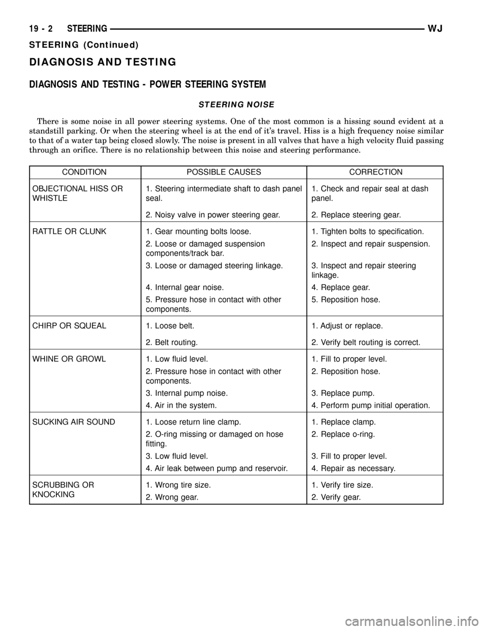
DIAGNOSIS AND TESTING - POWER STEERING SYSTEM
STEERING NOISE
There is some noise in all power steering systems. One of the most common is a hissing sound evident at a
standstill parking. Or when the steering wheel is at the end of it's travel. Hiss is a high frequency noise similar
to that of a water tap being closed slowly. The noise is present in all valves that have a high velocity fluid passing
through an orifice. There is no relationship between this noise and steering performance.
CONDITION POSSIBLE CAUSES CORRECTION
OBJECTIONAL HISS OR
WHISTLE1. Steering intermediate shaft to dash panel
seal.1. Check and repair seal at dash
panel.
2. Noisy valve in power steering gear. 2. Replace steering gear.
RATTLE OR CLUNK 1. Gear mounting bolts loose. 1. Tighten bolts to specification.
2. Loose or damaged suspension
components/track bar.2. Inspect and repair suspension.
3. Loose or damaged steering linkage. 3. Inspect and repair steering
linkage.
4. Internal gear noise. 4. Replace gear.
5. Pressure hose in contact with other
components.5. Reposition hose.
CHIRP OR SQUEAL 1. Loose belt. 1. Adjust or replace.
2. Belt routing. 2. Verify belt routing is correct.
WHINE OR GROWL 1. Low fluid level. 1. Fill to proper level.
2. Pressure hose in contact with other
components.2. Reposition hose.
3. Internal pump noise. 3. Replace pump.
4. Air in the system. 4. Perform pump initial operation.
SUCKING AIR SOUND 1. Loose return line clamp. 1. Replace clamp.
2. O-ring missing or damaged on hose
fitting.2. Replace o-ring.
3. Low fluid level. 3. Fill to proper level.
4. Air leak between pump and reservoir. 4. Repair as necessary.
SCRUBBING OR
KNOCKING1. Wrong tire size. 1. Verify tire size.
2. Wrong gear. 2. Verify gear.
19 - 2 STEERINGWJ
STEERING (Continued)
Page 1589 of 2199

(1) A result of restricted fluid flow through the
main and/or auxiliary cooler. This condition is usu-
ally the result of a faulty or improperly installed
drainback valve, a damaged main cooler, or severe
restrictions in the coolers and lines caused by debris
or kinked lines.
(2) Heavy duty operation with a vehicle not prop-
erly equipped for this type of operation. Trailer tow-
ing or similar high load operation will overheat the
transmission fluid if the vehicle is improperly
equipped. Such vehicles should have an auxiliary
transmission fluid cooler, a heavy duty cooling sys-
tem, and the engine/axle ratio combination needed to
handle heavy loads.
DIAGNOSIS AND TESTING - FLUID
CONTAMINATION
Transmission fluid contamination is generally a
result of:
²adding incorrect fluid
²failure to clean dipstick and fill tube when
checking level
²engine coolant entering the fluid
²internal failure that generates debris
²overheat that generates sludge (fluid break-
down)
²failure to reverse flush cooler and lines after
repair
²failure to replace contaminated converter after
repair
The use of non-recommended fluids can result in
transmission failure. The usual results are erratic
shifts, slippage, abnormal wear and eventual failure
due to fluid breakdown and sludge formation. Avoid
this condition by using recommended fluids only.
The dipstick cap and fill tube should be wiped
clean before checking fluid level. Dirt, grease and
other foreign material on the cap and tube could fall
into the tube if not removed beforehand. Take the
time to wipe the cap and tube clean before withdraw-
ing the dipstick.
Engine coolant in the transmission fluid is gener-
ally caused by a cooler malfunction. The only remedy
is to replace the radiator as the cooler in the radiator
is not a serviceable part. If coolant has circulated
through the transmission, an overhaul is necessary.
The transmission cooler and lines should be
reverse flushed whenever a malfunction generates
sludge and/or debris. The torque converter should
also be replaced at the same time.
Failure to flush the cooler and lines will result in
recontamination. Flushing applies to auxiliary coolers
as well. The torque converter should also be replaced
whenever a failure generates sludge and debris. This
is necessary because normal converter flushing proce-
dures will not remove all contaminants.
STANDARD PROCEDURE
STANDARD PROCEDURE - FLUID LEVEL
CHECK
Low fluid level can cause a variety of conditions
because it allows the pump to take in air along with
the fluid. As in any hydraulic system, air bubbles
make the fluid spongy, therefore, pressures will be
low and build up slowly.
Improper filling can also raise the fluid level too
high. When the transmssion has too much fluid, the
geartrain churns up foam and cause the same condi-
tions which occur with a low fluid level.
In either case, air bubbles can cause overheating
and/or fluid oxidation, and varnishing. This can
interfere with normal valve, clutch, and accumulator
operation. Foaming can also result in fluid escaping
from the transmission vent where it may be mis-
taken for a leak.
After the fluid has been checked, seat the dipstick
fully to seal out water and dirt.
The transmission has a dipstick to check oil level.
It is located on the right side of the engine. Be sure
to wipe all dirt from dipstick handle before removing.
Fluid level is checked with the engine running at
curb idle speed, the transmission in NEUTRAL and
the transmission fluid at normal operating tempera-
ture.The engine should be running at idle
speed for at least one minute, with the vehicle
on level ground.
The transmission fluid level can be checked two
ways.
PROCEDURE ONE
(1) Transmission fluid must be at normal operat-
ing temperature for accurate fluid level check. Drive
vehicle if necessary to bring fluid temperature up to
normal hot operating temperature of 82ÉC (180ÉF).
(2) Position vehicle on level surface.
(3) Start and run engine at curb idle speed.
(4) Apply parking brakes.
(5) Shift transmission momentarily into all gear
ranges. Then shift transmission back to NEUTRAL.
(6) Clean top of filler tube and dipstick to keep
dirt from entering tube.
(7) Remove dipstick (Fig. 87) and check fluid level
as follows:
(a) Correct acceptable level is in crosshatch area.
(b) Correct maximum level is to MAX arrow
mark.
(c) Incorrect level is at or below MIN line.
(d) If fluid is low, add only enough MopartAT F
+4, type 9602, to restore correct level. Do not over-
fill.
21 - 70 AUTOMATIC TRANSMISSION - 42REWJ
FLUID AND FILTER (Continued)
Page 1748 of 2199

STANDARD PROCEDURE
STANDARD PROCEDURE - FLUID LEVEL
CHECK
Low fluid level can cause a variety of conditions
because it allows the pump to take in air along with
the fluid. As in any hydraulic system, air bubbles
make the fluid spongy, therefore, pressures will be
low and build up slowly.
Improper filling can also raise the fluid level too
high. When the transmssion has too much fluid, the
geartrain churns up foam and cause the same condi-
tions which occur with a low fluid level.
In either case, air bubbles can cause overheating
and/or fluid oxidation, and varnishing. This can inter-
fere with normal valve, clutch, and accumulator opera-
tion. Foaming can also result in fluid escaping from the
transmission vent where it may be mistaken for a leak.
After the fluid has been checked, seat the dipstick
fully to seal out water and dirt.
The transmission has a dipstick to check oil level.
It is located on the right side of the engine. Be sure
to wipe all dirt from dipstick handle before removing.
The torque converter fills in both the P (PARK)
and N (NEUTRAL) positions. Place the selector lever
in P (PARK) to be sure that the fluid level check is
accurate.The engine should be running at idle
speed for at least one minute, with the vehicle
on level ground.At normal operating temperature(approximately 82 C. or 180 F.), the fluid level is cor-
rect if it is in the HOT region (cross-hatched area) on
the oil level indicator. The fluid level will be approx-
imately at the upper COLD hole of the dipstick at
70É F fluid temperature.
NOTE: Engine and Transmission should be at nor-
mal operating temperature before performing this
procedure.
(1) Start engine and apply parking brake.
(2) Shift the transmission into DRIVE for approxi-
mately 2 seconds.
(3) Shift the transmission into REVERSE for
approximately 2 seconds.
(4) Shift the transmission into PARK.
(5)
Hook up DRBtscan tool and select transmission.
(6) Select sensors.
(7) Read the transmission temperature value.
(8) Compare the fluid temperature value with the
chart. (Fig. 59)
(9) Adjust transmission fluid level shown on the
dipstick according to the chart.
NOTE: After adding any fluid to the transmission,
wait a minimum of 2 minutes for the oil to fully
drain from the fill tube into the transmission before
rechecking the fluid level.
(10) Check transmission for leaks.
Fig. 59 Transmission Fluid Temperature Chart
WJAUTOMATIC TRANSMISSION - 545RFE 21 - 229
FLUID AND FILTER (Continued)
Page 2087 of 2199

VACUUM RESERVOIR
DESCRIPTION.........................34
OPERATION...........................34
REMOVAL.............................35
INSTALLATION.........................35EVAPORATOR TEMPERATURE SENSOR
DESCRIPTION.........................35
OPERATION...........................35
REMOVAL.............................35
INSTALLATION.........................35
CONTROLS
DIAGNOSIS AND TESTING - VACUUM SYSTEM
Vacuum control is used to operate the mode doors
in the standard equipment manual temperature con-
trol system HVAC housing. Testing of the A/C Heater
mode control switch operation will determine if the
vacuum and electrical controls are functioning. How-
ever, it is possible that a vacuum control system that
operates perfectly at engine idle (high engine vac-
uum) may not function properly at high engine
speeds or loads (low engine vacuum). This can be
caused by leaks in the vacuum system, or a faulty
vacuum check valve.
A vacuum system test will help to identify the
source of poor vacuum system performance or vac-
uum system leaks. Before starting this test, stop the
engine and make certain that the problem isn't a dis-
connected vacuum supply tube at the engine intake
manifold vacuum tap or the vacuum reservoir.
Use an adjustable vacuum test set (Special Tool
C-3707-B) and a suitable vacuum pump to test the
HVAC vacuum control system. With a finger placed
over the end of the vacuum test hose probe (Fig. 1),
adjust the bleed valve on the test set gauge to obtain
a vacuum of exactly 27 kPa (8 in. Hg.). Release and
block the end of the probe several times to verify that
the vacuum reading returns to the exact 27 kPa (8
in. Hg.) setting. Otherwise, a false reading will be
obtained during testing.
VACUUM CHECK VALVES
(1) Remove the vacuum check valve to be tested.
The valves are located in the (black) vacuum supply
tubes at either the engine intake manifold vacuum
tap, or on the bottom of the HVAC unit behind the
passenger front floor duct.
(2) Connect the test set vacuum supply hose to the
A/C Heater control side of the valve. When connected
to this side of the check valve, no vacuum should
pass and the test set gauge should return to the 27
kPa (8 in. Hg.) setting. If OK, go to Step 3. If not OK,
replace the faulty valve.
(3) Connect the test set vacuum supply hose to the
engine vacuum side of the valve. When connected to
this side of the check valve, vacuum should flow
through the valve without restriction. If not OK,
replace the faulty valve.
A/C HEATER CONTROL
(1) Connect the test set vacuum probe to the
HVAC vacuum supply (black) tube in the engine com-
partment. Position the test set gauge so that it can
be viewed from the passenger compartment.
(2) Place the A/C Heater mode control switch knob
in each mode position, one position at a time, and
pause after each selection. The test set gauge should
return to the 27 kPa (8 in. Hg.) setting shortly after
each selection is made. If not OK, a component or
vacuum line in the vacuum circuit of the selected
mode has a leak. See the procedure in Locating Vac-
uum Leaks.
CAUTION: Do not use lubricant on the switch ports
or in the holes in the plug, as lubricant will ruin the
vacuum valve in the switch. A drop of clean water
in the connector plug holes will help the connector
slide onto the switch ports.
Fig. 1 ADJUST VACUUM TEST BLEED VALVE -
TYPICAL
1 - VACUUM PUMP TOOL C-4289
2 - VACUUM TEST SET C-3707
3 - BLEED VALVE
4 - PROBE
24 - 10 CONTROLSWJ
Page 2160 of 2199
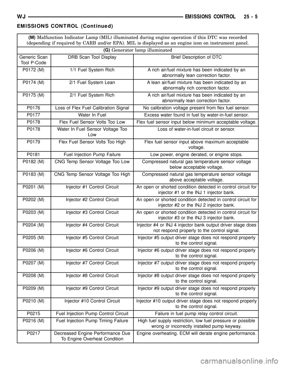
(M)Malfunction Indicator Lamp (MIL) illuminated during engine operation if this DTC was recorded
(depending if required by CARB and/or EPA). MIL is displayed as an engine icon on instrument panel.
(G)Generator lamp illuminated
Generic Scan
Tool P-CodeDRB Scan Tool Display Brief Description of DTC
P0172 (M) 1/1 Fuel System Rich A rich air/fuel mixture has been indicated by an
abnormally lean correction factor.
P0174 (M) 2/1 Fuel System Lean A lean air/fuel mixture has been indicated by an
abnormally rich correction factor.
P0175 (M) 2/1 Fuel System Rich A rich air/fuel mixture has been indicated by an
abnormally lean correction factor.
P0176 Loss of Flex Fuel Calibration Signal No calibration voltage present from flex fuel sensor.
P0177 Water In Fuel Excess water found in fuel by water-in-fuel sensor.
P0178 Flex Fuel Sensor Volts Too Low Flex fuel sensor input below minimum acceptable voltage.
P0178 Water In Fuel Sensor Voltage Too
LowLoss of water-in-fuel circuit or sensor.
P0179 Flex Fuel Sensor Volts Too High Flex fuel sensor input above maximum acceptable
voltage.
P0181 Fuel Injection Pump Failure Low power, engine derated, or engine stops.
P0182 (M) CNG Temp Sensor Voltage Too Low Compressed natural gas temperature sensor voltage
below acceptable voltage.
P0183 (M) CNG Temp Sensor Voltage Too High Compressed natural gas temperature sensor voltage
above acceptable voltage.
P0201 (M) Injector #1 Control Circuit An open or shorted condition detected in control circuit for
injector #1 or the INJ 1 injector bank.
P0202 (M) Injector #2 Control Circuit An open or shorted condition detected in control circuit for
injector #2 or the INJ 2 injector bank.
P0203 (M) Injector #3 Control Circuit An open or shorted condition detected in control circuit for
injector #3 or the INJ 3 injector bank.
P0204 (M) Injector #4 Control Circuit Injector #4 or INJ 4 injector bank output driver stage does
not respond properly to the control signal.
P0205 (M) Injector #5 Control Circuit Injector #5 output driver stage does not respond properly
to the control signal.
P0206 (M) Injector #6 Control Circuit Injector #6 output driver stage does not respond properly
to the control signal.
P0207 (M) Injector #7 Control Circuit Injector #7 output driver stage does not respond properly
to the control signal.
P0208 (M) Injector #8 Control Circuit Injector #8 output driver stage does not respond properly
to the control signal.
P0209 (M) Injector #9 Control Circuit Injector #9 output driver stage does not respond properly
to the control signal.
P0210 (M) Injector #10 Control Circuit Injector #10 output driver stage does not respond properly
to the control signal.
P0215 Fuel Injection Pump Control Circuit Failure in fuel pump relay control circuit.
P0216 (M) Fuel Injection Pump Timing Failure High fuel supply restriction, low fuel pressure or possible
wrong or incorrectly installed pump keyway.
P0217 Decreased Engine Performance Due
To Engine Overheat ConditionEngine overheating. ECM will derate engine performance.
WJEMISSIONS CONTROL 25 - 5
EMISSIONS CONTROL (Continued)
Page 2173 of 2199

tive system and seal the evaporative system so the
leak detection test can be run.
The primary components within the assembly are:
A three port solenoid that activates both of the func-
tions listed above; a pump which contains a switch,
two check valves and a spring/diaphragm, a canister
vent valve (CVV) seal which contains a spring loaded
vent seal valve.
Immediately after a cold start, between predeter-
mined temperature thresholds limits, the three port
solenoid is briefly energized. This initializes the
pump by drawing air into the pump cavity and also
closes the vent seal. During non test conditions the
vent seal is held open by the pump diaphragm
assembly which pushes it open at the full travel posi-
tion. The vent seal will remain closed while the
pump is cycling due to the reed switch triggering of
the three port solenoid that prevents the diaphragm
assembly from reaching full travel. After the brief
initialization period, the solenoid is de-energized
allowing atmospheric pressure to enter the pump
cavity, thus permitting the spring to drive the dia-
phragm which forces air out of the pump cavity and
into the vent system. When the solenoid is energized
and de energized, the cycle is repeated creating flow
in typical diaphragm pump fashion. The pump is con-
trolled in 2 modes:
Pump Mode:The pump is cycled at a fixed rate to
achieve a rapid pressure build in order to shorten the
overall test length.
Test Mode:The solenoid is energized with a fixed
duration pulse. Subsequent fixed pulses occur when
the diaphragm reaches the Switch closure point.
The spring in the pump is set so that the system
will achieve an equalized pressure of about 7.5º
water. The cycle rate of pump strokes is quite rapid
as the system begins to pump up to this pressure. As
the pressure increases, the cycle rate starts to drop
off. If there is no leak in the system, the pump would
eventually stop pumping at the equalized pressure. If
there is a leak, it will continue to pump at a rate rep-
resentative of the flow characteristic of the size of the
leak. From this information we can determine if the
leak is larger than the required detection limit (cur-
rently set at .040º orifice by CARB). If a leak is
revealed during the leak test portion of the test, the
test is terminated at the end of the test mode and no
further system checks will be performed.
After passing the leak detection phase of the test,
system pressure is maintained by turning on the
LDP's solenoid until the purge system is activated.
Purge activation in effect creates a leak. The cycle
rate is again interrogated and when it increases due
to the flow through the purge system, the leak check
portion of the diagnostic is complete.The canister vent valve will unseal the system
after completion of the test sequence as the pump
diaphragm assembly moves to the full travel position.
Evaporative system functionality will be verified by
using the stricter evap purge flow monitor. At an
appropriate warm idle the LDP will be energized to
seal the canister vent. The purge flow will be clocked
up from some small value in an attempt to see a
shift in the 02 control system. If fuel vapor, indicated
by a shift in the 02 control, is present the test is
passed. If not, it is assumed that the purge system is
not functioning in some respect. The LDP is again
turned off and the test is ended.
MISFIRE MONITOR
Excessive engine misfire results in increased cata-
lyst temperature and causes an increase in HC emis-
sions. Severe misfires could cause catalyst damage.
To prevent catalytic convertor damage, the PCM
monitors engine misfire.
The Powertrain Control Module (PCM) monitors
for misfire during most engine operating conditions
(positive torque) by looking at changes in the crank-
shaft speed. If a misfire occurs the speed of the
crankshaft will vary more than normal.
FUEL SYSTEM MONITOR
To comply with clean air regulations, vehicles are
equipped with catalytic converters. These converters
reduce the emission of hydrocarbons, oxides of nitro-
gen and carbon monoxide. The catalyst works best
when the Air Fuel (A/F) ratio is at or near the opti-
mum of 14.7 to 1.
The PCM is programmed to maintain the optimum
air/fuel ratio of 14.7 to 1. This is done by making
short term corrections in the fuel injector pulse width
based on the O2S sensor output. The programmed
memory acts as a self calibration tool that the engine
controller uses to compensate for variations in engine
specifications, sensor tolerances and engine fatigue
over the life span of the engine. By monitoring the
actual fuel-air ratio with the O2S sensor (short term)
and multiplying that with the program long-term
(adaptive) memory and comparing that to the limit,
it can be determined whether it will pass an emis-
sions test. If a malfunction occurs such that the PCM
cannot maintain the optimum A/F ratio, then the
MIL will be illuminated.
CATALYST MONITOR
To comply with clean air regulations, vehicles are
equipped with catalytic converters. These converters
reduce the emission of hydrocarbons, oxides of nitro-
gen and carbon monoxide.
Normal vehicle miles or engine misfire can cause a
catalyst to decay. This can increase vehicle emissions
25 - 18 EMISSIONS CONTROLWJ
EMISSIONS CONTROL (Continued)