water pump JEEP GRAND CHEROKEE 2002 WJ / 2.G User Guide
[x] Cancel search | Manufacturer: JEEP, Model Year: 2002, Model line: GRAND CHEROKEE, Model: JEEP GRAND CHEROKEE 2002 WJ / 2.GPages: 2199, PDF Size: 76.01 MB
Page 236 of 2199

STANDARD PROCEDURE - DRAINING COOLING
SYSTEM - 4.0L ENGINE
WARNING: DO NOT REMOVE THE CYLINDER
BLOCK DRAIN PLUGS OR LOOSEN THE RADIATOR
DRAINCOCK WITH SYSTEM HOT AND UNDER
PRESSURE. SERIOUS BURNS FROM COOLANT
CAN OCCUR.
(1) DO NOT remove radiator cap first. With engine
cold, raise vehicle on a hoist and locate radiator
draincock.
NOTE: Radiator draincock is located on the right/
lower side of radiator facing to rear of vehicle.
(2) Attach one end of a hose to the draincock. Put
the other end into a clean container. Open draincock
and drain coolant from radiator. This will empty the
coolant reserve/overflow tank. The coolant does not
have to be removed from the tank unless the system
is being refilled with a fresh mixture. When tank is
empty, remove radiator cap and continue draining
cooling system.
To drain the engine of coolant, remove the cylinder
block drain plug located on the side of cylinder block
(Fig. 9).
STANDARD PROCEDURE - REFILLING
COOLING SYSTEM - 4.0L ENGINE
(1) Tighten the radiator draincock and the cylinder
block drain plug(s) (if removed).
(2) Fill system using a 50/50 mixture of ethylene-
glycol antifreeze and low mineral content water. Fill
radiator to top and install radiator cap. Add suffi-
cient coolant to the reserve/overflow tank to raise
level to FULL mark.
(3) With heater control unit in the HEAT position,
operate engine with radiator cap in place.
(4) After engine has reached normal operating
temperature, shut engine off and allow it to cool.
When engine is cooling down, coolant will be drawn
into the radiator from the reserve/overflow tank.
(5) Add coolant to reserve/overflow tank as neces-
sary.Only add coolant to the reserve/overflow
tank when the engine is cold. Coolant level in a
warm engine will be higher due to thermal
expansion.To purge the cooling system of all air,
this heat up/cool down cycle (adding coolant to cold
engine) must be performed three times. Add neces-
sary coolant to raise tank level to the FULL mark
after each cool down period.
STANDARD PROCEDURE - ADDING
ADDITIONAL COOLANT
The use of aluminum cylinder blocks, cylinder
heads and water pumps requires special corrosion
protection. Only MopartAntifreeze/Coolant, 5
Year/100,000 Mile Formula (glycol base coolant with
Fig. 8 Cooling System Bleed Plug - 4.7L
1 - COOLING SYSTEM BLEED PLUG
Fig. 9 Drain PlugÐ4.0L Engine
1 - COOLANT TEMPERATURE SENSOR
2 - BLOCK DRAIN PLUG
WJCOOLING 7 - 13
COOLING (Continued)
Page 237 of 2199

corrosion inhibitors called HOAT, for Hybrid Organic
Additive Technology) is recommended. This coolant
offers the best engine cooling without corrosion when
mixed with 50% distilled water to obtain to obtain a
freeze point of -37ÉC (-35ÉF). If it loses color or
becomes contaminated, drain, flush, and replace with
fresh properly mixed coolant solution.
CAUTION: Do not use coolant additives that are
claimed to improve engine cooling.
STANDARD PROCEDURE - COOLING SYSTEM -
REVERSE FLUSHING
CAUTION: The cooling system normally operates at
97-to-124 kPa (14-to -18 psi) pressure. Exceeding
this pressure may damage the radiator or hoses.
Reverse flushing of the cooling system is the forc-
ing of water through the cooling system. This is done
using air pressure in the opposite direction of normal
coolant flow. It is usually only necessary with very
dirty systems with evidence of partial plugging.
CHEMICAL CLEANING
If visual inspection indicates the formation of
sludge or scaly deposits, use a radiator cleaner
(Mopar Radiator Kleen or equivalent) before flushing.
This will soften scale and other deposits and aid the
flushing operation.
CAUTION: Be sure instructions on the container are
followed.
REVERSE FLUSHING RADIATOR
Disconnect the radiator hoses from the radiator fit-
tings. Attach a section of radiator hose to the radia-
tor bottom outlet fitting and insert the flushing gun.
Connect a water supply hose and air supply hose to
the flushing gun.
CAUTION: The cooling system normally operates at
97-to-124 kPa (14- to-18 psi) pressure. Exceeding
this pressure may damage the radiator or hoses.
Allow the radiator to fill with water. When radiator
is filled, apply air in short blasts allowing radiator to
refill between blasts. Continue this reverse flushing
until clean water flows out through rear of radiator
cooling tube passages. For more information, refer to
operating instructions supplied with flushing equip-
ment. Have radiator cleaned more extensively by a
radiator repair shop.
REVERSE FLUSHING ENGINE
Drain the cooling system (Refer to 7 - COOLING -
STANDARD PROCEDURE). Remove the thermostat
housing and thermostat. Install the thermostat hous-
ing. Disconnect the radiator upper hose from the
radiator and attach the flushing gun to the hose. Dis-
connect the radiator lower hose from the water
pump. Attach a lead away hose to the water pump
inlet fitting.
CAUTION: Be sure that the heater control valve is
closed (heat off). This is done to prevent coolant
flow with scale and other deposits from entering
the heater core.
Connect the water supply hose and air supply hose
to the flushing gun. Allow the engine to fill with
water. When the engine is filled, apply air in short
blasts, allowing the system to fill between air blasts.
Continue until clean water flows through the lead
away hose. For more information, refer to operating
instructions supplied with flushing equipment.
Remove the lead away hose, flushing gun, water
supply hose and air supply hose. Remove the thermo-
stat housing (Refer to 7 - COOLING/ENGINE/EN-
GINE COOLANT THERMOSTAT - REMOVAL).
Install the thermostat and housing with a replace-
ment gasket (Refer to 7 - COOLING/ENGINE/EN-
GINE COOLANT THERMOSTAT -
INSTALLATION). Connect the radiator hoses. Refill
the cooling system with the correct antifreeze/water
mixture (Refer to 7 - COOLING - STANDARD PRO-
CEDURE).
SPECIFICATIONS
TORQUE
DESCRIPTION N´m Ft. In.
Lbs. Lbs.
Automatic Belt Tensioner to
Mounting
BracketÐBolt
4.0L 28 Ð 250
4.7L 41 30 Ð
Automatic Belt Tensioner
PulleyÐ
Bolt
(4.7L) 61 45 Ð
Block HeaterÐBolt
7 - 14 COOLINGWJ
COOLING (Continued)
Page 238 of 2199
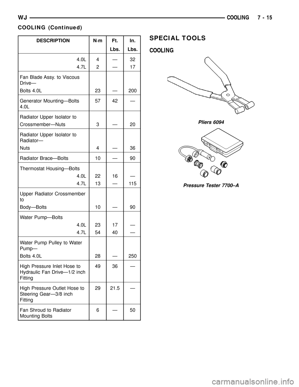
DESCRIPTION N´m Ft. In.
Lbs. Lbs.
4.0L 4 Ð 32
4.7L 2 Ð 17
Fan Blade Assy. to Viscous
DriveÐ
Bolts 4.0L 23 Ð 200
Generator MountingÐBolts
4.0L57 42 Ð
Radiator Upper Isolator to
CrossmemberÐNuts 3 Ð 20
Radiator Upper Isolator to
RadiatorÐ
Nuts 4 Ð 36
Radiator BraceÐBolts 10 Ð 90
Thermostat HousingÐBolts
4.0L 22 16 Ð
4.7L 13 Ð 115
Upper Radiator Crossmember
to
BodyÐBolts 10 Ð 90
Water PumpÐBolts
4.0L 23 17 Ð
4.7L 54 40 Ð
Water Pump Pulley to Water
PumpÐ
Bolts 4.0L 28 Ð 250
High Pressure Inlet Hose to
Hydraulic Fan DriveÐ1/2 inch
Fitting49 36 Ð
High Pressure Outlet Hose to
Steering GearÐ3/8 inch
Fitting29 21.5 Ð
Fan Shroud to Radiator
Mounting Bolts6Ð50SPECIAL TOOLS
COOLING
Pliers 6094
Pressure Tester 7700±A
WJCOOLING 7 - 15
COOLING (Continued)
Page 242 of 2199
CONDITION POSSIBLE CAUSES CORRECTION
BELT BROKEN (NOTE: IDENTIFY
AND CORRECT PROBLEM
BEFORE NEW BELT IS
INSTALLED)1. Excessive tension. 1. Replace belt and automatic belt
tensioner.
2. Incorrect belt. 2. Replace belt.
3. Tensile member damaged during
belt installation.3. Replace belt.
4. Severe misalignment. 4. Check and replace.
5. Bracket, pulley, or bearing failure. 5. Replace defective component
and belt.
NOISE (OBJECTIONABLE
SQUEAL, SQUEAK, OR RUMBLE
IS HEARD OR FELT WHILE
DRIVE BELT IS IN OPERATION)1. Belt slippage. 1. Replace belt or automatic belt
tensioner.
2. Bearing noise. 2. Locate and repair.
3. Belt misalignment. 3. Replace belt.
4. Belt-to-pulley mismatch. 4. Install correct belt.
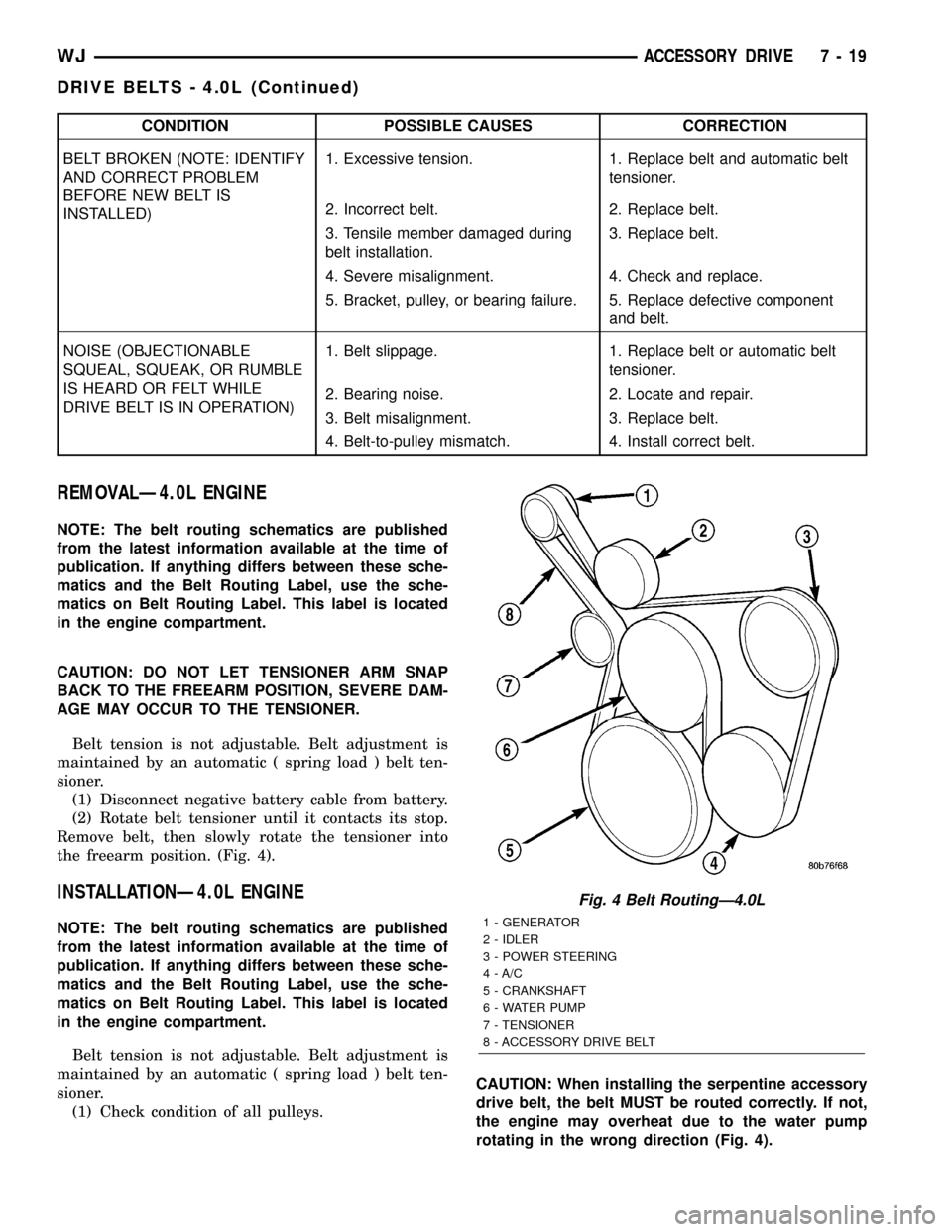
REMOVALÐ4.0L ENGINE
NOTE: The belt routing schematics are published
from the latest information available at the time of
publication. If anything differs between these sche-
matics and the Belt Routing Label, use the sche-
matics on Belt Routing Label. This label is located
in the engine compartment.
CAUTION: DO NOT LET TENSIONER ARM SNAP
BACK TO THE FREEARM POSITION, SEVERE DAM-
AGE MAY OCCUR TO THE TENSIONER.
Belt tension is not adjustable. Belt adjustment is
maintained by an automatic ( spring load ) belt ten-
sioner.
(1) Disconnect negative battery cable from battery.
(2) Rotate belt tensioner until it contacts its stop.
Remove belt, then slowly rotate the tensioner into
the freearm position. (Fig. 4).
INSTALLATIONÐ4.0L ENGINE
NOTE: The belt routing schematics are published
from the latest information available at the time of
publication. If anything differs between these sche-
matics and the Belt Routing Label, use the sche-
matics on Belt Routing Label. This label is located
in the engine compartment.
Belt tension is not adjustable. Belt adjustment is
maintained by an automatic ( spring load ) belt ten-
sioner.
(1) Check condition of all pulleys.CAUTION: When installing the serpentine accessory
drive belt, the belt MUST be routed correctly. If not,
the engine may overheat due to the water pump
rotating in the wrong direction (Fig. 4).
Fig. 4 Belt RoutingÐ4.0L
1 - GENERATOR
2 - IDLER
3 - POWER STEERING
4 - A/C
5 - CRANKSHAFT
6 - WATER PUMP
7 - TENSIONER
8 - ACCESSORY DRIVE BELT
WJACCESSORY DRIVE 7 - 19
DRIVE BELTS - 4.0L (Continued)
Page 245 of 2199
CONDITION POSSIBLE CAUSES CORRECTION
BELT BROKEN (NOTE: IDENTIFY
AND CORRECT PROBLEM
BEFORE NEW BELT IS
INSTALLED)1. Excessive tension. 1. Replace belt and automatic belt
tensioner.
2. Incorrect belt. 2. Replace belt.
3. Tensile member damaged during
belt installation.3. Replace belt.
4. Severe misalignment. 4. Check and replace.
5. Bracket, pulley, or bearing failure. 5. Replace defective component
and belt.
NOISE (OBJECTIONABLE
SQUEAL, SQUEAK, OR RUMBLE
IS HEARD OR FELT WHILE
DRIVE BELT IS IN OPERATION)1. Belt slippage. 1. Replace belt or automatic belt
tensioner.
2. Bearing noise. 2. Locate and repair.
3. Belt misalignment. 3. Replace belt.
4. Belt-to-pulley mismatch. 4. Install correct belt.
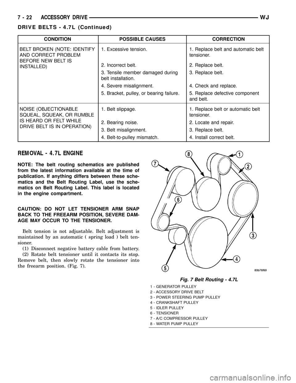
REMOVAL - 4.7L ENGINE
NOTE: The belt routing schematics are published
from the latest information available at the time of
publication. If anything differs between these sche-
matics and the Belt Routing Label, use the sche-
matics on Belt Routing Label. This label is located
in the engine compartment.
CAUTION: DO NOT LET TENSIONER ARM SNAP
BACK TO THE FREEARM POSITION, SEVERE DAM-
AGE MAY OCCUR TO THE TENSIONER.
Belt tension is not adjustable. Belt adjustment is
maintained by an automatic ( spring load ) belt ten-
sioner.
(1) Disconnect negative battery cable from battery.
(2) Rotate belt tensioner until it contacts its stop.
Remove belt, then slowly rotate the tensioner into
the freearm position. (Fig. 7).
Fig. 7 Belt Routing - 4.7L
1 - GENERATOR PULLEY
2 - ACCESSORY DRIVE BELT
3 - POWER STEERING PUMP PULLEY
4 - CRANKSHAFT PULLEY
5 - IDLER PULLEY
6 - TENSIONER
7 - A/C COMPRESSOR PULLEY
8 - WATER PUMP PULLEY
7 - 22 ACCESSORY DRIVEWJ
DRIVE BELTS - 4.7L (Continued)
Page 246 of 2199

INSTALLATION - 4.7L ENGINE
NOTE: The belt routing schematics are published
from the latest information available at the time of
publication. If anything differs between these sche-
matics and the Belt Routing Label, use the sche-
matics on Belt Routing Label. This label is located
in the engine compartment.
Belt tension is not adjustable. Belt adjustment is
maintained by an automatic ( spring load ) belt ten-
sioner.
(1) Check condition of all pulleys.
CAUTION: When installing the serpentine accessory
drive belt, the belt MUST be routed correctly. If not,
the engine may overheat due to the water pump
rotating in the wrong direction (Fig. 7).
(2) Install new belt (Fig. 7). Route the belt around
all pulleys except the idler pulley. Rotate the ten-
sioner arm until it contacts its stop position. Route
the belt around the idler and slowly let the tensioner
rotate into the belt. Make sure the belt is seated onto
all pulleys.(3) With the drive belt installed, inspect the belt
wear indicator (Fig. 8). On 4.7L Engines the gap
between the tang and the housing stop ( measure-
ment A ) must not exceed 24 mm (.94 inches).
Fig. 8 Accessory Drive Belt Wear Indicator
1 - AUTOMATIC TENSIONER ASSEMBLY
WJACCESSORY DRIVE 7 - 23
DRIVE BELTS - 4.7L (Continued)
Page 247 of 2199

ENGINE
TABLE OF CONTENTS
page page
COOLANT
DESCRIPTION
DESCRIPTION - ENGINE COOLANT.......25
DESCRIPTION - HOAT COOLANT.........25
OPERATION...........................26
COOLANT LEVEL SENSOR
REMOVAL.............................26
INSTALLATION.........................26
COOLANT RECOVERY PRESS CONTAINER
DESCRIPTION.........................27
RADIATOR FAN - 4.7L
DESCRIPTION.........................27
OPERATION...........................28
REMOVAL.............................29
CLEANING............................30
INSTALLATION.........................30
RADIATOR FAN - 4.0L
DESCRIPTION.........................31
REMOVAL.............................31
CLEANING............................32
INSPECTION..........................32
INSTALLATION.........................32
ENGINE BLOCK HEATER
DESCRIPTION
DESCRIPTIONÐ4.7L ENGINE............32
DESCRIPTIONÐ4.0L ENGINE............32
OPERATION...........................33
DIAGNOSIS AND TESTINGÐENGINE BLOCK
HEATER ............................33
REMOVAL
REMOVALÐ4.7L ENGINE...............33
REMOVALÐ4.0L ENGINE...............34
INSTALLATION
INSTALLATIONÐ4.7L ENGINE...........34
INSTALLATIONÐ4.0L ENGINE...........34
ENGINE COOLANT TEMP SENSOR
DESCRIPTION.........................35
OPERATION...........................35
REMOVAL
REMOVALÐ4.0L ENGINE...............35
REMOVALÐ4.7L ENGINE...............36
INSTALLATION
INSTALLATIONÐ4.0L ENGINE...........36
INSTALLATIONÐ4.7L ENGINE...........36
ENGINE COOLANT THERMOSTAT
DESCRIPTION
DESCRIPTIONÐ4.7L ENGINE............36
DESCRIPTIONÐ4.0L ENGINE............37
OPERATION...........................37DIAGNOSIS AND TESTINGÐTHERMOSTAT . . . 37
REMOVAL
REMOVALÐ4.0L ENGINE...............38
REMOVALÐ4.7L ENGINE...............38
INSTALLATION
INSTALLATIONÐ4.0L ENGINE...........38
INSTALLATIONÐ4.7L ENGINE...........39
FAN DRIVE VISCOUS CLUTCH - 4.0L
DESCRIPTION.........................40
OPERATION...........................40
DIAGNOSIS AND TESTINGÐVISCOUS FAN
DRIVE..............................40
PWM FAN CONTROL MODULE - 4.0L
DESCRIPTION.........................41
OPERATION...........................41
REMOVAL.............................41
INSTALLATION.........................42
RADIATOR - 4.7L
DESCRIPTION.........................42
REMOVAL.............................42
CLEANING............................43
INSPECTION..........................44
INSTALLATION.........................44
RADIATOR - 4.0L
DESCRIPTION.........................44
REMOVAL.............................44
CLEANING............................46
INSPECTION..........................47
INSTALLATION.........................47
RADIATOR FAN MOTOR
DIAGNOSIS AND TESTINGÐELECTRIC
COOLING FAN........................47
WATER PUMP - 4.7L
DESCRIPTION
DESCRIPTIONÐWATER PUMP...........47
DESCRIPTIONÐWATER PUMP BYPASS....47
OPERATION
OPERATIONÐWATER PUMP............47
OPERATIONÐWATER PUMP BYPASS.....48
DIAGNOSIS AND TESTINGÐWATER PUMP . . . 48
REMOVAL.............................49
CLEANING............................49
INSPECTION..........................49
INSTALLATION.........................49
WATER PUMP - 4.0L
DESCRIPTION.........................50
DIAGNOSIS AND TESTINGÐWATER PUMP . . . 50
REMOVAL.............................51
CLEANING............................52
7 - 24 ENGINEWJ
Page 248 of 2199

INSPECTION..........................52
INSTALLATION.........................52
RADIATOR PRESSURE CAP
DESCRIPTION.........................53
OPERATION...........................53
DIAGNOSIS AND TESTINGÐRADIATOR
PRESSURE CAP......................53CLEANING............................53
INSPECTION..........................54
WATER PUMP INLET TUBE
REMOVAL.............................54
INSTALLATION.........................54
COOLANT
DESCRIPTION
DESCRIPTION - ENGINE COOLANT
ETHYLENE-GLYCOL MIXTURES
CAUTION: Richer antifreeze mixtures cannot be
measured with normal field equipment and can
cause problems associated with 100 percent ethyl-
ene-glycol.
The required ethylene-glycol (antifreeze) and water
mixture depends upon the climate and vehicle oper-
ating conditions. The recommended mixture of 50/50
ethylene-glycol and water will provide protection
against freezing to -37 deg. C (-35 deg. F). The anti-
freeze concentrationmust alwaysbe a minimum of
44 percent, year-round in all climates.If percentage
is lower than 44 percent, engine parts may be
eroded by cavitation, and cooling system com-
ponents may be severely damaged by corrosion.
Maximum protection against freezing is provided
with a 68 percent antifreeze concentration, which
prevents freezing down to -67.7 deg. C (-90 deg. F). A
higher percentage will freeze at a warmer tempera-
ture. Also, a higher percentage of antifreeze can
cause the engine to overheat because the specific
heat of antifreeze is lower than that of water.
Use of 100 percent ethylene-glycol will cause for-
mation of additive deposits in the system, as the cor-
rosion inhibitive additives in ethylene-glycol require
the presence of water to dissolve. The deposits act as
insulation, causing temperatures to rise to as high as
149 deg. C (300) deg. F). This temperature is hot
enough to melt plastic and soften solder. The
increased temperature can result in engine detona-
tion. In addition, 100 percent ethylene-glycol freezes
at 22 deg. C (-8 deg. F ).
PROPYLENE-GLYCOL MIXTURES
It's overall effective temperature range is smaller
than that of ethylene-glycol. The freeze point of 50/50
propylene-glycol and water is -32 deg. C (-26 deg. F).
5 deg. C higher than ethylene-glycol's freeze point.
The boiling point (protection against summer boil-
over) of propylene-glycol is 125 deg. C (257 deg. F )at 96.5 kPa (14 psi), compared to 128 deg. C (263
deg. F) for ethylene-glycol. Use of propylene-glycol
can result in boil-over or freeze-up on a cooling sys-
tem designed for ethylene-glycol. Propylene glycol
also has poorer heat transfer characteristics than
ethylene glycol. This can increase cylinder head tem-
peratures under certain conditions.
Propylene-glycol/ethylene-glycol Mixtures can
cause the destabilization of various corrosion inhibi-
tors, causing damage to the various cooling system
components. Also, once ethylene-glycol and propy-
lene-glycol based coolants are mixed in the vehicle,
conventional methods of determining freeze point will
not be accurate. Both the refractive index and spe-
cific gravity differ between ethylene glycol and propy-
lene glycol.
DESCRIPTION - HOAT COOLANT
WARNING: ANTIFREEZE IS AN ETHYLENE GLYCOL
BASE COOLANT AND IS HARMFUL IF SWAL-
LOWED OR INHALED. IF SWALLOWED, DRINK
TWO GLASSES OF WATER AND INDUCE VOMIT-
ING. IF INHALED, MOVE TO FRESH AIR AREA.
SEEK MEDICAL ATTENTION IMMEDIATELY. DO NOT
STORE IN OPEN OR UNMARKED CONTAINERS.
WASH SKIN AND CLOTHING THOROUGHLY AFTER
COMING IN CONTACT WITH ETHYLENE GLYCOL.
KEEP OUT OF REACH OF CHILDREN. DISPOSE OF
GLYCOL BASE COOLANT PROPERLY, CONTACT
YOUR DEALER OR GOVERNMENT AGENCY FOR
LOCATION OF COLLECTION CENTER IN YOUR
AREA. DO NOT OPEN A COOLING SYSTEM WHEN
THE ENGINE IS AT OPERATING TEMPERATURE OR
HOT UNDER PRESSURE, PERSONAL INJURY CAN
RESULT. AVOID RADIATOR COOLING FAN WHEN
ENGINE COMPARTMENT RELATED SERVICE IS
PERFORMED, PERSONAL INJURY CAN RESULT.
CAUTION: Use of Propylene Glycol based coolants
is not recommended, as they provide less freeze
protection and less corrosion protection.
The cooling system is designed around the coolant.
The coolant must accept heat from engine metal, in
the cylinder head area near the exhaust valves and
engine block. Then coolant carries the heat to the
radiator where the tube/fin radiator can transfer the
heat to the air.
WJENGINE 7 - 25
Page 249 of 2199

The use of aluminum cylinder blocks, cylinder
heads, and water pumps requires special corrosion
protection. MopartAntifreeze/Coolant, 5
Year/100,000 Mile Formula (MS-9769), or the equiva-
lent ethylene glycol base coolant with organic corro-
sion inhibitors (called HOAT, for Hybrid Organic
Additive Technology) is recommended. This coolant
offers the best engine cooling without corrosion when
mixed with 50% Ethylene Glycol and 50% distilled
water to obtain a freeze point of -37ÉC (-35ÉF). If it
loses color or becomes contaminated, drain, flush,
and replace with fresh properly mixed coolant solu-
tion.
CAUTION: MoparTAntifreeze/Coolant, 5
Year/100,000 Mile Formula (MS-9769) may not be
mixed with any other type of antifreeze. Mixing of
coolants other than specified (non-HOAT or other
HOAT), may result in engine damage that may not
be covered under the new vehicle warranty, and
decreased corrosion protection.
COOLANT PERFORMANCE
The required ethylene-glycol (antifreeze) and water
mixture depends upon climate and vehicle operating
conditions. The coolant performance of various mix-
tures follows:
Pure Water-Water can absorb more heat than a
mixture of water and ethylene-glycol. This is for pur-
pose of heat transfer only. Water also freezes at a
higher temperature and allows corrosion.
100 percent Ethylene-Glycol-The corrosion
inhibiting additives in ethylene-glycol need the pres-
ence of water to dissolve. Without water, additives
form deposits in system. These act as insulation
causing temperature to rise to as high as 149ÉC
(300ÉF). This temperature is hot enough to melt plas-
tic and soften solder. The increased temperature can
result in engine detonation. In addition, 100 percent
ethylene-glycol freezes at -22ÉC (-8ÉF).
50/50 Ethylene-Glycol and Water-Is the recom-
mended mixture, it provides protection against freez-
ing to -37ÉC (-34ÉF). The antifreeze concentration
must alwaysbe a minimum of 44 percent, year-
round in all climates. If percentage is lower, engine
parts may be eroded by cavitation. Maximum protec-
tion against freezing is provided with a 68 percent
antifreeze concentration, which prevents freezing
down to -67.7ÉC (-90ÉF). A higher percentage will
freeze at a warmer temperature. Also, a higher per-
centage of antifreeze can cause the engine to over-
heat because specific heat of antifreeze is lower than
that of water.CAUTION: Richer antifreeze mixtures cannot be
measured with normal field equipment and can
cause problems associated with 100 percent ethyl-
ene-glycol.
COOLANT SELECTION AND ADDITIVES
The use of aluminum cylinder blocks, cylinder
heads and water pumps requires special corrosion
protection. Only MopartAntifreeze/Coolant, 5
Year/100,000 Mile Formula (glycol base coolant with
corrosion inhibitors called HOAT, for Hybrid Organic
Additive Technology) is recommended. This coolant
offers the best engine cooling without corrosion when
mixed with 50% distilled water to obtain to obtain a
freeze point of -37ÉC (-35ÉF). If it loses color or
becomes contaminated, drain, flush, and replace with
fresh properly mixed coolant solution.
CAUTION: Do not use coolant additives that are
claimed to improve engine cooling.
OPERATION
Coolant flows through the engine block absorbing
the heat from the engine, then flows to the radiator
where the cooling fins in the radiator transfers the
heat from the coolant to the atmosphere. During cold
weather the ethylene-glycol coolant prevents water
present in the cooling system from freezing within
temperatures indicated by mixture ratio of coolant to
water.
COOLANT LEVEL SENSOR
REMOVAL
(1) Open Hood.
(2) Disconnect electrical connector from coolant
level sensor.
(3) Pull coolant level sensor out of coolant recovery
pressure container.
INSTALLATION
NOTE: Make sure the coolant level sensor fully
seats into the rubber grommet. Failure to do so
may cause inaccurate coolant level readings and
leaks.
7 - 26 ENGINEWJ
COOLANT (Continued)
Page 254 of 2199

NOTE: When ever the high pressure line fittings are
removed from the hydraulic fan drive the o-rings
located on the fittings must be replaced.
(7) Lubricate the o-rings on the fittings with power
steering fluid then connect inlet and outlet high pres-
sure lines to fan drive (Fig. 9). Tighten inlet line to
49 N´m (36 ft. lbs.) tighten outlet line to 29 N´m (21.5
ft. lbs.).
(8) Connect low pressure return hose to fan drive
(Fig. 9).
(9) Lower vehicle.
(10) Install radiator upper hose.
(11) Connect electrical connector for hydraulic fan
control solenoid.
(12) Tighten fan shroud upper mounting bolts to 6
N´m (50 in. lbs.).
(13) Refill cooling system (Refer to 7 - COOLING -
STANDARD PROCEDURE).
CAUTION: Do not run engine with power steering
fluid below the full mark in the reservoir. Sever
damage to the hydraulic cooling fan or the engine
can occur.(14) Refill power steering fluid reservoir and bleed
air from steering system (Refer to 19 - STEERING/
PUMP - STANDARD PROCEDURE).
(15) Run engine and check for leaks.
RADIATOR FAN - 4.0L
DESCRIPTION
The radiator cooling fan used on the 4.0L engine is
an hybrid fan design. The hybrid fan system consist
of a low speed viscous driven mechanical fan and a
electrical fan (Fig. 10).
REMOVAL
(1) Disconnect negative battery cable from battery.
(2) The thermal viscous fan drive/fan blade assem-
bly is attached (threaded) to water pump hub shaft.
Remove fan blade/viscous fan drive assembly from
water pump by turning mounting nut counterclock-
wise as viewed from front (Fig. 11). Threads on vis-
cous fan drive areRIGHT HAND.
(3) Do not attempt to remove fan/viscous fan drive
assembly from vehicle at this time.
(4) Do not unbolt fan blade assembly from viscous
fan drive at this time.
(5) Remove fan shroud-to-upper crossmember nuts.
(6) Remove fan shroud and fan blade/viscous fan
drive assembly as a complete unit from vehicle.
Fig. 9 HYDRAULIC LINES/HOSES AND ELECTRICAL
CONNECTOR
1 - LOW PRESSURE RETURN HOSE
2 - HIGH PRESSURE LINE (OUTLET)
3 - HIGH PRESSURE LINE (INLET)
4 - HYDRAULIC FAN DRIVEFig. 10 Radiator Cooling Fan
1 - RADIATOR
2 - ELECTRIC COOLING FAN CONNECTOR
3 - FAN SHROUD
4 - ELECTRIC COOLING FAN
WJENGINE 7 - 31
RADIATOR FAN - 4.7L (Continued)