Park sensor JEEP GRAND CHEROKEE 2002 WJ / 2.G Repair Manual
[x] Cancel search | Manufacturer: JEEP, Model Year: 2002, Model line: GRAND CHEROKEE, Model: JEEP GRAND CHEROKEE 2002 WJ / 2.GPages: 2199, PDF Size: 76.01 MB
Page 1173 of 2199
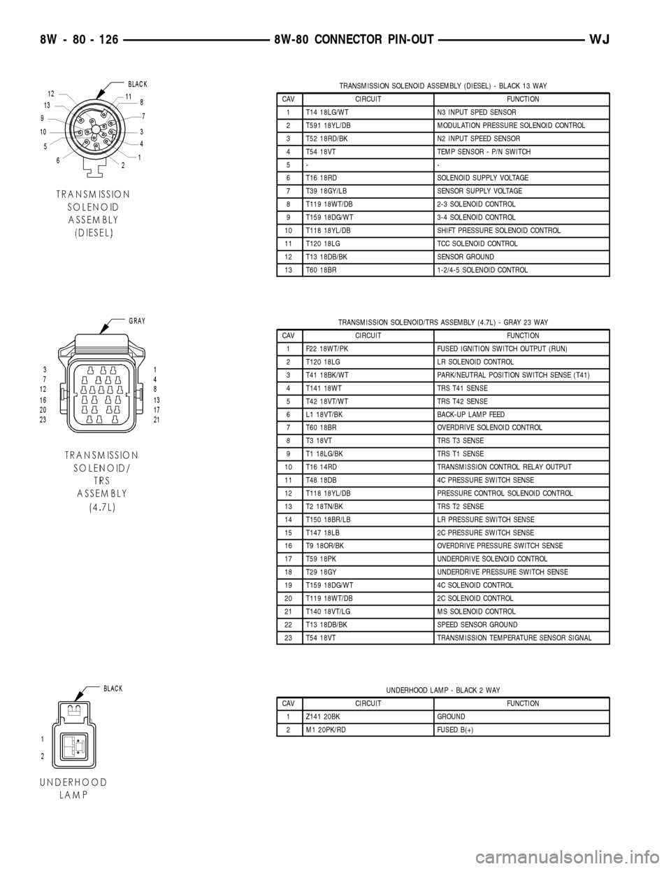
TRANSMISSION SOLENOID ASSEMBLY (DIESEL) - BLACK 13 WAY
CAV CIRCUIT FUNCTION
1 T14 18LG/WT N3 INPUT SPED SENSOR
2 T591 18YL/DB MODULATION PRESSURE SOLENOID CONTROL
3 T52 18RD/BK N2 INPUT SPEED SENSOR
4 T54 18VT TEMP SENSOR - P/N SWITCH
5- -
6 T16 18RD SOLENOID SUPPLY VOLTAGE
7 T39 18GY/LB SENSOR SUPPLY VOLTAGE
8 T119 18WT/DB 2-3 SOLENOID CONTROL
9 T159 18DG/WT 3-4 SOLENOID CONTROL
10 T118 18YL/DB SHIFT PRESSURE SOLENOID CONTROL
11 T120 18LG TCC SOLENOID CONTROL
12 T13 18DB/BK SENSOR GROUND
13 T60 18BR 1-2/4-5 SOLENOID CONTROL
TRANSMISSION SOLENOID/TRS ASSEMBLY (4.7L) - GRAY 23 WAY
CAV CIRCUIT FUNCTION
1 F22 18WT/PK FUSED IGNITION SWITCH OUTPUT (RUN)
2 T120 18LG LR SOLENOID CONTROL
3 T41 18BK/WT PARK/NEUTRAL POSITION SWITCH SENSE (T41)
4 T141 18WT TRS T41 SENSE
5 T42 18VT/WT TRS T42 SENSE
6 L1 18VT/BK BACK-UP LAMP FEED
7 T60 18BR OVERDRIVE SOLENOID CONTROL
8 T3 18VT TRS T3 SENSE
9 T1 18LG/BK TRS T1 SENSE
10 T16 14RD TRANSMISSION CONTROL RELAY OUTPUT
11 T48 18DB 4C PRESSURE SWITCH SENSE
12 T118 18YL/DB PRESSURE CONTROL SOLENOID CONTROL
13 T2 18TN/BK TRS T2 SENSE
14 T150 18BR/LB LR PRESSURE SWITCH SENSE
15 T147 18LB 2C PRESSURE SWITCH SENSE
16 T9 18OR/BK OVERDRIVE PRESSURE SWITCH SENSE
17 T59 18PK UNDERDRIVE SOLENOID CONTROL
18 T29 18GY UNDERDRIVE PRESSURE SWITCH SENSE
19 T159 18DG/WT 4C SOLENOID CONTROL
20 T119 18WT/DB 2C SOLENOID CONTROL
21 T140 18VT/LG MS SOLENOID CONTROL
22 T13 18DB/BK SPEED SENSOR GROUND
23 T54 18VT TRANSMISSION TEMPERATURE SENSOR SIGNAL
UNDERHOOD LAMP - BLACK 2 WAY
CAV CIRCUIT FUNCTION
1 Z141 20BK GROUND
2 M1 20PK/RD FUSED B(+)
8W - 80 - 126 8W-80 CONNECTOR PIN-OUTWJ
Page 1176 of 2199
8W-91 CONNECTOR/GROUND/SPLICE LOCATION
TABLE OF CONTENTS
page
CONNECTOR/GROUND/SPLICE LOCATION
DESCRIPTION..........................1
CONNECTOR/GROUND/SPLICE
LOCATION
DESCRIPTION
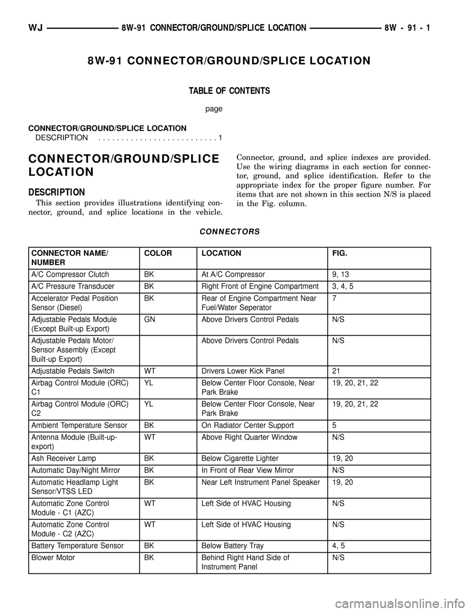
This section provides illustrations identifying con-
nector, ground, and splice locations in the vehicle.Connector, ground, and splice indexes are provided.
Use the wiring diagrams in each section for connec-
tor, ground, and splice identification. Refer to the
appropriate index for the proper figure number. For
items that are not shown in this section N/S is placed
in the Fig. column.
CONNECTORS
CONNECTOR NAME/
NUMBERCOLOR LOCATION FIG.
A/C Compressor Clutch BK At A/C Compressor 9, 13
A/C Pressure Transducer BK Right Front of Engine Compartment 3, 4, 5
Accelerator Pedal Position
Sensor (Diesel)BK Rear of Engine Compartment Near
Fuel/Water Seperator7
Adjustable Pedals Module
(Except Built-up Export)GN Above Drivers Control Pedals N/S
Adjustable Pedals Motor/
Sensor Assembly (Except
Built-up Export)Above Drivers Control Pedals N/S
Adjustable Pedals Switch WT Drivers Lower Kick Panel 21
Airbag Control Module (ORC)
C1YL Below Center Floor Console, Near
Park Brake19, 20, 21, 22
Airbag Control Module (ORC)
C2YL Below Center Floor Console, Near
Park Brake19, 20, 21, 22
Ambient Temperature Sensor BK On Radiator Center Support 5
Antenna Module (Built-up-
export)WT Above Right Quarter Window N/S
Ash Receiver Lamp BK Below Cigarette Lighter 19, 20
Automatic Day/Night Mirror BK In Front of Rear View Mirror N/S
Automatic Headlamp Light
Sensor/VTSS LEDBK Near Left Instrument Panel Speaker 19, 20
Automatic Zone Control
Module - C1 (AZC)WT Left Side of HVAC Housing N/S
Automatic Zone Control
Module - C2 (AZC)WT Left Side of HVAC Housing N/S
Battery Temperature Sensor BK Below Battery Tray 4, 5
Blower Motor BK Behind Right Hand Side of
Instrument PanelN/S
WJ8W-91 CONNECTOR/GROUND/SPLICE LOCATION 8W - 91 - 1
Page 1177 of 2199
CONNECTOR NAME/
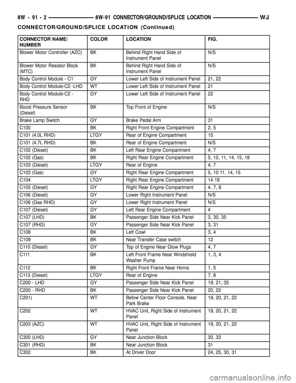
NUMBERCOLOR LOCATION FIG.
Blower Motor Controller (AZC) BK Behind Right Hand Side of
Instrument PanelN/S
Blower Motor Resistor Block
(MTC)BK Behind Right Hand Side of
Instrument PanelN/S
Body Control Module - C1 GY Lower Left Side of Instrument Panel 21, 22
Body Control Module-C2 -LHD WT Lower Left Side of Instrument Panel 21
Body Control Module-C2 -
RHDGY Lower Left Side of Instrument Panel 22
Boost Pressure Sensor
(Diesel)BK Top Front of Engine N/S
Brake Lamp Switch GY Brake Pedal Arm 31
C100 BK Right Front Engine Compartment 2, 5
C101 (4.0L RHD) LTGY Rear of Engine Compartment 15
C101 (4.7L RHD) BK Rear of Engine Compartment N/S
C102 (Diesel) BK Left Rear Engine Compartment 4, 7
C102 (Gas) BK Right Rear Engine Compartment 5, 10, 11, 14, 15, 18
C103 (Diesel) LTGY Rear of Engine 4, 7
C103 (Gas) GY Right Rear Engine Compartment 5, 10 11, 14, 15
C104 LTGY Right Rear Engine Compartment 14 18
C105 (Diesel) GY Right Rear Engine Compartment 4, 7, 8
C106 (Diesel) GY Lower Right Instrument Panel N/S
C106 (Gas RHD) GY Lower Right Instrument Panel N/S
C107 (Diesel) GY Left Rear Engine Compartment 4
C107 (LHD) BK Passenger Side Near Kick Panel 3, 30, 35
C107 (RHD) GY Passenger Side Near Kick Panel 3, 31
C108 BK Left Cowl 3, 4
C109 BK Near Transfer Case switch 12
C110 (Diesel) GY Top of Engine Near Glow Plugs 4, 7
C111 BK Left Front Frame Near Windshield
Washer Pump1, 3, 4
C112 BK Right Front Frame Near Horns 1, 5
C113 (Diesel) LTGY Rear of Engine 7, 8
C200 - LHD GY Passenger Side Near Kick Panel 19, 21, 35
C200 - RHD BK Passenger Side Near Kick Panel 20, 22
C201) WT Below Center Floor Console, Near
Park Brake19, 20, 21, 22
C202 WT HVAC Unit, Right Side of Instrument
Panel19, 20, 21, 22
C203 (AZC) WT HVAC Unit, Right Side of Instrument
Panel19, 20, 21, 22
C300 (LHD) GY Near Junction Block 30, 33
C301 (RHD) BK Near Junction Block 31
C302 BK At Driver Door 24, 25, 30, 31
8W - 91 - 2 8W-91 CONNECTOR/GROUND/SPLICE LOCATIONWJ
CONNECTOR/GROUND/SPLICE LOCATION (Continued)
Page 1181 of 2199
CONNECTOR NAME/
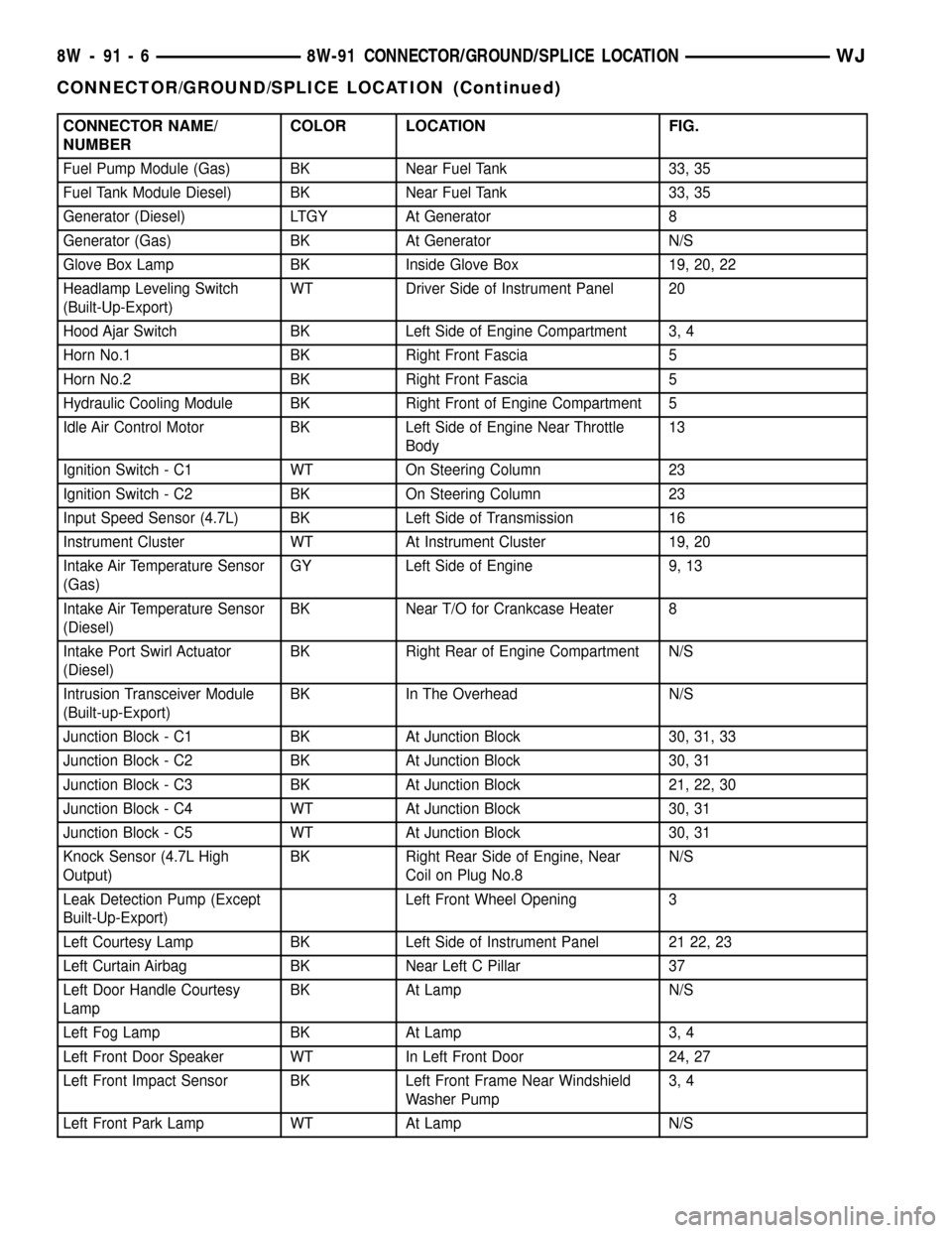
NUMBERCOLOR LOCATION FIG.
Fuel Pump Module (Gas) BK Near Fuel Tank 33, 35
Fuel Tank Module Diesel) BK Near Fuel Tank 33, 35
Generator (Diesel) LTGY At Generator 8
Generator (Gas) BK At Generator N/S
Glove Box Lamp BK Inside Glove Box 19, 20, 22
Headlamp Leveling Switch
(Built-Up-Export)WT Driver Side of Instrument Panel 20
Hood Ajar Switch BK Left Side of Engine Compartment 3, 4
Horn No.1 BK Right Front Fascia 5
Horn No.2 BK Right Front Fascia 5
Hydraulic Cooling Module BK Right Front of Engine Compartment 5
Idle Air Control Motor BK Left Side of Engine Near Throttle
Body13
Ignition Switch - C1 WT On Steering Column 23
Ignition Switch - C2 BK On Steering Column 23
Input Speed Sensor (4.7L) BK Left Side of Transmission 16
Instrument Cluster WT At Instrument Cluster 19, 20
Intake Air Temperature Sensor
(Gas)GY Left Side of Engine 9, 13
Intake Air Temperature Sensor
(Diesel)BK Near T/O for Crankcase Heater 8
Intake Port Swirl Actuator
(Diesel)BK Right Rear of Engine Compartment N/S
Intrusion Transceiver Module
(Built-up-Export)BK In The Overhead N/S
Junction Block - C1 BK At Junction Block 30, 31, 33
Junction Block - C2 BK At Junction Block 30, 31
Junction Block - C3 BK At Junction Block 21, 22, 30
Junction Block - C4 WT At Junction Block 30, 31
Junction Block - C5 WT At Junction Block 30, 31
Knock Sensor (4.7L High
Output)BK Right Rear Side of Engine, Near
Coil on Plug No.8N/S
Leak Detection Pump (Except
Built-Up-Export)Left Front Wheel Opening 3
Left Courtesy Lamp BK Left Side of Instrument Panel 21 22, 23
Left Curtain Airbag BK Near Left C Pillar 37
Left Door Handle Courtesy
LampBK At Lamp N/S
Left Fog Lamp BK At Lamp 3, 4
Left Front Door Speaker WT In Left Front Door 24, 27
Left Front Impact Sensor BK Left Front Frame Near Windshield
Washer Pump3, 4
Left Front Park Lamp WT At Lamp N/S
8W - 91 - 6 8W-91 CONNECTOR/GROUND/SPLICE LOCATIONWJ
CONNECTOR/GROUND/SPLICE LOCATION (Continued)
Page 1182 of 2199
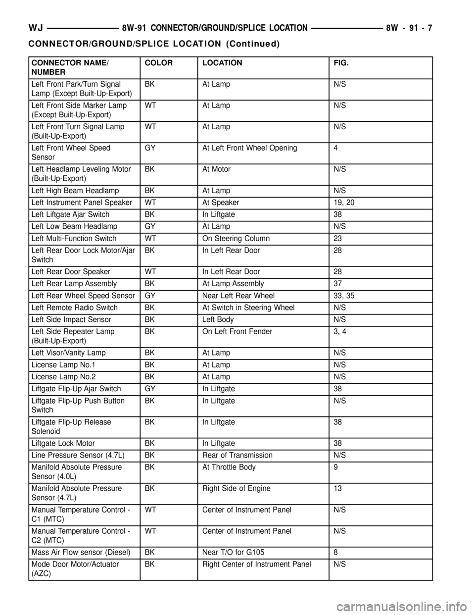
CONNECTOR NAME/
NUMBERCOLOR LOCATION FIG.
Left Front Park/Turn Signal
Lamp (Except Built-Up-Export)BK At Lamp N/S
Left Front Side Marker Lamp
(Except Built-Up-Export)WT At Lamp N/S
Left Front Turn Signal Lamp
(Built-Up-Export)WT At Lamp N/S
Left Front Wheel Speed
SensorGY At Left Front Wheel Opening 4
Left Headlamp Leveling Motor
(Built-Up-Export)BK At Motor N/S
Left High Beam Headlamp BK At Lamp N/S
Left Instrument Panel Speaker WT At Speaker 19, 20
Left Liftgate Ajar Switch BK In Liftgate 38
Left Low Beam Headlamp GY At Lamp N/S
Left Multi-Function Switch WT On Steering Column 23
Left Rear Door Lock Motor/Ajar
SwitchBK In Left Rear Door 28
Left Rear Door Speaker WT In Left Rear Door 28
Left Rear Lamp Assembly BK At Lamp Assembly 37
Left Rear Wheel Speed Sensor GY Near Left Rear Wheel 33, 35
Left Remote Radio Switch BK At Switch in Steering Wheel N/S
Left Side Impact Sensor BK Left Body N/S
Left Side Repeater Lamp
(Built-Up-Export)BK On Left Front Fender 3, 4
Left Visor/Vanity Lamp BK At Lamp N/S
License Lamp No.1 BK At Lamp N/S
License Lamp No.2 BK At Lamp N/S
Liftgate Flip-Up Ajar Switch GY In Liftgate 38
Liftgate Flip-Up Push Button
SwitchBK In Liftgate N/S
Liftgate Flip-Up Release
SolenoidBK In Liftgate 38
Liftgate Lock Motor BK In Liftgate 38
Line Pressure Sensor (4.7L) BK Rear of Transmission N/S
Manifold Absolute Pressure
Sensor (4.0L)BK At Throttle Body 9
Manifold Absolute Pressure
Sensor (4.7L)BK Right Side of Engine 13
Manual Temperature Control -
C1 (MTC)WT Center of Instrument Panel N/S
Manual Temperature Control -
C2 (MTC)WT Center of Instrument Panel N/S
Mass Air Flow sensor (Diesel) BK Near T/O for G105 8
Mode Door Motor/Actuator
(AZC)BK Right Center of Instrument Panel N/S
WJ8W-91 CONNECTOR/GROUND/SPLICE LOCATION 8W - 91 - 7
CONNECTOR/GROUND/SPLICE LOCATION (Continued)
Page 1183 of 2199
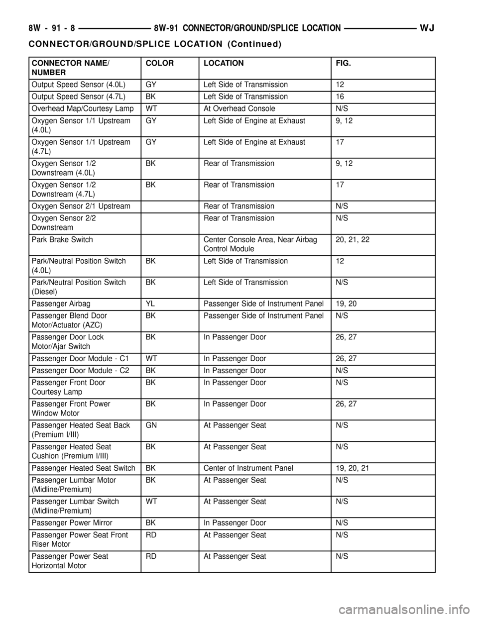
CONNECTOR NAME/
NUMBERCOLOR LOCATION FIG.
Output Speed Sensor (4.0L) GY Left Side of Transmission 12
Output Speed Sensor (4.7L) BK Left Side of Transmission 16
Overhead Map/Courtesy Lamp WT At Overhead Console N/S
Oxygen Sensor 1/1 Upstream
(4.0L)GY Left Side of Engine at Exhaust 9, 12
Oxygen Sensor 1/1 Upstream
(4.7L)GY Left Side of Engine at Exhaust 17
Oxygen Sensor 1/2
Downstream (4.0L)BK Rear of Transmission 9, 12
Oxygen Sensor 1/2
Downstream (4.7L)BK Rear of Transmission 17
Oxygen Sensor 2/1 Upstream Rear of Transmission N/S
Oxygen Sensor 2/2
DownstreamRear of Transmission N/S
Park Brake Switch Center Console Area, Near Airbag
Control Module20, 21, 22
Park/Neutral Position Switch
(4.0L)BK Left Side of Transmission 12
Park/Neutral Position Switch
(Diesel)BK Left Side of Transmission N/S
Passenger Airbag YL Passenger Side of Instrument Panel 19, 20
Passenger Blend Door
Motor/Actuator (AZC)BK Passenger Side of Instrument Panel N/S
Passenger Door Lock
Motor/Ajar SwitchBK In Passenger Door 26, 27
Passenger Door Module - C1 WT In Passenger Door 26, 27
Passenger Door Module - C2 BK In Passenger Door N/S
Passenger Front Door
Courtesy LampBK In Passenger Door N/S
Passenger Front Power
Window MotorBK In Passenger Door 26, 27
Passenger Heated Seat Back
(Premium I/III)GN At Passenger Seat N/S
Passenger Heated Seat
Cushion (Premium I/III)BK At Passenger Seat N/S
Passenger Heated Seat Switch BK Center of Instrument Panel 19, 20, 21
Passenger Lumbar Motor
(Midline/Premium)BK At Passenger Seat N/S
Passenger Lumbar Switch
(Midline/Premium)WT At Passenger Seat N/S
Passenger Power Mirror BK In Passenger Door N/S
Passenger Power Seat Front
Riser MotorRD At Passenger Seat N/S
Passenger Power Seat
Horizontal MotorRD At Passenger Seat N/S
8W - 91 - 8 8W-91 CONNECTOR/GROUND/SPLICE LOCATIONWJ
CONNECTOR/GROUND/SPLICE LOCATION (Continued)
Page 1184 of 2199
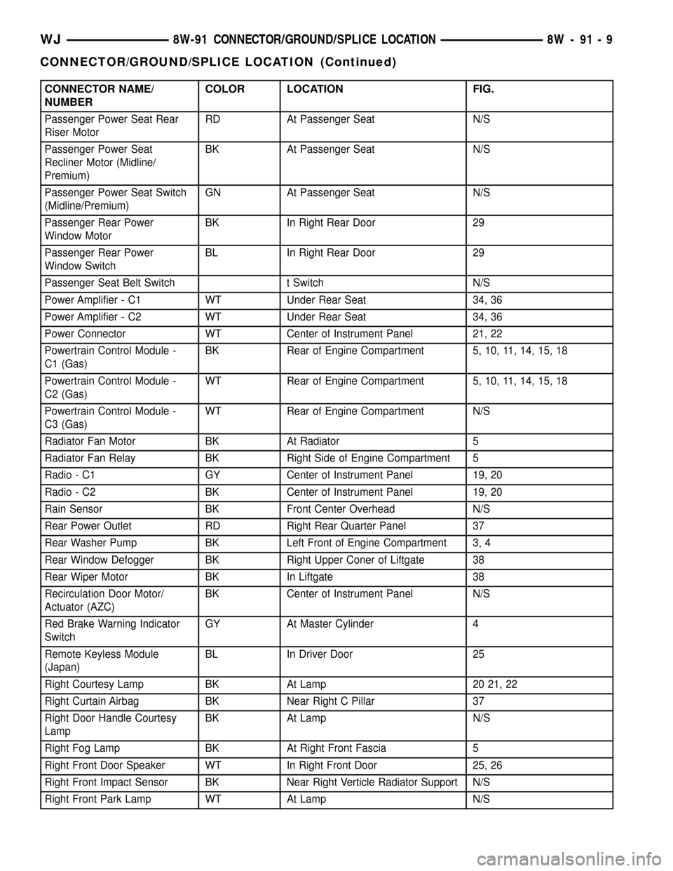
CONNECTOR NAME/
NUMBERCOLOR LOCATION FIG.
Passenger Power Seat Rear
Riser MotorRD At Passenger Seat N/S
Passenger Power Seat
Recliner Motor (Midline/
Premium)BK At Passenger Seat N/S
Passenger Power Seat Switch
(Midline/Premium)GN At Passenger Seat N/S
Passenger Rear Power
Window MotorBK In Right Rear Door 29
Passenger Rear Power
Window SwitchBL In Right Rear Door 29
Passenger Seat Belt Switch t Switch N/S
Power Amplifier - C1 WT Under Rear Seat 34, 36
Power Amplifier - C2 WT Under Rear Seat 34, 36
Power Connector WT Center of Instrument Panel 21, 22
Powertrain Control Module -
C1 (Gas)BK Rear of Engine Compartment 5, 10, 11, 14, 15, 18
Powertrain Control Module -
C2 (Gas)WT Rear of Engine Compartment 5, 10, 11, 14, 15, 18
Powertrain Control Module -
C3 (Gas)WT Rear of Engine Compartment N/S
Radiator Fan Motor BK At Radiator 5
Radiator Fan Relay BK Right Side of Engine Compartment 5
Radio - C1 GY Center of Instrument Panel 19, 20
Radio - C2 BK Center of Instrument Panel 19, 20
Rain Sensor BK Front Center Overhead N/S
Rear Power Outlet RD Right Rear Quarter Panel 37
Rear Washer Pump BK Left Front of Engine Compartment 3, 4
Rear Window Defogger BK Right Upper Coner of Liftgate 38
Rear Wiper Motor BK In Liftgate 38
Recirculation Door Motor/
Actuator (AZC)BK Center of Instrument Panel N/S
Red Brake Warning Indicator
SwitchGY At Master Cylinder 4
Remote Keyless Module
(Japan)BL In Driver Door 25
Right Courtesy Lamp BK At Lamp 20 21, 22
Right Curtain Airbag BK Near Right C Pillar 37
Right Door Handle Courtesy
LampBK At Lamp N/S
Right Fog Lamp BK At Right Front Fascia 5
Right Front Door Speaker WT In Right Front Door 25, 26
Right Front Impact Sensor BK Near Right Verticle Radiator Support N/S
Right Front Park Lamp WT At Lamp N/S
WJ8W-91 CONNECTOR/GROUND/SPLICE LOCATION 8W - 91 - 9
CONNECTOR/GROUND/SPLICE LOCATION (Continued)
Page 1185 of 2199
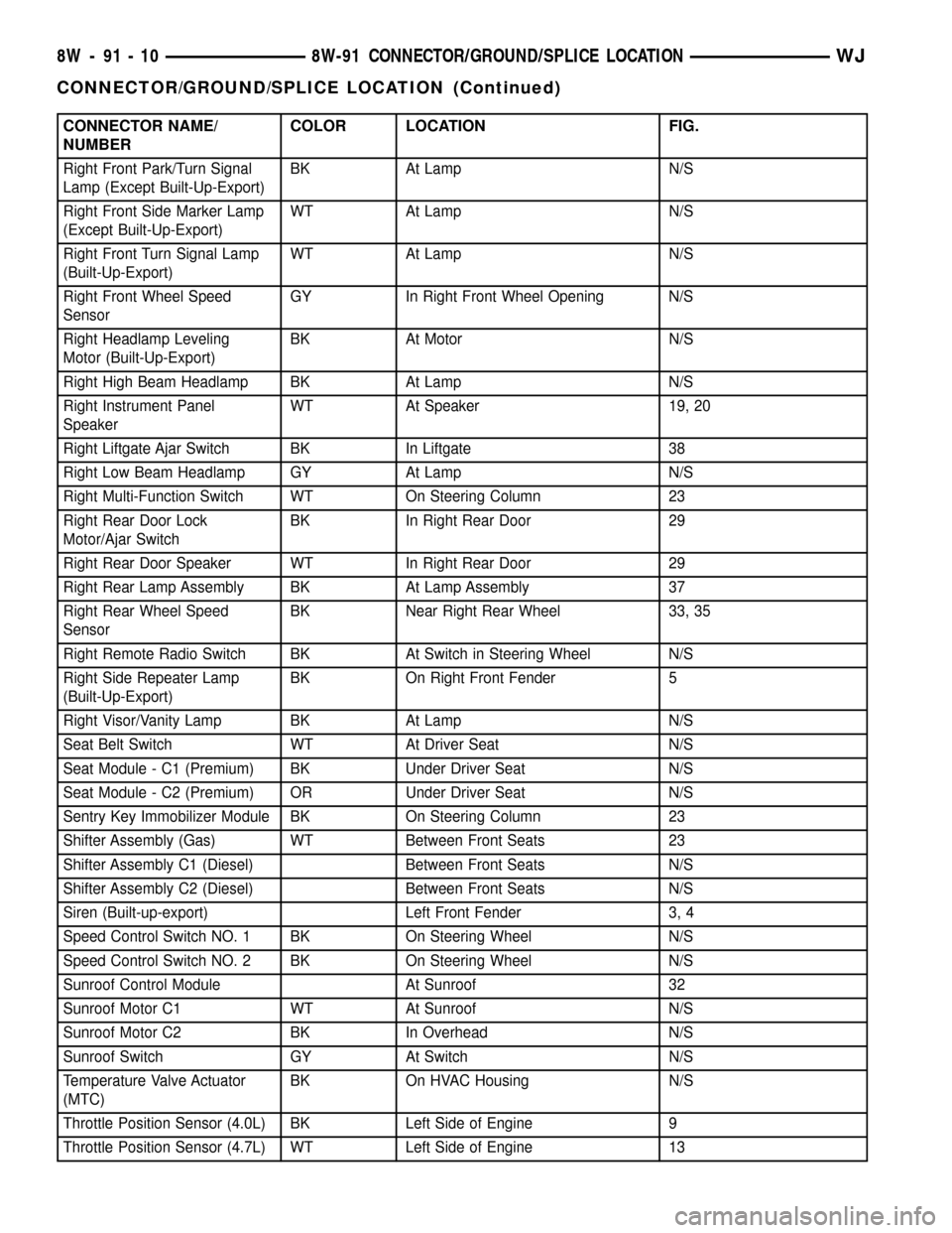
CONNECTOR NAME/
NUMBERCOLOR LOCATION FIG.
Right Front Park/Turn Signal
Lamp (Except Built-Up-Export)BK At Lamp N/S
Right Front Side Marker Lamp
(Except Built-Up-Export)WT At Lamp N/S
Right Front Turn Signal Lamp
(Built-Up-Export)WT At Lamp N/S
Right Front Wheel Speed
SensorGY In Right Front Wheel Opening N/S
Right Headlamp Leveling
Motor (Built-Up-Export)BK At Motor N/S
Right High Beam Headlamp BK At Lamp N/S
Right Instrument Panel
SpeakerWT At Speaker 19, 20
Right Liftgate Ajar Switch BK In Liftgate 38
Right Low Beam Headlamp GY At Lamp N/S
Right Multi-Function Switch WT On Steering Column 23
Right Rear Door Lock
Motor/Ajar SwitchBK In Right Rear Door 29
Right Rear Door Speaker WT In Right Rear Door 29
Right Rear Lamp Assembly BK At Lamp Assembly 37
Right Rear Wheel Speed
SensorBK Near Right Rear Wheel 33, 35
Right Remote Radio Switch BK At Switch in Steering Wheel N/S
Right Side Repeater Lamp
(Built-Up-Export)BK On Right Front Fender 5
Right Visor/Vanity Lamp BK At Lamp N/S
Seat Belt Switch WT At Driver Seat N/S
Seat Module - C1 (Premium) BK Under Driver Seat N/S
Seat Module - C2 (Premium) OR Under Driver Seat N/S
Sentry Key Immobilizer Module BK On Steering Column 23
Shifter Assembly (Gas) WT Between Front Seats 23
Shifter Assembly C1 (Diesel) Between Front Seats N/S
Shifter Assembly C2 (Diesel) Between Front Seats N/S
Siren (Built-up-export) Left Front Fender 3, 4
Speed Control Switch NO. 1 BK On Steering Wheel N/S
Speed Control Switch NO. 2 BK On Steering Wheel N/S
Sunroof Control Module At Sunroof 32
Sunroof Motor C1 WT At Sunroof N/S
Sunroof Motor C2 BK In Overhead N/S
Sunroof Switch GY At Switch N/S
Temperature Valve Actuator
(MTC)BK On HVAC Housing N/S
Throttle Position Sensor (4.0L) BK Left Side of Engine 9
Throttle Position Sensor (4.7L) WT Left Side of Engine 13
8W - 91 - 10 8W-91 CONNECTOR/GROUND/SPLICE LOCATIONWJ
CONNECTOR/GROUND/SPLICE LOCATION (Continued)
Page 1247 of 2199
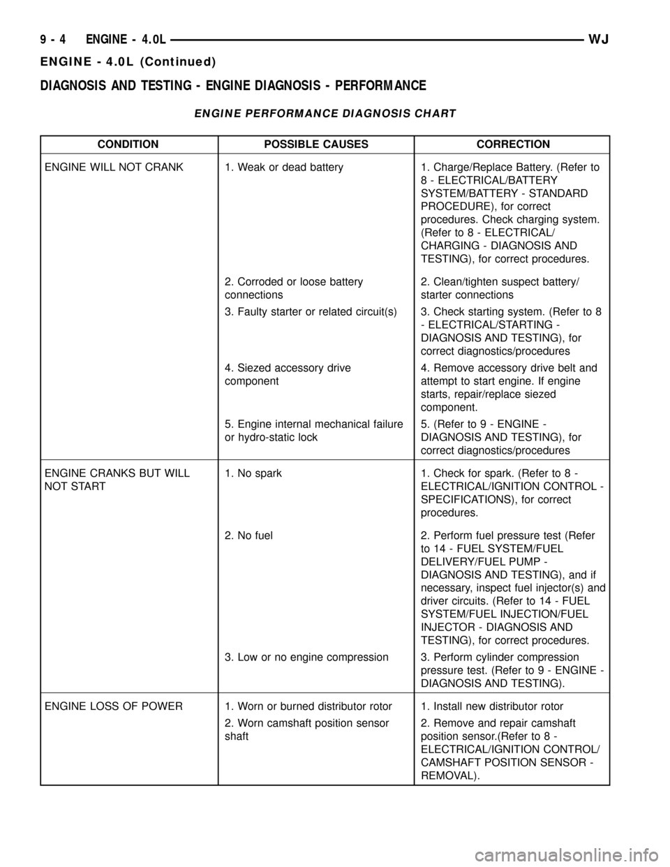
DIAGNOSIS AND TESTING - ENGINE DIAGNOSIS - PERFORMANCE
ENGINE PERFORMANCE DIAGNOSIS CHART
CONDITION POSSIBLE CAUSES CORRECTION
ENGINE WILL NOT CRANK 1. Weak or dead battery 1. Charge/Replace Battery. (Refer to
8 - ELECTRICAL/BATTERY
SYSTEM/BATTERY - STANDARD
PROCEDURE), for correct
procedures. Check charging system.
(Refer to 8 - ELECTRICAL/
CHARGING - DIAGNOSIS AND
TESTING), for correct procedures.
2. Corroded or loose battery
connections2. Clean/tighten suspect battery/
starter connections
3. Faulty starter or related circuit(s) 3. Check starting system. (Refer to 8
- ELECTRICAL/STARTING -
DIAGNOSIS AND TESTING), for
correct diagnostics/procedures
4. Siezed accessory drive
component4. Remove accessory drive belt and
attempt to start engine. If engine
starts, repair/replace siezed
component.
5. Engine internal mechanical failure
or hydro-static lock5. (Refer to 9 - ENGINE -
DIAGNOSIS AND TESTING), for
correct diagnostics/procedures
ENGINE CRANKS BUT WILL
NOT START1. No spark 1. Check for spark. (Refer to 8 -
ELECTRICAL/IGNITION CONTROL -
SPECIFICATIONS), for correct
procedures.
2. No fuel 2. Perform fuel pressure test (Refer
to 14 - FUEL SYSTEM/FUEL
DELIVERY/FUEL PUMP -
DIAGNOSIS AND TESTING), and if
necessary, inspect fuel injector(s) and
driver circuits. (Refer to 14 - FUEL
SYSTEM/FUEL INJECTION/FUEL
INJECTOR - DIAGNOSIS AND
TESTING), for correct procedures.
3. Low or no engine compression 3. Perform cylinder compression
pressure test. (Refer to 9 - ENGINE -
DIAGNOSIS AND TESTING).
ENGINE LOSS OF POWER 1. Worn or burned distributor rotor 1. Install new distributor rotor
2. Worn camshaft position sensor
shaft2. Remove and repair camshaft
position sensor.(Refer to 8 -
ELECTRICAL/IGNITION CONTROL/
CAMSHAFT POSITION SENSOR -
REMOVAL).
9 - 4 ENGINE - 4.0LWJ
ENGINE - 4.0L (Continued)
Page 1311 of 2199
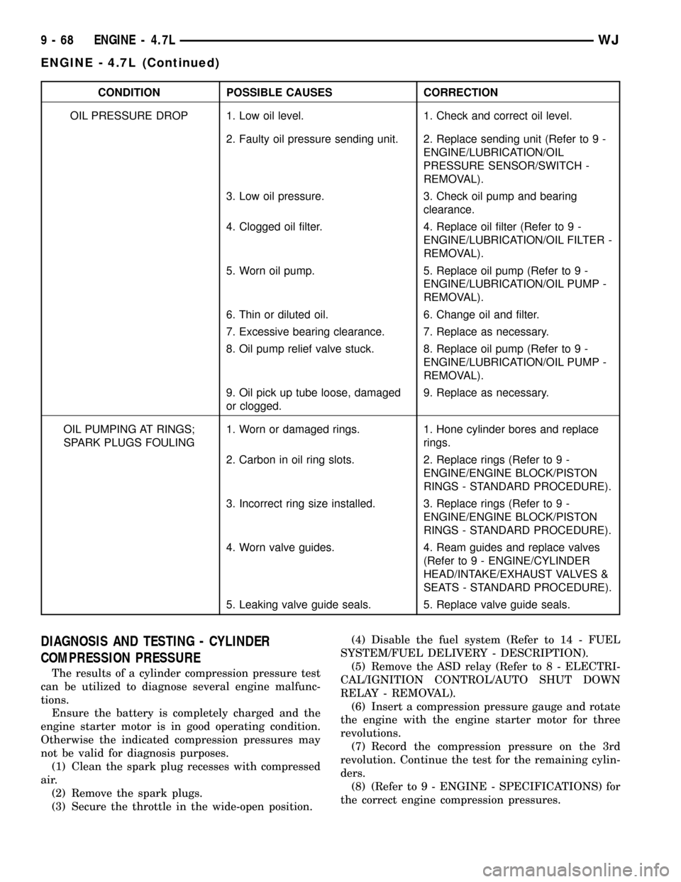
CONDITION POSSIBLE CAUSES CORRECTION
OIL PRESSURE DROP 1. Low oil level. 1. Check and correct oil level.
2. Faulty oil pressure sending unit. 2. Replace sending unit (Refer to 9 -
ENGINE/LUBRICATION/OIL
PRESSURE SENSOR/SWITCH -
REMOVAL).
3. Low oil pressure. 3. Check oil pump and bearing
clearance.
4. Clogged oil filter. 4. Replace oil filter (Refer to 9 -
ENGINE/LUBRICATION/OIL FILTER -
REMOVAL).
5. Worn oil pump. 5. Replace oil pump (Refer to 9 -
ENGINE/LUBRICATION/OIL PUMP -
REMOVAL).
6. Thin or diluted oil. 6. Change oil and filter.
7. Excessive bearing clearance. 7. Replace as necessary.
8. Oil pump relief valve stuck. 8. Replace oil pump (Refer to 9 -
ENGINE/LUBRICATION/OIL PUMP -
REMOVAL).
9. Oil pick up tube loose, damaged
or clogged.9. Replace as necessary.
OIL PUMPING AT RINGS;
SPARK PLUGS FOULING1. Worn or damaged rings. 1. Hone cylinder bores and replace
rings.
2. Carbon in oil ring slots. 2. Replace rings (Refer to 9 -
ENGINE/ENGINE BLOCK/PISTON
RINGS - STANDARD PROCEDURE).
3. Incorrect ring size installed. 3. Replace rings (Refer to 9 -
ENGINE/ENGINE BLOCK/PISTON
RINGS - STANDARD PROCEDURE).
4. Worn valve guides. 4. Ream guides and replace valves
(Refer to 9 - ENGINE/CYLINDER
HEAD/INTAKE/EXHAUST VALVES &
SEATS - STANDARD PROCEDURE).
5. Leaking valve guide seals. 5. Replace valve guide seals.
DIAGNOSIS AND TESTING - CYLINDER
COMPRESSION PRESSURE
The results of a cylinder compression pressure test
can be utilized to diagnose several engine malfunc-
tions.
Ensure the battery is completely charged and the
engine starter motor is in good operating condition.
Otherwise the indicated compression pressures may
not be valid for diagnosis purposes.
(1) Clean the spark plug recesses with compressed
air.
(2) Remove the spark plugs.
(3) Secure the throttle in the wide-open position.(4) Disable the fuel system (Refer to 14 - FUEL
SYSTEM/FUEL DELIVERY - DESCRIPTION).
(5) Remove the ASD relay (Refer to 8 - ELECTRI-
CAL/IGNITION CONTROL/AUTO SHUT DOWN
RELAY - REMOVAL).
(6) Insert a compression pressure gauge and rotate
the engine with the engine starter motor for three
revolutions.
(7) Record the compression pressure on the 3rd
revolution. Continue the test for the remaining cylin-
ders.
(8) (Refer to 9 - ENGINE - SPECIFICATIONS) for
the correct engine compression pressures.
9 - 68 ENGINE - 4.7LWJ
ENGINE - 4.7L (Continued)