Control arm JEEP GRAND CHEROKEE 2002 WJ / 2.G Manual Online
[x] Cancel search | Manufacturer: JEEP, Model Year: 2002, Model line: GRAND CHEROKEE, Model: JEEP GRAND CHEROKEE 2002 WJ / 2.GPages: 2199, PDF Size: 76.01 MB
Page 1524 of 2199

IDENTIFICATION
Transmission identification numbers are stamped
on the left side of the case just above the oil pan gas-
ket surface (Fig. 2). Refer to this information when
ordering replacement parts.
GEAR RATIOS The 42RE gear ratios are:
1st.................................2.74:1
2nd................................1.54:1
3rd.................................1.00:1
4th.................................0.69:1
Rev.................................2.21:1
OPERATION
The application of each driving or holding compo-
nent is controlled by the valve body based upon the
manual lever position, throttle pressure, and gover-
nor pressure. The governor pressure is a variable
pressure input to the valve body and is one of the
signals that a shift is necessary. First through fourth
gear are obtained by selectively applying and releas-
ing the different clutches and bands. Engine power is
thereby routed to the various planetary gear assem-
blies which combine with the overrunning clutch
assemblies to generate the different gear ratios. The
torque converter clutch is hydraulically applied and
is released when fluid is vented from the hydraulic
circuit by the torque converter control (TCC) solenoid
on the valve body. The torque converter clutch is con-
trolled by the Powertrain Control Module (PCM). The
torque converter clutch engages in fourth gear, and
in third gear under various conditions, such as when
the O/D switch is OFF, when the vehicle is cruising
on a level surface after the vehicle has warmed up.
The torque converter clutch will disengage momen-
tarily when an increase in engine load is sensed by
the PCM, such as when the vehicle begins to go
uphill or the throttle pressure is increased. The
torque converter clutch feature increases fuel econ-
omy and reduces the transmission fluid temperature.
Since the overdrive clutch is applied in fourth gear
only and the direct clutch is applied in all ranges
except fourth gear, the transmission operation for
park, neutral, and first through third gear will be
described first. Once these powerflows are described,
the third to fourth shift sequence will be described.
1 - CONVERTER CLUTCH 15 - HOUSING
2 - TORQUE CONVERTER 16 - REAR BEARING
3 - OIL PUMP AND REACTION SHAFT SUPPORT ASSEMBLY 17 - OUTPUT SHAFT
4 - FRONT BAND 18 - SEAL
5 - FRONT CLUTCH 19 - OVERDRIVE OVERRUNNING CLUTCH
6 - DRIVING SHELL 20 - OVERDRIVE PLANETARY GEAR
7 - REAR BAND 21 - DIRECT CLUTCH SPRING
8 - TRANSMISSION OVERRUNNING CLUTCH 22 - OVERDRIVE CLUTCH PISTON
9 - OVERDRIVE UNIT 23 - VALVE BODY ASSEMBLY
10 - PISTON RETAINER 24 - FILTER
11 - OVERDRIVE CLUTCH 25 - FRONT PLANETARY GEAR
12 - DIRECT CLUTCH 26 - REAR CLUTCH
13 - INTERMEDIATE SHAFT 27 - TRANSMISSION
14 - FRONT BEARING 28 - REAR PLANETARY GEAR
Fig. 2 Transmission Part And Serial Number
Location
1 - PART NUMBER
2 - BUILD DATE
3 - SERIAL NUMBER
WJAUTOMATIC TRANSMISSION - 42RE 21 - 5
AUTOMATIC TRANSMISSION - 42RE (Continued)
Page 1536 of 2199

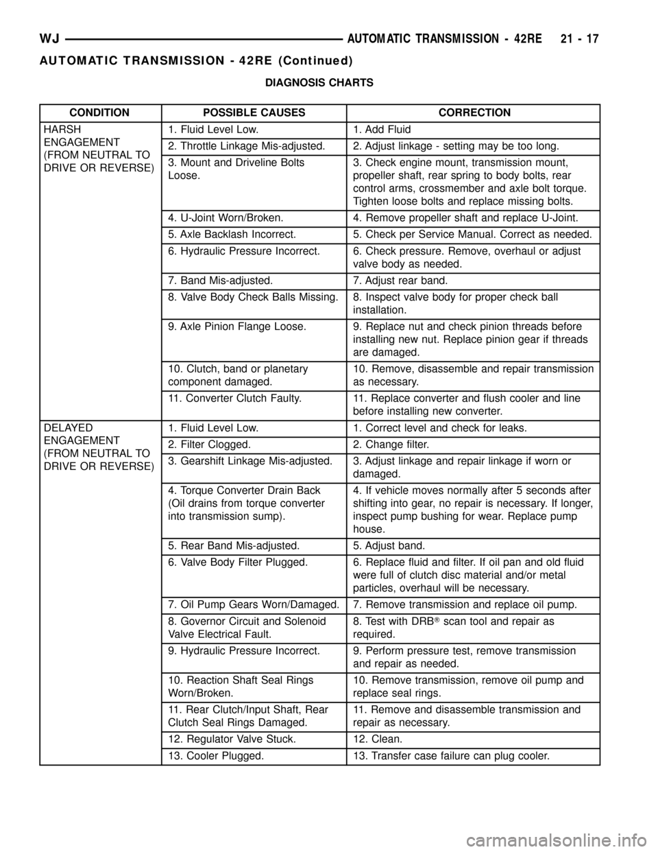
DIAGNOSIS CHARTS
CONDITION POSSIBLE CAUSES CORRECTION
HARSH
ENGAGEMENT
(FROM NEUTRAL TO
DRIVE OR REVERSE)1. Fluid Level Low. 1. Add Fluid
2. Throttle Linkage Mis-adjusted. 2. Adjust linkage - setting may be too long.
3. Mount and Driveline Bolts
Loose.3. Check engine mount, transmission mount,
propeller shaft, rear spring to body bolts, rear
control arms, crossmember and axle bolt torque.
Tighten loose bolts and replace missing bolts.
4. U-Joint Worn/Broken. 4. Remove propeller shaft and replace U-Joint.
5. Axle Backlash Incorrect. 5. Check per Service Manual. Correct as needed.
6. Hydraulic Pressure Incorrect. 6. Check pressure. Remove, overhaul or adjust
valve body as needed.
7. Band Mis-adjusted. 7. Adjust rear band.
8. Valve Body Check Balls Missing. 8. Inspect valve body for proper check ball
installation.
9. Axle Pinion Flange Loose. 9. Replace nut and check pinion threads before
installing new nut. Replace pinion gear if threads
are damaged.
10. Clutch, band or planetary
component damaged.10. Remove, disassemble and repair transmission
as necessary.
11. Converter Clutch Faulty. 11. Replace converter and flush cooler and line
before installing new converter.
DELAYED
ENGAGEMENT
(FROM NEUTRAL TO
DRIVE OR REVERSE)1. Fluid Level Low. 1. Correct level and check for leaks.
2. Filter Clogged. 2. Change filter.
3. Gearshift Linkage Mis-adjusted. 3. Adjust linkage and repair linkage if worn or
damaged.
4. Torque Converter Drain Back
(Oil drains from torque converter
into transmission sump).4. If vehicle moves normally after 5 seconds after
shifting into gear, no repair is necessary. If longer,
inspect pump bushing for wear. Replace pump
house.
5. Rear Band Mis-adjusted. 5. Adjust band.
6. Valve Body Filter Plugged. 6. Replace fluid and filter. If oil pan and old fluid
were full of clutch disc material and/or metal
particles, overhaul will be necessary.
7. Oil Pump Gears Worn/Damaged. 7. Remove transmission and replace oil pump.
8. Governor Circuit and Solenoid
Valve Electrical Fault.8. Test with DRBTscan tool and repair as
required.
9. Hydraulic Pressure Incorrect. 9. Perform pressure test, remove transmission
and repair as needed.
10. Reaction Shaft Seal Rings
Worn/Broken.10. Remove transmission, remove oil pump and
replace seal rings.
11. Rear Clutch/Input Shaft, Rear
Clutch Seal Rings Damaged.11. Remove and disassemble transmission and
repair as necessary.
12. Regulator Valve Stuck. 12. Clean.
13. Cooler Plugged. 13. Transfer case failure can plug cooler.
WJAUTOMATIC TRANSMISSION - 42RE 21 - 17
AUTOMATIC TRANSMISSION - 42RE (Continued)
Page 1645 of 2199

A solenoid can also be described by the method by
which it is controlled. Some of the possibilities
include variable force, pulse-width modulated, con-
stant ON, or duty cycle. The variable force and pulse-
width modulated versions utilize similar methods to
control the current flow through the solenoid to posi-
tion the solenoid plunger at a desired position some-
where between full ON and full OFF. The constant
ON and duty cycled versions control the voltage
across the solenoid to allow either full flow or no flow
through the solenoid's valve.
OPERATION
When an electrical current is applied to the sole-
noid coil, a magnetic field is created which produces
an attraction to the plunger, causing the plunger to
move and work against the spring pressure and the
load applied by the fluid the valve is controlling. The
plunger is normally directly attached to the valve
which it is to operate. When the current is removed
from the coil, the attraction is removed and the
plunger will return to its original position due to
spring pressure.
The plunger is made of a conductive material and
accomplishes this movement by providing a path for
the magnetic field to flow. By keeping the air gap
between the plunger and the coil to the minimum
necessary to allow free movement of the plunger, the
magnetic field is maximized.
SPEED SENSOR
DESCRIPTION
The speed sensor (Fig. 240) is located in the over-
drive gear case. The sensor is positioned over the
park gear and monitors transmission output shaft
rotating speed.
OPERATION
Speed sensor signals are triggered by the park
gear lugs as they rotate past the sensor pickup face.
Input signals from the sensor are sent to the trans-
mission control module for processing. Signals from
this sensor are shared with the powertrain control
module.
THROTTLE VALVE CABLE
DESCRIPTION
Transmission throttle valve cable adjustment is
extremely important to proper operation. This adjust-
ment positions the throttle valve, which controls shift
speed, quality, and part-throttle downshift sensitivity.
If cable setting is too loose, early shifts and slip-
page between shifts may occur. If the setting is too
tight, shifts may be delayed and part throttle down-
shifts may be very sensitive.
The transmission throttle valve is operated by a
cam on the throttle lever. The throttle lever is oper-
ated by an adjustable cable (Fig. 241). The cable is
attached to an arm mounted on the throttle lever
shaft. A retaining clip at the engine-end of the cable
is removed to provide for cable adjustment. The
retaining clip is then installed back onto the throttle
valve cable to lock in the adjustment.
ADJUSTMENTS - TRANSMISSION THROTTLE
VALVE CABLE
A correctly adjusted throttle valve cable (Fig. 242)
will cause the throttle lever on the transmission to
move simultaneously with the throttle body lever
from the idle position. Proper adjustment will allow
Fig. 240 Transmission Output Speed Sensor
1 - TRANSMISSION OUTPUT SHAFT SPEED SENSOR
2 - SEAL
Fig. 241 Throttle Valve Cable
1 - THROTTLE VALVE CABLE
2 - THROTTLE VALVE LEVER
3 - THROTTLE BODY
21 - 126 AUTOMATIC TRANSMISSION - 42REWJ
SOLENOID (Continued)
Page 1652 of 2199

TORQUE CONVERTER CLUTCH (TCC)
The torque converter clutch is hydraulically
applied and is released when fluid is vented from the
hydraulic circuit by the torque converter control
(TCC) solenoid on the valve body. The torque con-
verter clutch is controlled by the Powertrain Control
Module (PCM). The torque converter clutch engages
in fourth gear, and in third gear under various con-
ditions, such as when the O/D switch is OFF, when
the vehicle is cruising on a level surface after the
vehicle has warmed up. The torque converter clutch
will disengage momentarily when an increase in
engine load is sensed by the PCM, such as when the
vehicle begins to go uphill or the throttle pressure is
increased.
REMOVAL
(1) Remove transmission and torque converter
from vehicle.
(2) Place a suitable drain pan under the converter
housing end of the transmission.
CAUTION: Verify that transmission is secure on the
lifting device or work surface, the center of gravity
of the transmission will shift when the torque con-
verter is removed creating an unstable condition.
The torque converter is a heavy unit. Use caution
when separating the torque converter from the
transmission.
(3) Pull the torque converter forward until the cen-
ter hub clears the oil pump seal.
(4) Separate the torque converter from the trans-
mission.
INSTALLATION
Check converter hub and drive notches for sharp
edges, burrs, scratches, or nicks. Polish the hub and
notches with 320/400 grit paper or crocus cloth if nec-
essary. The hub must be smooth to avoid damaging
the pump seal at installation.
(1) Lubricate oil pump seal lip with transmission
fluid.
(2) Place torque converter in position on transmis-
sion.
CAUTION: Do not damage oil pump seal or bushing
while inserting torque converter into the front of the
transmission.
(3) Align torque converter to oil pump seal open-
ing.
(4) Insert torque converter hub into oil pump.
(5) While pushing torque converter inward, rotate
converter until converter is fully seated in the oil
pump gears.
(6) Check converter seating with a scale and
straightedge (Fig. 253). Surface of converter lugs
should be 1/2 in. to rear of straightedge when con-
verter is fully seated.
(7) If necessary, temporarily secure converter with
C-clamp attached to the converter housing.
(8) Install the transmission in the vehicle.
(9) Fill the transmission with the recommended
fluid.
Fig. 252 Stator Operation
1 - DIRECTION STATOR WILL FREE WHEEL DUE TO OIL
PUSHING ON BACKSIDE OF VANES
2 - FRONT OF ENGINE
3 - INCREASED ANGLE AS OIL STRIKES VANES
4 - DIRECTION STATOR IS LOCKED UP DUE TO OIL PUSHING
AGAINST STATOR VANES
Fig. 253 Checking Torque Converter Seating -
Typical
1 - SCALE
2 - STRAIGHTEDGE
WJAUTOMATIC TRANSMISSION - 42RE 21 - 133
TORQUE CONVERTER (Continued)
Page 2026 of 2199

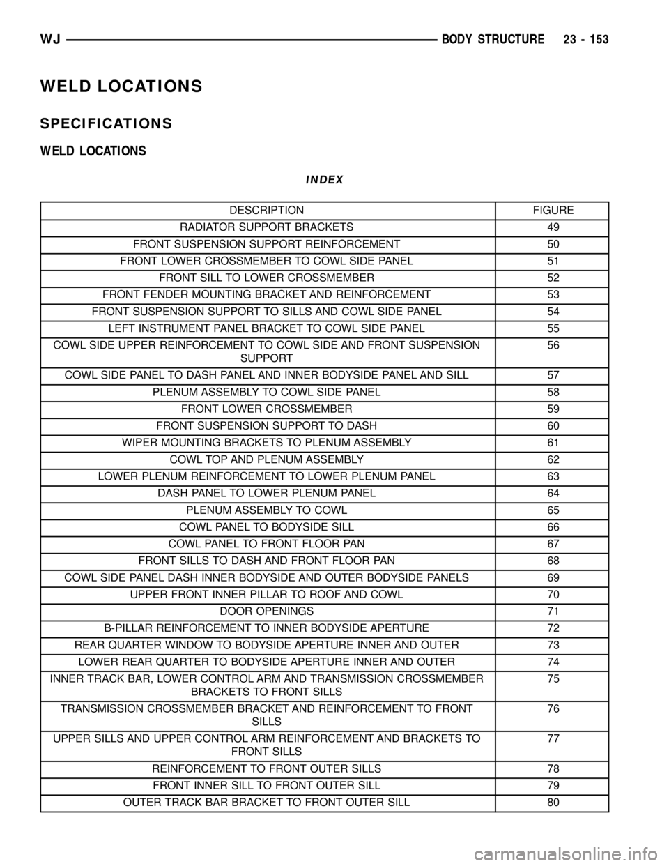
WELD LOCATIONS
SPECIFICATIONS
WELD LOCATIONS
INDEX
DESCRIPTION FIGURE
RADIATOR SUPPORT BRACKETS 49
FRONT SUSPENSION SUPPORT REINFORCEMENT 50
FRONT LOWER CROSSMEMBER TO COWL SIDE PANEL 51
FRONT SILL TO LOWER CROSSMEMBER 52
FRONT FENDER MOUNTING BRACKET AND REINFORCEMENT 53
FRONT SUSPENSION SUPPORT TO SILLS AND COWL SIDE PANEL 54
LEFT INSTRUMENT PANEL BRACKET TO COWL SIDE PANEL 55
COWL SIDE UPPER REINFORCEMENT TO COWL SIDE AND FRONT SUSPENSION
SUPPORT56
COWL SIDE PANEL TO DASH PANEL AND INNER BODYSIDE PANEL AND SILL 57
PLENUM ASSEMBLY TO COWL SIDE PANEL 58
FRONT LOWER CROSSMEMBER 59
FRONT SUSPENSION SUPPORT TO DASH 60
WIPER MOUNTING BRACKETS TO PLENUM ASSEMBLY 61
COWL TOP AND PLENUM ASSEMBLY 62
LOWER PLENUM REINFORCEMENT TO LOWER PLENUM PANEL 63
DASH PANEL TO LOWER PLENUM PANEL 64
PLENUM ASSEMBLY TO COWL 65
COWL PANEL TO BODYSIDE SILL 66
COWL PANEL TO FRONT FLOOR PAN 67
FRONT SILLS TO DASH AND FRONT FLOOR PAN 68
COWL SIDE PANEL DASH INNER BODYSIDE AND OUTER BODYSIDE PANELS 69
UPPER FRONT INNER PILLAR TO ROOF AND COWL 70
DOOR OPENINGS 71
B-PILLAR REINFORCEMENT TO INNER BODYSIDE APERTURE 72
REAR QUARTER WINDOW TO BODYSIDE APERTURE INNER AND OUTER 73
LOWER REAR QUARTER TO BODYSIDE APERTURE INNER AND OUTER 74
INNER TRACK BAR, LOWER CONTROL ARM AND TRANSMISSION CROSSMEMBER
BRACKETS TO FRONT SILLS75
TRANSMISSION CROSSMEMBER BRACKET AND REINFORCEMENT TO FRONT
SILLS76
UPPER SILLS AND UPPER CONTROL ARM REINFORCEMENT AND BRACKETS TO
FRONT SILLS77
REINFORCEMENT TO FRONT OUTER SILLS 78
FRONT INNER SILL TO FRONT OUTER SILL 79
OUTER TRACK BAR BRACKET TO FRONT OUTER SILL 80
WJBODY STRUCTURE 23 - 153
Page 2027 of 2199

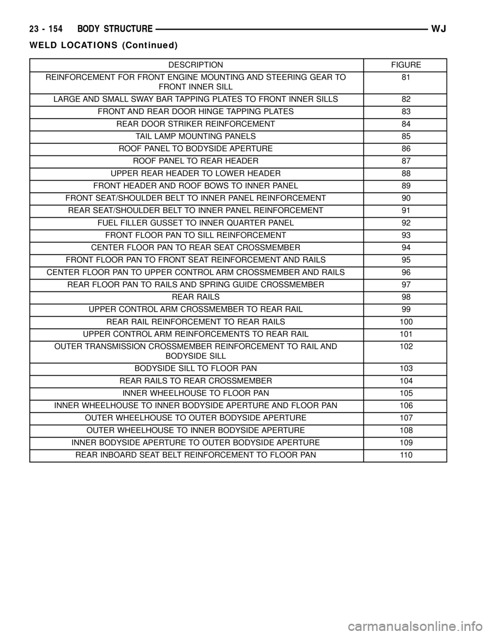
DESCRIPTION FIGURE
REINFORCEMENT FOR FRONT ENGINE MOUNTING AND STEERING GEAR TO
FRONT INNER SILL81
LARGE AND SMALL SWAY BAR TAPPING PLATES TO FRONT INNER SILLS 82
FRONT AND REAR DOOR HINGE TAPPING PLATES 83
REAR DOOR STRIKER REINFORCEMENT 84
TAIL LAMP MOUNTING PANELS 85
ROOF PANEL TO BODYSIDE APERTURE 86
ROOF PANEL TO REAR HEADER 87
UPPER REAR HEADER TO LOWER HEADER 88
FRONT HEADER AND ROOF BOWS TO INNER PANEL 89
FRONT SEAT/SHOULDER BELT TO INNER PANEL REINFORCEMENT 90
REAR SEAT/SHOULDER BELT TO INNER PANEL REINFORCEMENT 91
FUEL FILLER GUSSET TO INNER QUARTER PANEL 92
FRONT FLOOR PAN TO SILL REINFORCEMENT 93
CENTER FLOOR PAN TO REAR SEAT CROSSMEMBER 94
FRONT FLOOR PAN TO FRONT SEAT REINFORCEMENT AND RAILS 95
CENTER FLOOR PAN TO UPPER CONTROL ARM CROSSMEMBER AND RAILS 96
REAR FLOOR PAN TO RAILS AND SPRING GUIDE CROSSMEMBER 97
REAR RAILS 98
UPPER CONTROL ARM CROSSMEMBER TO REAR RAIL 99
REAR RAIL REINFORCEMENT TO REAR RAILS 100
UPPER CONTROL ARM REINFORCEMENTS TO REAR RAIL 101
OUTER TRANSMISSION CROSSMEMBER REINFORCEMENT TO RAIL AND
BODYSIDE SILL102
BODYSIDE SILL TO FLOOR PAN 103
REAR RAILS TO REAR CROSSMEMBER 104
INNER WHEELHOUSE TO FLOOR PAN 105
INNER WHEELHOUSE TO INNER BODYSIDE APERTURE AND FLOOR PAN 106
OUTER WHEELHOUSE TO OUTER BODYSIDE APERTURE 107
OUTER WHEELHOUSE TO INNER BODYSIDE APERTURE 108
INNER BODYSIDE APERTURE TO OUTER BODYSIDE APERTURE 109
REAR INBOARD SEAT BELT REINFORCEMENT TO FLOOR PAN 110
23 - 154 BODY STRUCTUREWJ
WELD LOCATIONS (Continued)
Page 2048 of 2199

Fig. 75 INNER TRACK BAR, LOWER CONTROL ARM AND TRANSMISSION CROSSMEMBER
BRACKETS TO FRONT SILLS
WJBODY STRUCTURE 23 - 175
WELD LOCATIONS (Continued)
Page 2050 of 2199

Fig. 77 UPPER SILLS AND UPPER CONTROL ARM REINFORCEMENT AND BRACKETS TO FRONT SILLS
WJBODY STRUCTURE 23 - 177
WELD LOCATIONS (Continued)
Page 2067 of 2199

Fig. 96 CENTER FLOOR PAN TO UPPER CONTROL ARM CROSSMEMBER AND RAILS
23 - 194 BODY STRUCTUREWJ
WELD LOCATIONS (Continued)
Page 2069 of 2199

Fig. 98 REAR RAILS
Fig. 99 UPPER CONTROL ARM CROSSMEMBER TO REAR RAIL
23 - 196 BODY STRUCTUREWJ
WELD LOCATIONS (Continued)