driver door module JEEP GRAND CHEROKEE 2002 WJ / 2.G Manual Online
[x] Cancel search | Manufacturer: JEEP, Model Year: 2002, Model line: GRAND CHEROKEE, Model: JEEP GRAND CHEROKEE 2002 WJ / 2.GPages: 2199, PDF Size: 76.01 MB
Page 1185 of 2199

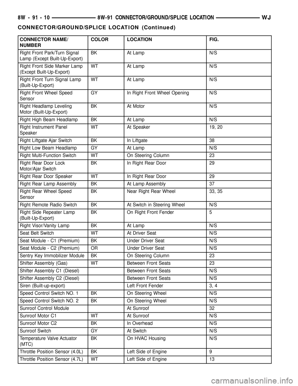
CONNECTOR NAME/
NUMBERCOLOR LOCATION FIG.
Right Front Park/Turn Signal
Lamp (Except Built-Up-Export)BK At Lamp N/S
Right Front Side Marker Lamp
(Except Built-Up-Export)WT At Lamp N/S
Right Front Turn Signal Lamp
(Built-Up-Export)WT At Lamp N/S
Right Front Wheel Speed
SensorGY In Right Front Wheel Opening N/S
Right Headlamp Leveling
Motor (Built-Up-Export)BK At Motor N/S
Right High Beam Headlamp BK At Lamp N/S
Right Instrument Panel
SpeakerWT At Speaker 19, 20
Right Liftgate Ajar Switch BK In Liftgate 38
Right Low Beam Headlamp GY At Lamp N/S
Right Multi-Function Switch WT On Steering Column 23
Right Rear Door Lock
Motor/Ajar SwitchBK In Right Rear Door 29
Right Rear Door Speaker WT In Right Rear Door 29
Right Rear Lamp Assembly BK At Lamp Assembly 37
Right Rear Wheel Speed
SensorBK Near Right Rear Wheel 33, 35
Right Remote Radio Switch BK At Switch in Steering Wheel N/S
Right Side Repeater Lamp
(Built-Up-Export)BK On Right Front Fender 5
Right Visor/Vanity Lamp BK At Lamp N/S
Seat Belt Switch WT At Driver Seat N/S
Seat Module - C1 (Premium) BK Under Driver Seat N/S
Seat Module - C2 (Premium) OR Under Driver Seat N/S
Sentry Key Immobilizer Module BK On Steering Column 23
Shifter Assembly (Gas) WT Between Front Seats 23
Shifter Assembly C1 (Diesel) Between Front Seats N/S
Shifter Assembly C2 (Diesel) Between Front Seats N/S
Siren (Built-up-export) Left Front Fender 3, 4
Speed Control Switch NO. 1 BK On Steering Wheel N/S
Speed Control Switch NO. 2 BK On Steering Wheel N/S
Sunroof Control Module At Sunroof 32
Sunroof Motor C1 WT At Sunroof N/S
Sunroof Motor C2 BK In Overhead N/S
Sunroof Switch GY At Switch N/S
Temperature Valve Actuator
(MTC)BK On HVAC Housing N/S
Throttle Position Sensor (4.0L) BK Left Side of Engine 9
Throttle Position Sensor (4.7L) WT Left Side of Engine 13
8W - 91 - 10 8W-91 CONNECTOR/GROUND/SPLICE LOCATIONWJ
CONNECTOR/GROUND/SPLICE LOCATION (Continued)
Page 1191 of 2199

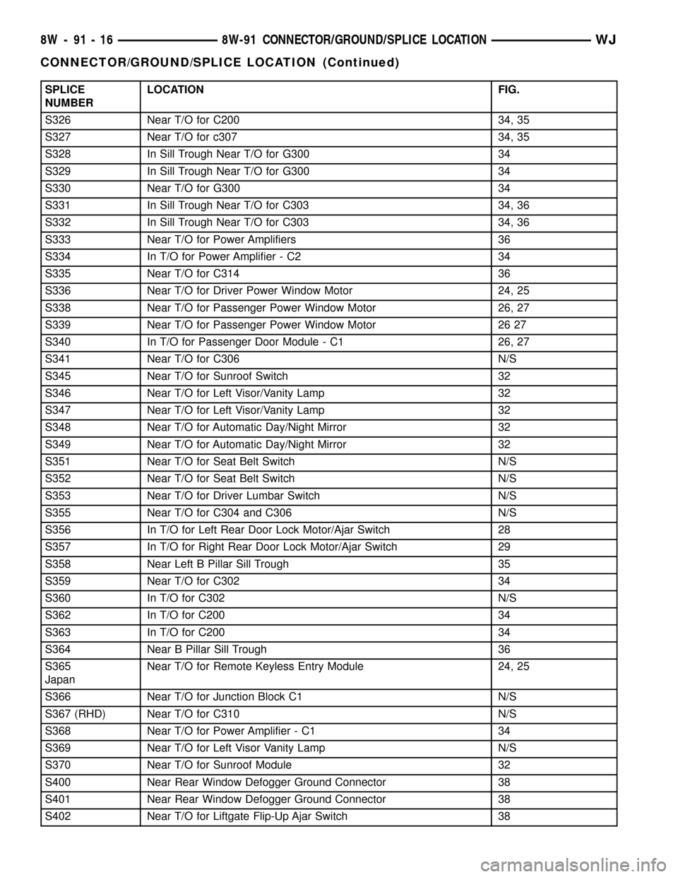
SPLICE
NUMBERLOCATION FIG.
S326 Near T/O for C200 34, 35
S327 Near T/O for c307 34, 35
S328 In Sill Trough Near T/O for G300 34
S329 In Sill Trough Near T/O for G300 34
S330 Near T/O for G300 34
S331 In Sill Trough Near T/O for C303 34, 36
S332 In Sill Trough Near T/O for C303 34, 36
S333 Near T/O for Power Amplifiers 36
S334 In T/O for Power Amplifier - C2 34
S335 Near T/O for C314 36
S336 Near T/O for Driver Power Window Motor 24, 25
S338 Near T/O for Passenger Power Window Motor 26, 27
S339 Near T/O for Passenger Power Window Motor 26 27
S340 In T/O for Passenger Door Module - C1 26, 27
S341 Near T/O for C306 N/S
S345 Near T/O for Sunroof Switch 32
S346 Near T/O for Left Visor/Vanity Lamp 32
S347 Near T/O for Left Visor/Vanity Lamp 32
S348 Near T/O for Automatic Day/Night Mirror 32
S349 Near T/O for Automatic Day/Night Mirror 32
S351 Near T/O for Seat Belt Switch N/S
S352 Near T/O for Seat Belt Switch N/S
S353 Near T/O for Driver Lumbar Switch N/S
S355 Near T/O for C304 and C306 N/S
S356 In T/O for Left Rear Door Lock Motor/Ajar Switch 28
S357 In T/O for Right Rear Door Lock Motor/Ajar Switch 29
S358 Near Left B Pillar Sill Trough 35
S359 Near T/O for C302 34
S360 In T/O for C302 N/S
S362 In T/O for C200 34
S363 In T/O for C200 34
S364 Near B Pillar Sill Trough 36
S365
JapanNear T/O for Remote Keyless Entry Module 24, 25
S366 Near T/O for Junction Block C1 N/S
S367 (RHD) Near T/O for C310 N/S
S368 Near T/O for Power Amplifier - C1 34
S369 Near T/O for Left Visor Vanity Lamp N/S
S370 Near T/O for Sunroof Module 32
S400 Near Rear Window Defogger Ground Connector 38
S401 Near Rear Window Defogger Ground Connector 38
S402 Near T/O for Liftgate Flip-Up Ajar Switch 38
8W - 91 - 16 8W-91 CONNECTOR/GROUND/SPLICE LOCATIONWJ
CONNECTOR/GROUND/SPLICE LOCATION (Continued)
Page 1916 of 2199

INSTALLATION
WARNING: ON VEHICLES EQUIPPED WITH AIR-
BAGS, DISABLE THE AIRBAG SYSTEM BEFORE
ATTEMPTING ANY STEERING WHEEL, STEERING
COLUMN, OR INSTRUMENT PANEL COMPONENT
DIAGNOSIS OR SERVICE. DISCONNECT AND ISO-
LATE THE BATTERY NEGATIVE (GROUND) CABLE,
THEN WAIT TWO MINUTES FOR THE AIRBAG SYS-
TEM CAPACITOR TO DISCHARGE BEFORE PER-
FORMING FURTHER DIAGNOSIS OR SERVICE. THIS
IS THE ONLY SURE WAY TO DISABLE THE AIRBAG
SYSTEM. FAILURE TO TAKE THE PROPER PRE-
CAUTIONS COULD RESULT IN ACCIDENTAL AIR-
BAG DEPLOYMENT AND POSSIBLE PERSONAL
INJURY.
(1) Prior to installing the instrument panel into
the vehicle, loosen the three nuts that secure the
instrument panel intermediate bracket and the accel-
erator pedal assembly to the studs on the dash panel
(Fig. 8).
(2) With the aid of an assistant, load the instru-
ment panel assembly through the driver side front
door of the vehicle and hang it on the studs on the
dash panel near the windshield fence line (Fig. 1).
(3) Be certain that the molded plastic hook forma-
tions on the instrument panel structural duct are
inserted into and seated in the guide holes at each
cowl side inner panel.
(4) Loosely install the two screws that secure each
end of the instrument panel to the cowl side inner
panels.
(5) Install and tighten the two screws that secure
the passenger side instrument panel structural duct
to the heater and air conditioner housing (Fig. 13).
Tighten the screws to 11.8 N´m (105 in. lbs.).
(6) Install and tighten the one screw that secures
the instrument panel steering column support
bracket to the driver side end of the heater and air
conditioner housing (Fig. 7). Tighten the screw to
11.8 N´m (105 in. lbs.).
(7) Tighten the two screws that secure each end of
the instrument panel to the cowl side inner panels
(Fig. 10) and (Fig. 14). Tighten the screws to 11.8
N´m (105 in. lbs.).
(8) Install and tighten the one screw that secures
the instrument panel steering column support
bracket to the intermediate bracket on the driver
side dash panel (Fig. 8). Tighten the screw to 11.3
N´m (100 in. lbs.).
(9) Tighten the three nuts that secure the instru-
ment panel intermediate bracket and the accelerator
pedal assembly to the studs on the dash panel.
Tighten the nuts to 11.3 N´m (100 in. lbs.).(10) Install and tighten the four nuts that secure
the instrument panel to the studs on the dash panel
near the windshield fence line. Tighten the nuts to
11.8 N´m (105 in. lbs.).
(11) Install and tighten the nut that secures the
instrument panel steering column support bracket to
the stud on the driver side cowl plenum panel (Fig.
9). Tighten the nut to 28.2 N´m (250 in. lbs.).
(12) Reinstall the instrument panel to center floor
tunnel bracket onto the instrument panel and the
floor panel transmission tunnel. (Refer to 23 - BODY/
INSTRUMENT PANEL/IP CENTER FLOOR TUN-
NEL BRACKET - INSTALLATION).
(13) Reconnect the two instrument panel wire har-
ness connectors to the two heater and air conditioner
housing connectors located near the blower motor on
the passenger side end of the housing (Fig. 12).
(14) Reconnect the two halves of the radio antenna
coaxial cable connector near the right cowl side inner
panel under the end of the instrument panel.
(15) Reconnect the instrument panel wire harness
connector to the lower cavity of the inline connector
on the passenger side cowl side inner panel and
tighten the connector screw (Fig. 11). Tighten the
screw to 4 N´m (36 in. lbs.).
(16) Reinstall the lower right center bezel onto the
instrument panel. (Refer to 23 - BODY/INSTRU-
MENT PANEL/IP LOWER RIGHT CENTER BEZEL
- INSTALLATION).
(17) Reinstall the end cap onto the instrument
panel. (Refer to 23 - BODY/INSTRUMENT PANEL/
INSTRUMENT PANEL END CAP - INSTALLA-
TION).
(18) If the vehicle is equipped with the manual
heating and air conditioning system, reconnect the
vacuum harness connector located near the driver
side of the floor panel transmission tunnel behind
the driver side floor duct.
(19) Position the driver side floor duct to the
heater and air conditioner housing near the driver
side of the floor panel transmission tunnel (Fig. 7).
(20) Install and tighten the one screw that secures
the driver side floor duct to the heater and air con-
ditioner housing near the driver side of the floor
panel transmission tunnel. Tighten the screw to 2.2
N´m (20 in. lbs.).
(21) Route the instrument panel wire harness to
the floor panel transmission tunnel and engage the
retainers that secure the harness to the mounting
brackets on the tunnel (Fig. 6).
(22) Install the instrument panel wire harness
ground eyelets to the studs on the floor panel trans-
mission tunnel in front of and behind the airbag con-
trol module and secure the eyelets with nuts. Tighten
the nuts to 7.3 N´m (65 in. lbs.).
WJINSTRUMENT PANEL SYSTEM 23 - 43
INSTRUMENT PANEL SYSTEM (Continued)
Page 2097 of 2199

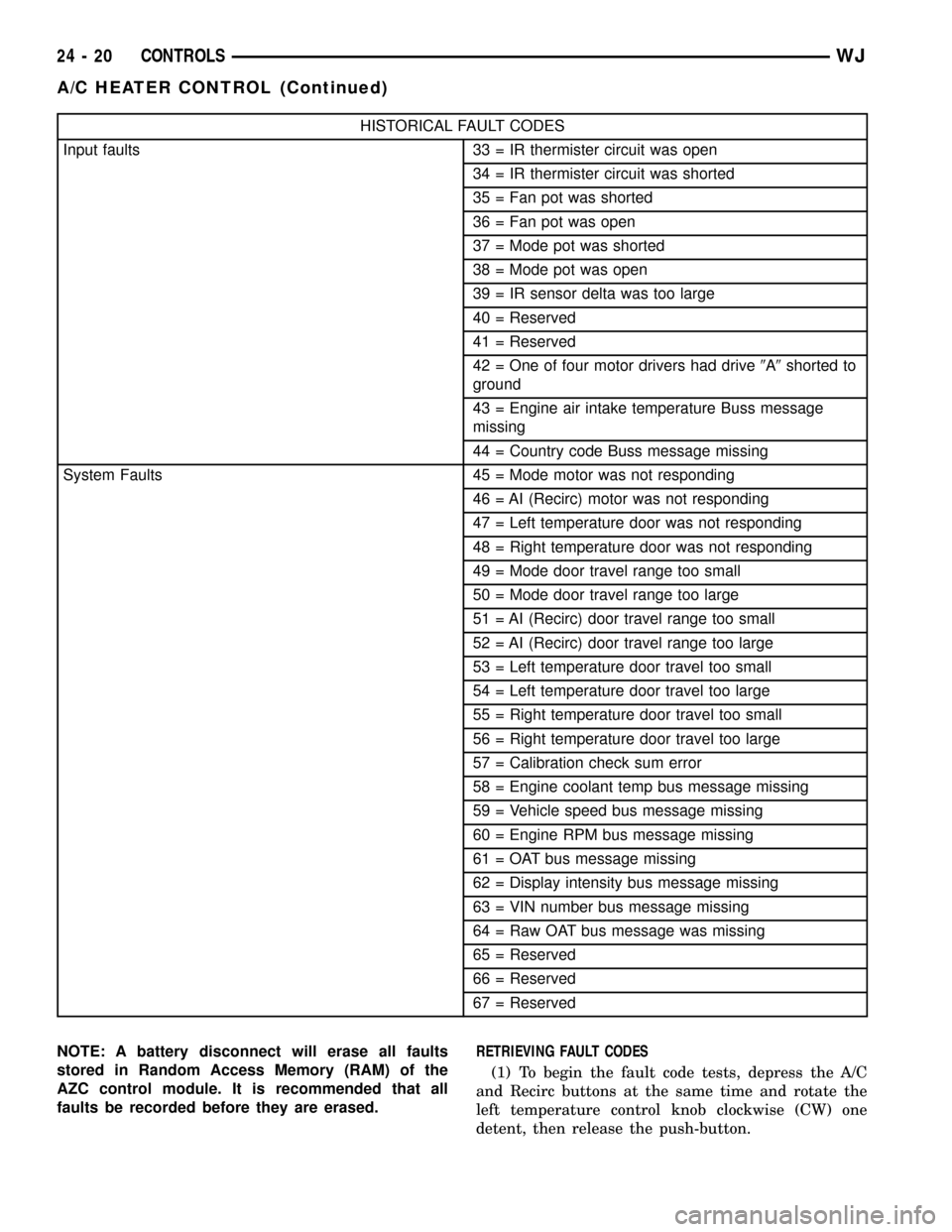
HISTORICAL FAULT CODES
Input faults 33 = IR thermister circuit was open
34 = IR thermister circuit was shorted
35 = Fan pot was shorted
36 = Fan pot was open
37 = Mode pot was shorted
38 = Mode pot was open
39 = IR sensor delta was too large
40 = Reserved
41 = Reserved
42 = One of four motor drivers had drive9A9shorted to
ground
43 = Engine air intake temperature Buss message
missing
44 = Country code Buss message missing
System Faults 45 = Mode motor was not responding
46 = AI (Recirc) motor was not responding
47 = Left temperature door was not responding
48 = Right temperature door was not responding
49 = Mode door travel range too small
50 = Mode door travel range too large
51 = AI (Recirc) door travel range too small
52 = AI (Recirc) door travel range too large
53 = Left temperature door travel too small
54 = Left temperature door travel too large
55 = Right temperature door travel too small
56 = Right temperature door travel too large
57 = Calibration check sum error
58 = Engine coolant temp bus message missing
59 = Vehicle speed bus message missing
60 = Engine RPM bus message missing
61 = OAT bus message missing
62 = Display intensity bus message missing
63 = VIN number bus message missing
64 = Raw OAT bus message was missing
65 = Reserved
66 = Reserved
67 = Reserved
NOTE: A battery disconnect will erase all faults
stored in Random Access Memory (RAM) of the
AZC control module. It is recommended that all
faults be recorded before they are erased.RETRIEVING FAULT CODES
(1) To begin the fault code tests, depress the A/C
and Recirc buttons at the same time and rotate the
left temperature control knob clockwise (CW) one
detent, then release the push-button.
24 - 20 CONTROLSWJ
A/C HEATER CONTROL (Continued)
Page 2122 of 2199

NOTE: The blend door sub-assembly is attached to
the housing with 2 screws, and may be removed for
service (Fig. 19).
ASSEMBLY
(1) Place the top half of the HVAC housing on the
bottom half. Be certain that each of the door pivot
pins align with the pivot holes in the HVAC housing.
(2) Install the 10 screws that secure the two hous-
ing halves to each other. Tighten the HVAC housing
screws to 2.2 N´m (20 in. lbs.).
(3) Attach the wire harness electrical connector(s)
to the mounts on the lower case at the blower motor
end of the unit.
(4) Install the 5 clips that secure the two housing
halves to each other. Check doors for binding after
replacement, and after assembly of housing.
(5) Install the screw with plastic washer holding
the lever assembly to the upper case section.
(6) Install the mode door actuator on the left side
of the housing.
INSTALLATION
WARNING: REVIEW THE WARNINGS AND CAU-
TIONS IN PLUMBING BEFORE PERFORMING THE
FOLLOWING OPERATION. (Refer to 24 - HEATING &
AIR CONDITIONING/PLUMBING - WARNING) (Refer
to 24 - HEATING & AIR CONDITIONING/PLUMBING -
CAUTION)Any kinks or sharp bends in the refrigerant plumb-
ing will reduce the capacity of the entire air condi-
tioning system. Kinks and sharp bends reduce the
flow of refrigerant in the system. A good rule for the
flexible hose refrigerant lines is to keep the radius of
all bends at least ten times the diameter of the hose.
In addition, the flexible hose refrigerant lines should
be routed so they are at least 80 millimeters (3
inches) from the exhaust manifold.
High pressures are produced in the refrigerant sys-
tem when the air conditioning compressor is operat-
ing. Extreme care must be exercised to make sure
that each of the refrigerant system connections is
pressure-tight and leak free. It is a good practice to
inspect all flexible hose refrigerant lines at least once
a year to make sure they are in good condition and
properly routed.
(1) Position the HVAC housing to the dash panel.
Be certain that the evaporator condensate drain tube
and the housing mounting studs are inserted into
their correct mounting holes.
(2) Install the HVAC housing mounting nuts to the
studs on the passenger compartment side of the dash
panel. Tighten the nuts to 4.5 N´m (40 in. lbs.).
(3) Connect the HVAC housing wire harness con-
nectors.
(4) Reinstall the rear floor heat ducts to the center
floor heat duct outlets.
(5) Install and tighten the nuts onto the HVAC
housing mounting studs on the engine compartment
side of the dash panel. Tighten the nuts to 7 N´m (60
in. lbs.).
(6) Reinstall the PCM to the passenger side dash
panel in the engine compartment. Refer to Electronic
Control Modules for the procedures.
(7) Reinstall the coolant reserve/overflow bottle to
the passenger side inner fender shield. Refer to Cool-
ing for the procedures.
(8) If the vehicle is equipped with the manual tem-
perature control system, connect the HVAC system
vacuum supply line connector to the tee fitting near
the heater core tubes.
(9) Unclamp/unplug the heater core hoses and
tubes. Connect the heater hoses to the heater core
tubes and fill the engine cooling system. Refer to
Cooling for the procedures.
(10) Unplug or remove the tape from the suction
line and the evaporator outlet tube fittings. Connect
the suction line to the evaporator outlet tube.
Tighten retaining nut to 28 N´m (250 in. lbs.).
(11) Unplug or remove the tape from the liquid
line and the evaporator inlet tube fittings. Connect
the liquid line to the evaporator inlet tube. Tighten
retaining nut to 28 N´m (250 in. lbs.).
(12) Evacuate the refrigerant system. (Refer to 24
- HEATING & AIR CONDITIONING/PLUMBING -
Fig. 19 BLEND DOOR SUB-ASSEMBLY (AZC)
1 - PASSENGER SIDE BLEND DOOR
2 - BLEND DOOR SUB-ASSEMBLY
3 - DOOR PIVOT SHAFT BUSHING
4 - DOOR SHAFT LEVER
5 - DRIVER SIDE BLEND DOOR
WJDISTRIBUTION 24 - 45
HVAC HOUSING (Continued)