Dash bolts JEEP GRAND CHEROKEE 2002 WJ / 2.G Workshop Manual
[x] Cancel search | Manufacturer: JEEP, Model Year: 2002, Model line: GRAND CHEROKEE, Model: JEEP GRAND CHEROKEE 2002 WJ / 2.GPages: 2199, PDF Size: 76.01 MB
Page 181 of 2199

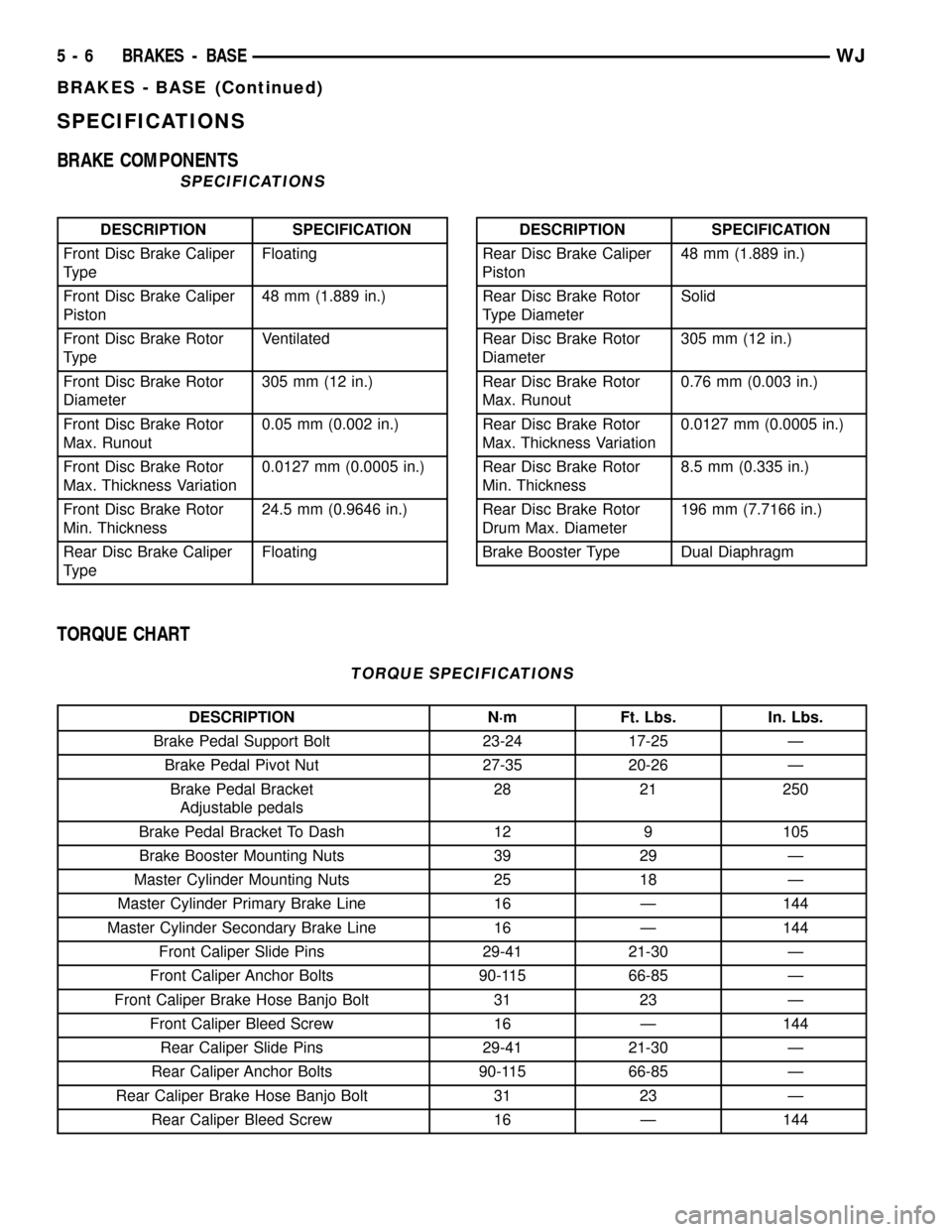
SPECIFICATIONS
BRAKE COMPONENTS
SPECIFICATIONS
DESCRIPTION SPECIFICATION
Front Disc Brake Caliper
TypeFloating
Front Disc Brake Caliper
Piston48 mm (1.889 in.)
Front Disc Brake Rotor
TypeVentilated
Front Disc Brake Rotor
Diameter305 mm (12 in.)
Front Disc Brake Rotor
Max. Runout0.05 mm (0.002 in.)
Front Disc Brake Rotor
Max. Thickness Variation0.0127 mm (0.0005 in.)
Front Disc Brake Rotor
Min. Thickness24.5 mm (0.9646 in.)
Rear Disc Brake Caliper
TypeFloatingDESCRIPTION SPECIFICATION
Rear Disc Brake Caliper
Piston48 mm (1.889 in.)
Rear Disc Brake Rotor
Type DiameterSolid
Rear Disc Brake Rotor
Diameter305 mm (12 in.)
Rear Disc Brake Rotor
Max. Runout0.76 mm (0.003 in.)
Rear Disc Brake Rotor
Max. Thickness Variation0.0127 mm (0.0005 in.)
Rear Disc Brake Rotor
Min. Thickness8.5 mm (0.335 in.)
Rear Disc Brake Rotor
Drum Max. Diameter196 mm (7.7166 in.)
Brake Booster Type Dual Diaphragm
TORQUE CHART
TORQUE SPECIFICATIONS
DESCRIPTION N´m Ft. Lbs. In. Lbs.
Brake Pedal Support Bolt 23-24 17-25 Ð
Brake Pedal Pivot Nut 27-35 20-26 Ð
Brake Pedal Bracket
Adjustable pedals28 21 250
Brake Pedal Bracket To Dash 12 9 105
Brake Booster Mounting Nuts 39 29 Ð
Master Cylinder Mounting Nuts 25 18 Ð
Master Cylinder Primary Brake Line 16 Ð 144
Master Cylinder Secondary Brake Line 16 Ð 144
Front Caliper Slide Pins 29-41 21-30 Ð
Front Caliper Anchor Bolts 90-115 66-85 Ð
Front Caliper Brake Hose Banjo Bolt 31 23 Ð
Front Caliper Bleed Screw 16 Ð 144
Rear Caliper Slide Pins 29-41 21-30 Ð
Rear Caliper Anchor Bolts 90-115 66-85 Ð
Rear Caliper Brake Hose Banjo Bolt 31 23 Ð
Rear Caliper Bleed Screw 16 Ð 144
5 - 6 BRAKES - BASEWJ
BRAKES - BASE (Continued)
Page 209 of 2199

INSTALLATION
INSTALLATION - FRONT DISC BRAKE ROTOR
NOTE: If a new rotor is installed it must be match
mounted to the hub/bearing.
(1) Install rotor on hub studs in its original loca-
tion.
(2) Install the caliper anchor assembly on the
knuckle. Install anchor bolts and tighten to 90-115
N´m (66-85 ft. lbs.).
(3) Install wheel and tire assembly.
(4) Remove support and lower the vehicle.
(5) Pump brake pedal to seat caliper pistons and
brake shoes. Do not move vehicle until firm brake
pedal is obtained.
INSTALLATION - REAR DISC BRAKE ROTOR
(1) Install rotor on axle studs.
(2) Install the caliper anchor assembly.
(3) Install anchor bolts and tighten to 90-115 N´m
(66-85 ft. lbs.).
(4) Install wheel and tire assembly.
(5) Remove support and lower the vehicle.
(6) Pump brake pedal until caliper pistons and
brake shoes are seated.
PARKING BRAKE
OPERATION
The parking brakes operated by a automatic ten-
sioner mechanism built into the hand lever and cable
system. The front cable is connected to the hand
lever and the equalizer. The rear cables attached to
the equalizer and the parking brake shoe actuator.
A set of drum type brake shoes are used for park-
ing brakes. The shoes are mounted to the rear disc
brake adaptor. The parking brake drum is integrated
into the rear disc brake rotor.
Parking brake cable adjustment is controlled by an
automatic tensioner mechanism. The only adjust-
ment if necessary is to the park brake shoes if the
linings are worn.
DIAGNOSIS AND TESTING - PARKING BRAKE
NOTE: Parking brake adjustment is controlled by an
automatic cable tensioner and does not require
adjustment. The only adjustment that may be nec-
essary would be to the park brake shoes if they are
worn.
The parking brake switch is in circuit with the red
warning lamp in the dash. The switch will cause the
lamp to illuminate only when the parking brakes are
applied. If the lamp remains on after parking brake
release, the switch or wires are faulty.
If the red lamp comes on a fault has occurred in
the front or rear brake hydraulic system.
If the red warning lamp and yellow warning lamp
come on, the electronic brake distribution may be at
fault.
In most cases, the actual cause of an improperly
functioning parking brake (too loose/too tight/won't
hold), can be traced to a parking brake component.
NOTE: The leading cause of improper parking brake
operation, is excessive clearance between the park-
ing brake shoes and the shoe braking surface.
Excessive clearance is a result of lining and/or
drum wear, drum surface machined oversize.
Excessive parking brake lever travel (sometimes
described as a loose lever or too loose condition), is
the result of worn brake shoes, improper brake shoe
adjustment, or improperly assembled brake parts.
A too loose condition can also be caused by inoper-
ative or improperly assembled parking brake shoe
parts.
A condition where the parking brakes do not hold,
will most probably be due to a wheel brake compo-
nent.
Items to look for when diagnosing a parking brake
problem, are:
²Brake shoe wear
²Drum surface (in rear rotor) machined oversize
²Front cable not secured to lever
²Rear cable not attached to actuator
²Rear cable seized
²Parking brake lever not seated
²Parking brake lever bind
5 - 34 BRAKES - BASEWJ
ROTORS (Continued)
Page 1458 of 2199

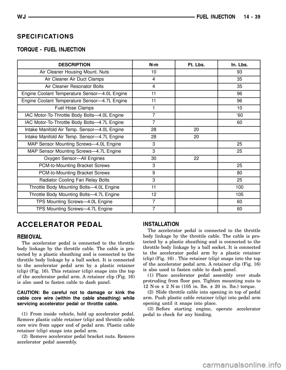
SPECIFICATIONS
TORQUE - FUEL INJECTION
DESCRIPTION N-m Ft. Lbs. In. Lbs.
Air Cleaner Housing Mount. Nuts 10 93
Air Cleaner Air Duct Clamps 4 35
Air Cleaner Resonator Bolts 4 35
Engine Coolant Temperature SensorÐ4.0L Engine 11 96
Engine Coolant Temperature SensorÐ4.7L Engine 11 96
Fuel Hose Clamps 1 10
IAC Motor-To-Throttle Body BoltsÐ4.0L Engine 7860
IAC Motor-To-Throttle Body BoltsÐ4.7L Engine 7 60
Intake Manifold Air Temp. SensorÐ4.0L Engine 28 20
Intake Manifold Air Temp. SensorÐ4.7L Engine 28 20
MAP Sensor Mounting ScrewsÐ4.0L Engine 3 25
MAP Sensor Mounting ScrewsÐ4.7L Engine 3 25
Oxygen SensorÐAll Engines 30 22
PCM-to-Mounting Bracket Screws 3 25
PCM-to-Mounting Bracket Screws 9 80
Radiator Cooling Fan Relay Bolts 3 25
Throttle Body Mounting BoltsÐ4.0L Engine 11 100
Throttle Body Mounting BoltsÐ4.7L Engine 12 105
TPS Mounting ScrewsÐ4.0L Engine 7 60
TPS Mounting ScrewsÐ4.7L Engine 7 60
ACCELERATOR PEDAL
REMOVAL
The accelerator pedal is connected to the throttle
body linkage by the throttle cable. The cable is pro-
tected by a plastic sheathing and is connected to the
throttle body linkage by a ball socket. It is connected
to the accelerator pedal arm by a plastic retainer
(clip) (Fig. 16). This retainer (clip) snaps into the top
of the accelerator pedal arm. A retainer clip (Fig. 16)
is also used to fasten cable to dash panel.
CAUTION: Be careful not to damage or kink the
cable core wire (within the cable sheathing) while
servicing accelerator pedal or throttle cable.
(1) From inside vehicle, hold up accelerator pedal.
Remove plastic cable retainer (clip) and throttle cable
core wire from upper end of pedal arm. Plastic cable
retainer (clip) snaps into pedal arm.
(2) Remove accelerator pedal bracket nuts. Remove
accelerator pedal assembly.
INSTALLATION
The accelerator pedal is connected to the throttle
body linkage by the throttle cable. The cable is pro-
tected by a plastic sheathing and is connected to the
throttle body linkage by a ball socket. It is connected
to the accelerator pedal arm by a plastic retainer
(clip) (Fig. 16) . This retainer (clip) snaps into the top
of the accelerator pedal arm. A retainer clip (Fig. 16)
is also used to fasten cable to dash panel.
(1) Place accelerator pedal assembly over studs
protruding from floor pan. Tighten mounting nuts to
12 N´m 2 N´m (105 in. lbs. 20 in. lbs.) torque.
(2) Slide throttle cable into opening in top of pedal
arm. Push plastic cable retainer (clip) into pedal arm
opening until it snaps into place.
(3) Before starting engine, operate accelerator
pedal to check for any binding.
WJFUEL INJECTION 14 - 39
Page 1464 of 2199

The PCM uses the IAC motor to control idle speed
(along with timing) and to reach a desired MAP dur-
ing decel (keep engine from stalling).
The IAC motor has 4 wires with 4 circuits. Two of
the wires are for 12 volts and ground to supply elec-
trical current to the motor windings to operate the
stepper motor in one direction. The other 2 wires are
also for 12 volts and ground to supply electrical cur-
rent to operate the stepper motor in the opposite
direction.
To make the IAC go in the opposite direction, the
PCM just reverses polarity on both windings. If only
1 wire is open, the IAC can only be moved 1 step
(increment) in either direction. To keep the IAC
motor in position when no movement is needed, the
PCM will energize both windings at the same time.
This locks the IAC motor in place.
In the IAC motor system, the PCM will count
every step that the motor is moved. This allows the
PCM to determine the motor pintle position. If the
memory is cleared, the PCM no longer knows the
position of the pintle. So at the first key ON, the
PCM drives the IAC motor closed, regardless of
where it was before. This zeros the counter. From
this point the PCM will back out the IAC motor and
keep track of its position again.
When engine rpm is above idle speed, the IAC is
used for the following:
²Off-idle dashpot (throttle blade will close quickly
but idle speed will not stop quickly)
²Deceleration air flow control
²A/C compressor load control (also opens the pas-
sage slightly before the compressor is engaged so
that the engine rpm does not dip down when the
compressor engages)
²Power steering load control
The PCM can control polarity of the circuit to con-
trol direction of the stepper motor.
IAC Stepper Motor Program:The PCM is also
equipped with a memory program that records the
number of steps the IAC stepper motor most recently
advanced to during a certain set of parameters. For
example: The PCM was attempting to maintain a
1000 rpm target during a cold start-up cycle. The last
recorded number of steps for that may have been
125. That value would be recorded in the memory
cell so that the next time the PCM recognizes the
identical conditions, the PCM recalls that 125 steps
were required to maintain the target. This program
allows for greater customer satisfaction due to
greater control of engine idle.
Another function of the memory program, which
occurs when the power steering switch (if equipped),
or the A/C request circuit, requires that the IAC step-
per motor control engine rpm, is the recording of the
last targeted steps into the memory cell. The PCMcan anticipate A/C compressor loads. This is accom-
plished by delaying compressor operation for approx-
imately 0.5 seconds until the PCM moves the IAC
stepper motor to the recorded steps that were loaded
into the memory cell. Using this program helps elim-
inate idle-quality changes as loads change. Finally,
the PCM incorporates a9No-Load9engine speed lim-
iter of approximately 1800 - 2000 rpm, when it rec-
ognizes that the TPS is indicating an idle signal and
IAC motor cannot maintain engine idle.
A (factory adjusted) set screw is used to mechani-
cally limit the position of the throttle body throttle
plate.Never attempt to adjust the engine idle
speed using this screw.All idle speed functions are
controlled by the IAC motor through the PCM.
REMOVAL
REMOVAL - 4.0L
The IAC motor is located on the throttle body.
(1) Remove air duct and air resonator box at throt-
tle body.
(2) Disconnect electrical connector from IAC motor
(Fig. 40).
(3) Remove two mounting bolts (screws) (Fig. 26).
(4) Remove IAC motor from throttle body.
REMOVAL - 4.7L
(1) Remove air duct and air resonator box at throt-
tle body.
(2) Disconnect electrical connector from IAC motor
(Fig. 36).
(3) Remove two mounting bolts (screws) (Fig. 42).
(4) Remove IAC motor from throttle body.
Fig. 26 Mounting Bolts (Screws)ÐIAC
1 - IDLE AIR CONTROL MOTOR
2 - MOUNTING SCREWS
WJFUEL INJECTION 14 - 45
IDLE AIR CONTROL MOTOR (Continued)
Page 1473 of 2199

INSTALLATION - 4.7L
(1) Clean throttle body-to-intake manifold o-ring.
(2) Clean mating surfaces of throttle body and
intake manifold.
(3) Install throttle body to intake manifold by posi-
tioning throttle body to manifold alignment pins.
(4) Install three mounting bolts. Tighten bolts to
12 N´m (105 in. lbs.) torque.
(5) Install control cables.
(6) Install vacuum line to throttle body.
(7) Install electrical connectors.
(8) Install air duct/air box at throttle body.
THROTTLE CONTROL CABLE
REMOVAL
REMOVAL - 4.0L
CAUTION: Be careful not to damage or kink the
cable core wire (within the cable sheathing) while
servicing accelerator pedal or throttle cable.
(1) From inside vehicle, hold up accelerator pedal.
Remove plastic cable retainer (clip) and throttle cable
core wire from upper end of pedal arm (Fig. 16).
Plastic cable retainer (clip) snaps into pedal arm.
(2) Remove cable core wire at pedal arm.
(3) From inside vehicle, remove clip holding cable
to dashpanel (Fig. 16).
(4) Remove cable housing from dash panel and
pull into engine compartment.
(5) Remove (unsnap) cable from routing clips on
engine valve cover.
(6) Remove cable connector at throttle body
bellcrank ball by unsnapping rearward (Fig. 37).
(7) Remove throttle cable from bracket by com-
pressing release tabs (Fig. 37) and pushing cable
through hole in bracket.
(8) Remove throttle cable from vehicle.
Fig. 35 Throttle Body and Sensor LocationsÐ4.0L
Engine
1 - MOUNTING BOLTS (4)
2 - THROTTLE BODY
3 - IAC MOTOR
4 - ELEC. CONN.
5 - TPS
6 - MAP SENSOR
7 - ELEC. CONN.
8 - IAT SENSOR
9 - ELEC. CONN.
Fig. 36 Throttle Body, Sensors and Electrical
ConnectorsÐ4.7L V-8 Engine
1 - MOUNTING BOLTS (3)
2 - THROTTLE BODY
3 - IAT SENSOR CONNECTOR
4 - IAC MOTOR CONNECTOR
5 - TPS CONNECTOR
14 - 54 FUEL INJECTIONWJ
THROTTLE BODY (Continued)
Page 1479 of 2199

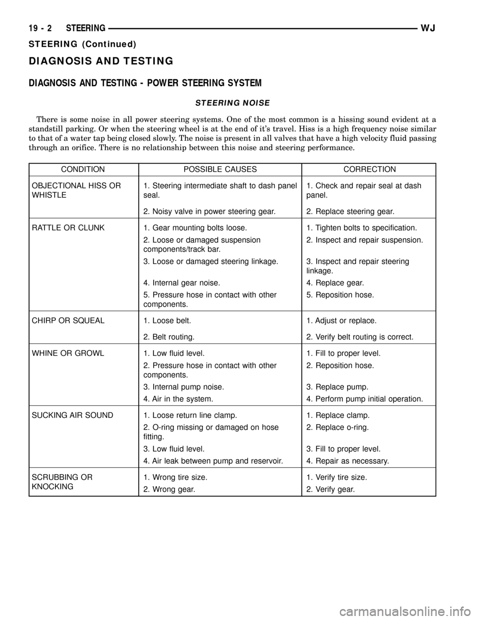
DIAGNOSIS AND TESTING
DIAGNOSIS AND TESTING - POWER STEERING SYSTEM
STEERING NOISE
There is some noise in all power steering systems. One of the most common is a hissing sound evident at a
standstill parking. Or when the steering wheel is at the end of it's travel. Hiss is a high frequency noise similar
to that of a water tap being closed slowly. The noise is present in all valves that have a high velocity fluid passing
through an orifice. There is no relationship between this noise and steering performance.
CONDITION POSSIBLE CAUSES CORRECTION
OBJECTIONAL HISS OR
WHISTLE1. Steering intermediate shaft to dash panel
seal.1. Check and repair seal at dash
panel.
2. Noisy valve in power steering gear. 2. Replace steering gear.
RATTLE OR CLUNK 1. Gear mounting bolts loose. 1. Tighten bolts to specification.
2. Loose or damaged suspension
components/track bar.2. Inspect and repair suspension.
3. Loose or damaged steering linkage. 3. Inspect and repair steering
linkage.
4. Internal gear noise. 4. Replace gear.
5. Pressure hose in contact with other
components.5. Reposition hose.
CHIRP OR SQUEAL 1. Loose belt. 1. Adjust or replace.
2. Belt routing. 2. Verify belt routing is correct.
WHINE OR GROWL 1. Low fluid level. 1. Fill to proper level.
2. Pressure hose in contact with other
components.2. Reposition hose.
3. Internal pump noise. 3. Replace pump.
4. Air in the system. 4. Perform pump initial operation.
SUCKING AIR SOUND 1. Loose return line clamp. 1. Replace clamp.
2. O-ring missing or damaged on hose
fitting.2. Replace o-ring.
3. Low fluid level. 3. Fill to proper level.
4. Air leak between pump and reservoir. 4. Repair as necessary.
SCRUBBING OR
KNOCKING1. Wrong tire size. 1. Verify tire size.
2. Wrong gear. 2. Verify gear.
19 - 2 STEERINGWJ
STEERING (Continued)
Page 2085 of 2199

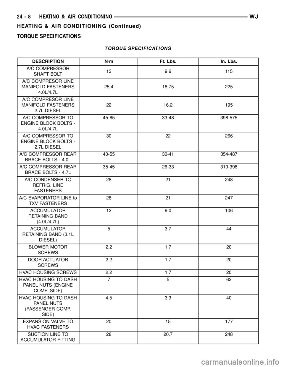
TORQUE SPECIFICATIONS
TORQUE SPECIFICATIONS
DESCRIPTION N´m Ft. Lbs. In. Lbs.
A/C COMPRESSOR
SHAFT BOLT13 9.6 115
A/C COMPRESOR LINE
MANIFOLD FASTENERS
4.0L/4.7L25.4 18.75 225
A/C COMPRESOR LINE
MANIFOLD FASTENERS
2.7L DIESEL22 16.2 195
A/C COMPRESSOR TO
ENGINE BLOCK BOLTS -
4.0L/4.7L45-65 33-48 398-575
A/C COMPRESSOR TO
ENGINE BLOCK BOLTS -
2.7L DIESEL30 22 266
A/C COMPRESSOR REAR
BRACE BOLTS - 4.0L40-55 30-41 354-487
A/C COMPRESSOR REAR
BRACE BOLTS - 4.7L35-45 26-33 310-398
A/C CONDENSER TO
REFRIG. LINE
FASTENERS28 21 248
A/C EVAPORATOR LINE to
TXV FASTENERS28 21 247
ACCUMULATOR
RETAINING BAND
(4.0L/4.7L)12 9.0 106
ACCUMULATOR
RETAINING BAND (3.1L
DIESEL)5 3.7 44
BLOWER MOTOR
SCREWS2.2 1.7 20
DOOR ACTUATOR
SCREWS2.2 1.7 20
HVAC HOUSING SCREWS 2.2 1.7 20
HVAC HOUSING TO DASH
PANEL NUTS (ENGINE
COMP. SIDE)75 62
HVAC HOUSING TO DASH
PANEL NUTS
(PASSENGER COMP.
SIDE)4.5 3.3 40
EXPANSION VALVE TO
HVAC FASTENERS20 15 177
SUCTION LINE TO
ACCUMULATOR FITTING28 20.7 248
24 - 8 HEATING & AIR CONDITIONINGWJ
HEATING & AIR CONDITIONING (Continued)