Rear differential JEEP GRAND CHEROKEE 2002 WJ / 2.G Workshop Manual
[x] Cancel search | Manufacturer: JEEP, Model Year: 2002, Model line: GRAND CHEROKEE, Model: JEEP GRAND CHEROKEE 2002 WJ / 2.GPages: 2199, PDF Size: 76.01 MB
Page 17 of 2199
DESCRIPTION - ENGINE OIL - DIESEL
ENGINES
Use only Diesel Engine Oil meeting standardMIL-
2104Cor API ClassificationCD or higherorCCML
D4, D5.
SAE VISCOSITY GRADE
CAUTION: Low viscosity oils must have the proper
API quality or the CCMC G5 designation.
To assure of properly formulated engine oils, it is
recommended that SAE Grade 10W-40 engine oils
that meet Chrysler material standard MS-6395, be
used. European Grade 10W-40 oils are also accept-
able.
Oils of the SAE 5W-40 or 8W-80 grade number are
preferred when minimum temperatures consistently
fall below -12ÉC.
OPERATION - AUTOMATIC TRANSMISSION
FLUID
The automatic transmission fluid is selected based
upon several qualities. The fluid must provide a high
level of protection for the internal components by
providing a lubricating film between adjacent metal
components. The fluid must also be thermally stable
so that it can maintain a consistent viscosity through
a large temperature range. If the viscosity stays con-
stant through the temperature range of operation,
transmission operation and shift feel will remain con-
sistent. Transmission fluid must also be a good con-
ductor of heat. The fluid must absorb heat from the
internal transmission components and transfer that
heat to the transmission case.
FLUID FILL/CHECK
LOCATIONS
INSPECTION - FLUID FILL/CHECK LOCATIONS
The fluid fill/check locations and lubrication points
are located in each applicable group.
MAINTENANCE SCHEDULES
DESCRIPTION
9Maintenance Schedule Information not included in
this section, is located in the appropriate Owner's
Manual.9
LIFT POINTS
STANDARD PROCEDURE - HOISTING AND
JACKING RECOMMENDATIONS
FLOOR JACK
When properly positioned, a floor jack can be used
to lift a WJ vehicle (Fig. 7). Support the vehicle in
the raised position with jack stands at the front and
rear ends of the frame rails.
CAUTION: Do not attempt to lift a vehicle with a
floor jack positioned under:
²An axle tube.
²Aluminum differential.
²A body side sill.
²A steering linkage component.
²A drive shaft.
²The engine or transmission oil pan.
²The fuel tank.
²A front suspension arm.
HOIST
A vehicle can be lifted with:
²A single-post, frame-contact hoist.
²A twin-post, chassis hoist.
²A ramp-type, drive-on hoist.
NOTE: When a frame-contact type hoist is used,
verify that the lifting pads are positioned properly
(Fig. 7).
WARNING: THE HOISTING AND JACK LIFTING
POINTS PROVIDED ARE FOR A COMPLETE VEHI-
CLE. WHEN A CHASSIS OR DRIVETRAIN COMPO-
NENT IS REMOVED FROM A VEHICLE, THE
CENTER OF GRAVITY IS ALTERED MAKING SOME
HOISTING CONDITIONS UNSTABLE. PROPERLY
SUPPORT OR SECURE VEHICLE TO HOISTING
DEVICE WHEN THESE CONDITIONS EXIST.
0 - 6 LUBRICATION & MAINTENANCEWJ
FLUID TYPES (Continued)
Page 42 of 2199
STABILIZER BAR
DESCRIPTION
The stabilizer bar extends across the back side of
the rear axle. Links are connected between the bar
and frame rail brackets. The stabilizer bar and links
are isolated by rubber bushings.
OPERATION
The stabilizer bar is used to control vehicle body
roll, during turns. The bar helps control the vehicle
body in relationship to the suspension.
REMOVAL
(1) Raise and support the vehicle.
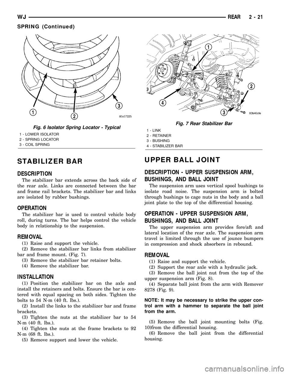
(2) Remove the stabilizer bar links from stabilizer
bar and frame mount. (Fig. 7).
(3) Remove the stabilizer bar retainer bolts.
(4) Remove the stabilizer bar.
INSTALLATION
(1) Position the stabilizer bar on the axle and
install the retainers and bolts. Ensure the bar is cen-
tered with equal spacing on both sides. Tighten the
bolts to 54 N´m (40 ft. lbs.).
(2) Install the links to the stabilizer bar and frame
brackets.
(3) Tighten the nuts at the stabilizer bar to 54
N´m (40 ft. lbs.).
(4) Tighten the nuts at the frame brackets to 92
N´m (68 ft. lbs.).
(5) Remove support and lower the vehicle.
UPPER BALL JOINT
DESCRIPTION - UPPER SUSPENSION ARM,
BUSHINGS, AND BALL JOINT
The suspension arm uses vertical spool bushings to
isolate road noise. The suspension arm is bolted
through bushings to cage nuts in the body and a ball
joint plate to the top of the differential housing.
OPERATION - UPPER SUSPENSION ARM,
BUSHINGS, AND BALL JOINT
The upper suspension arm provides fore/aft and
lateral location of the rear axle. The suspension arm
travel is limited through the use of jounce bumpers
in compression and shock absorbers in rebound.
REMOVAL
(1) Raise and support the vehicle.
(2) Support the rear axle with a hydraulic jack.
(3) Remove the ball joint nut from the top of the
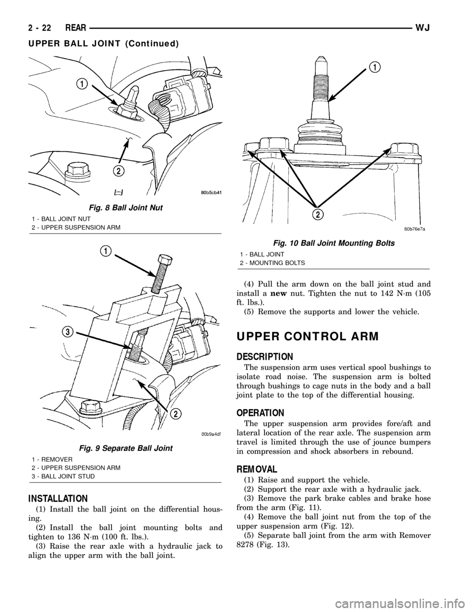
upper suspension arm (Fig. 8).
(4) Separate ball joint from the arm with Remover
8278 (Fig. 9).
NOTE: It may be necessary to strike the upper con-
trol arm with a hammer to separate the ball joint
from the arm.
(5) Remove the ball joint mounting bolts (Fig.
10)from the differential housing.
(6) Remove the ball joint from the differential
housing.
Fig. 6 Isolator Spring Locator - Typical
1 - LOWER ISOLATOR
2 - SPRING LOCATOR
3 - COIL SPRING
Fig. 7 Rear Stabilizer Bar
1 - LINK
2 - RETAINER
3 - BUSHING
4 - STABILIZER BAR
WJREAR 2 - 21
SPRING (Continued)
Page 43 of 2199
INSTALLATION
(1) Install the ball joint on the differential hous-
ing.
(2) Install the ball joint mounting bolts and
tighten to 136 N´m (100 ft. lbs.).
(3) Raise the rear axle with a hydraulic jack to
align the upper arm with the ball joint.(4) Pull the arm down on the ball joint stud and
install anewnut. Tighten the nut to 142 N´m (105
ft. lbs.).
(5) Remove the supports and lower the vehicle.
UPPER CONTROL ARM
DESCRIPTION
The suspension arm uses vertical spool bushings to
isolate road noise. The suspension arm is bolted
through bushings to cage nuts in the body and a ball
joint plate to the top of the differential housing.
OPERATION
The upper suspension arm provides fore/aft and
lateral location of the rear axle. The suspension arm
travel is limited through the use of jounce bumpers
in compression and shock absorbers in rebound.
REMOVAL
(1) Raise and support the vehicle.
(2) Support the rear axle with a hydraulic jack.
(3) Remove the park brake cables and brake hose
from the arm (Fig. 11).
(4) Remove the ball joint nut from the top of the
upper suspension arm (Fig. 12).
(5) Separate ball joint from the arm with Remover
8278 (Fig. 13).
Fig. 8 Ball Joint Nut
1 - BALL JOINT NUT
2 - UPPER SUSPENSION ARM
Fig. 9 Separate Ball Joint
1 - REMOVER
2 - UPPER SUSPENSION ARM
3 - BALL JOINT STUD
Fig. 10 Ball Joint Mounting Bolts
1 - BALL JOINT
2 - MOUNTING BOLTS
2 - 22 REARWJ
UPPER BALL JOINT (Continued)
Page 46 of 2199
DIFFERENTIAL & DRIVELINE
TABLE OF CONTENTS
page page
PROPELLER SHAFT......................1
FRONT TUBE AXLE......................14
FRONT AXLE - 186FBI....................15REAR AXLE - 198RBI.....................50
REAR AXLE - 226RBA....................90
PROPELLER SHAFT
TABLE OF CONTENTS
page page
PROPELLER SHAFT
DIAGNOSIS AND TESTING................1
STANDARD PROCEDURES................3
SPECIFICATIONS........................5
SPECIAL TOOLS........................5
PROPELLER SHAFT - FRONT
REMOVAL.............................6
INSTALLATION..........................6
PROPELLER SHAFT - FRONT 4.7L
REMOVAL.............................6INSTALLATION..........................7
PROPELLER SHAFT - REAR
REMOVAL.............................7
INSTALLATION..........................7
SINGLE CARDAN UNIVERSAL JOINTS
DISASSEMBLY..........................8
ASSEMBLY.............................9
DOUBLE CARDAN UNIVERSAL JOINTS
DISASSEMBLY..........................9
ASSEMBLY............................10
PROPELLER SHAFT
DIAGNOSIS AND TESTING
VIBRATION
Tires that are out-of-round, or wheels that are
unbalanced, will cause a low frequency vibration.
(Refer to 22 - TIRES/WHEELS - DIAGNOSIS AND
TESTING)
Brake rotors that are unbalanced will cause a
harsh, low frequency vibration. (Refer to 5 - BRAKES
- DIAGNOSIS AND TESTING)Driveline vibration can also result from loose or
damaged engine mounts.
Propeller shaft vibration increases as the vehicle
speed is increased. A vibration that occurs within a
specific speed range is not usually caused by a pro-
peller shaft being unbalanced. Defective universal
joints, or an incorrect propeller shaft angle, are usu-
ally the cause of such a vibration.
WJDIFFERENTIAL & DRIVELINE 3 - 1
Page 61 of 2199
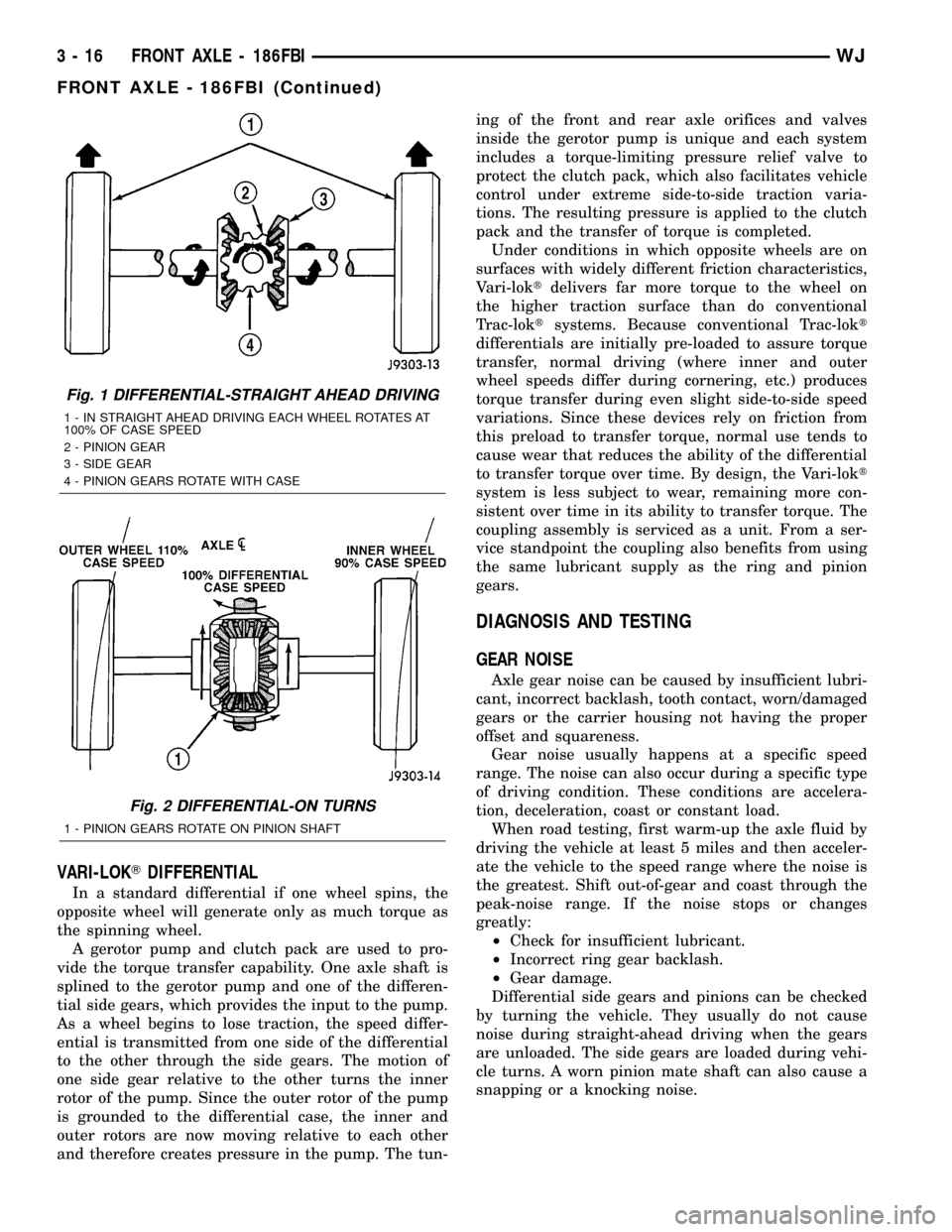
VARI-LOKTDIFFERENTIAL
In a standard differential if one wheel spins, the
opposite wheel will generate only as much torque as
the spinning wheel.
A gerotor pump and clutch pack are used to pro-
vide the torque transfer capability. One axle shaft is
splined to the gerotor pump and one of the differen-
tial side gears, which provides the input to the pump.
As a wheel begins to lose traction, the speed differ-
ential is transmitted from one side of the differential
to the other through the side gears. The motion of
one side gear relative to the other turns the inner
rotor of the pump. Since the outer rotor of the pump
is grounded to the differential case, the inner and
outer rotors are now moving relative to each other
and therefore creates pressure in the pump. The tun-ing of the front and rear axle orifices and valves
inside the gerotor pump is unique and each system
includes a torque-limiting pressure relief valve to
protect the clutch pack, which also facilitates vehicle
control under extreme side-to-side traction varia-
tions. The resulting pressure is applied to the clutch
pack and the transfer of torque is completed.
Under conditions in which opposite wheels are on
surfaces with widely different friction characteristics,
Vari-loktdelivers far more torque to the wheel on
the higher traction surface than do conventional
Trac-loktsystems. Because conventional Trac-lokt
differentials are initially pre-loaded to assure torque
transfer, normal driving (where inner and outer
wheel speeds differ during cornering, etc.) produces
torque transfer during even slight side-to-side speed
variations. Since these devices rely on friction from
this preload to transfer torque, normal use tends to
cause wear that reduces the ability of the differential
to transfer torque over time. By design, the Vari-lokt
system is less subject to wear, remaining more con-
sistent over time in its ability to transfer torque. The
coupling assembly is serviced as a unit. From a ser-
vice standpoint the coupling also benefits from using
the same lubricant supply as the ring and pinion
gears.
DIAGNOSIS AND TESTING
GEAR NOISE
Axle gear noise can be caused by insufficient lubri-
cant, incorrect backlash, tooth contact, worn/damaged
gears or the carrier housing not having the proper
offset and squareness.
Gear noise usually happens at a specific speed
range. The noise can also occur during a specific type
of driving condition. These conditions are accelera-
tion, deceleration, coast or constant load.
When road testing, first warm-up the axle fluid by
driving the vehicle at least 5 miles and then acceler-
ate the vehicle to the speed range where the noise is
the greatest. Shift out-of-gear and coast through the
peak-noise range. If the noise stops or changes
greatly:
²Check for insufficient lubricant.
²Incorrect ring gear backlash.
²Gear damage.
Differential side gears and pinions can be checked
by turning the vehicle. They usually do not cause
noise during straight-ahead driving when the gears
are unloaded. The side gears are loaded during vehi-
cle turns. A worn pinion mate shaft can also cause a
snapping or a knocking noise.
Fig. 1 DIFFERENTIAL-STRAIGHT AHEAD DRIVING
1 - IN STRAIGHT AHEAD DRIVING EACH WHEEL ROTATES AT
100% OF CASE SPEED
2 - PINION GEAR
3 - SIDE GEAR
4 - PINION GEARS ROTATE WITH CASE
Fig. 2 DIFFERENTIAL-ON TURNS
1 - PINION GEARS ROTATE ON PINION SHAFT
3 - 16 FRONT AXLE - 186FBIWJ
FRONT AXLE - 186FBI (Continued)
Page 62 of 2199
BEARING NOISE
The axle shaft, differential and pinion bearings can
all produce noise when worn or damaged. Bearing
noise can be either a whining or a growling sound.
Pinion bearings have a constant-pitch noise. This
noise changes only with vehicle speed. Pinion bearing
noise will be higher pitched because it rotates at a
faster rate. Drive the vehicle and load the differen-
tial. If bearing noise occurs, the rear pinion bearing
is the source of the noise. If the bearing noise is
heard during a coast, the front pinion bearing is the
source.
Worn or damaged differential bearings usually pro-
duce a low pitch noise. Differential bearing noise is
similar to pinion bearing noise. The pitch of differen-
tial bearing noise is also constant and varies only
with vehicle speed.
Axle shaft bearings produce noise and vibration
when worn or damaged. The noise generally changes
when the bearings are loaded. Road test the vehicle.
Turn the vehicle sharply to the left and to the right.
This will load the bearings and change the noise
level. Where axle bearing damage is slight, the noise
is usually not noticeable at speeds above 30 mph.
LOW SPEED KNOCK
Low speed knock is generally caused by a worn
U-joint or by worn side-gear thrust washers. A worn
pinion shaft bore will also cause low speed knock.
VIBRATION
Vibration at the rear of the vehicle is usually
caused by a:
²Damaged drive shaft.
²Missing drive shaft balance weight(s).²Worn or out-of-balance wheels.
²Loose wheel lug nuts.
²Worn U-joint(s).
²Loose/broken springs.
²Damaged axle shaft bearing(s).
²Loose pinion gear nut.
²Excessive pinion yoke run out.
²Bent axle shaft(s).
Check for loose or damaged front±end components
or engine/transmission mounts. These components
can contribute to what appears to be a rear-end
vibration. Do not overlook engine accessories, brack-
ets and drive belts.
All driveline components should be examined
before starting any repair.
(Refer to 22 - TIRES/WHEELS - DIAGNOSIS AND
TESTING)
DRIVELINE SNAP
A snap or clunk noise when the vehicle is shifted
into gear (or the clutch engaged), can be caused by:
²High engine idle speed.
²Transmission shift operation.
²Loose engine/transmission/transfer case mounts.
²Worn U-joints.
²Loose spring mounts.
²Loose pinion gear nut and yoke.
²Excessive ring gear backlash.
²Excessive side gear to case clearance.
The source of a snap or a clunk noise can be deter-
mined with the assistance of a helper. Raise the vehi-
cle on a hoist with the wheels free to rotate. Instruct
the helper to shift the transmission into gear. Listen
for the noise, a mechanics stethoscope is helpful in
isolating the source of a noise.
WJFRONT AXLE - 186FBI 3 - 17
FRONT AXLE - 186FBI (Continued)
Page 66 of 2199
INSTALLATION
CAUTION: The weight of the vehicle must be sup-
ported by the springs before suspension arms and
track bar fasteners can be tightened. If springs are
not at their normal ride position, ride height and
handling could be affected.
(1) Install the springs and retainer clips. Tighten
the retainer bolts to 21 N´m (16 ft. lbs.).
(2) Support the axle on a lifting device and posi-
tion axle under the vehicle.
(3) Raise the axle and align it with the spring
pads.
(4) Position the upper and lower suspension arms
in the axle brackets. Loosely install bolts and nuts to
hold suspension arms to the axle brackets.
(5) Install vent hose to the axle shaft tube.
(6) Install track bar in the axle bracket and install
the bolt loosely.
(7) Install shock absorbers and tighten the bolts to
23 N´m (17 ft. lbs.).
(8) Install stabilizer bar links to the axle brackets
and tighten the nuts to 95 N´m (70 ft. lbs.).
(9) Install drag link and tie rod to the steering
knuckles.
(10) Install steering damper to the axle bracket
and tighten the nut to 75 N´m (55 ft. lbs.).
(11) Install the brake rotors (Refer to 5 - BRAKES/
HYDRAULIC/MECHANICAL/ROTORS - INSTALLA-
TION) and calipers.
(12) Connect the wheel speed sensor wiring har-
ness to the vehicle wiring harness.
(13) Align the previously made marks on the pro-
peller shaft and the yoke/pinion flange.
(14) Install propeller shaft to pinion flange bolts ,
if equipped.
(15) Install propeller shaft to yoke straps and
bolts, if equipped.
(16) Check and fill axle lubricant.
(17) Install the wheel and tire assemblies.
(18) Remove the lifting device from the axle and
lower the vehicle.
(19) Tighten the upper suspension arm nuts to 75
N´m (55 ft. lbs.). Tighten the lower suspension arm
nuts to 115 N´m (85 ft. lbs.).
(20) Tighten the track bar bolt at the axle bracket
to 100 N´m (74 ft. lbs.).
(21) Check the front wheel alignment.
ADJUSTMENTS
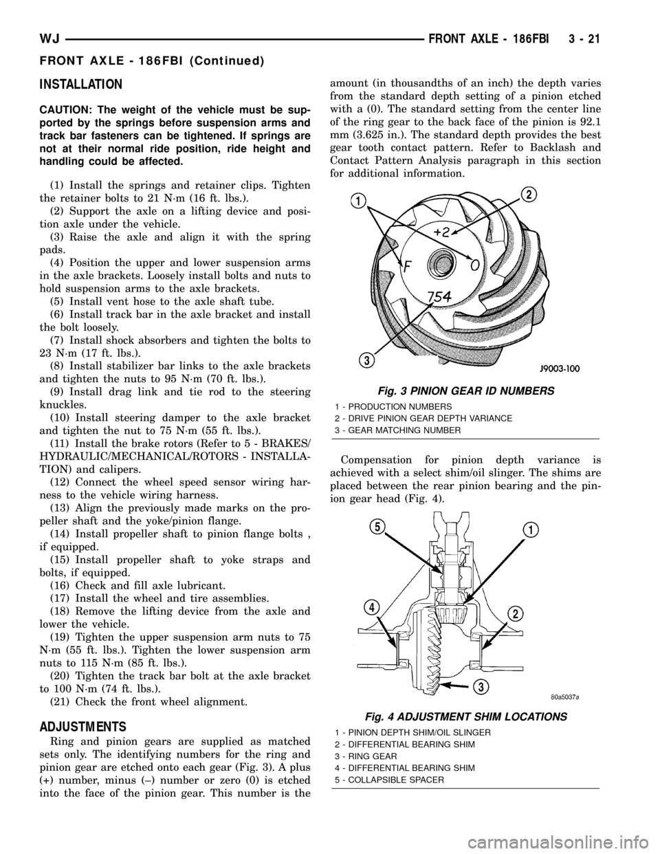
Ring and pinion gears are supplied as matched
sets only. The identifying numbers for the ring and
pinion gear are etched onto each gear (Fig. 3). A plus
(+) number, minus (±) number or zero (0) is etched
into the face of the pinion gear. This number is theamount (in thousandths of an inch) the depth varies
from the standard depth setting of a pinion etched
with a (0). The standard setting from the center line
of the ring gear to the back face of the pinion is 92.1
mm (3.625 in.). The standard depth provides the best
gear tooth contact pattern. Refer to Backlash and
Contact Pattern Analysis paragraph in this section
for additional information.
Compensation for pinion depth variance is
achieved with a select shim/oil slinger. The shims are
placed between the rear pinion bearing and the pin-
ion gear head (Fig. 4).
Fig. 3 PINION GEAR ID NUMBERS
1 - PRODUCTION NUMBERS
2 - DRIVE PINION GEAR DEPTH VARIANCE
3 - GEAR MATCHING NUMBER
Fig. 4 ADJUSTMENT SHIM LOCATIONS
1 - PINION DEPTH SHIM/OIL SLINGER
2 - DIFFERENTIAL BEARING SHIM
3 - RING GEAR
4 - DIFFERENTIAL BEARING SHIM
5 - COLLAPSIBLE SPACER
WJFRONT AXLE - 186FBI 3 - 21
FRONT AXLE - 186FBI (Continued)
Page 67 of 2199
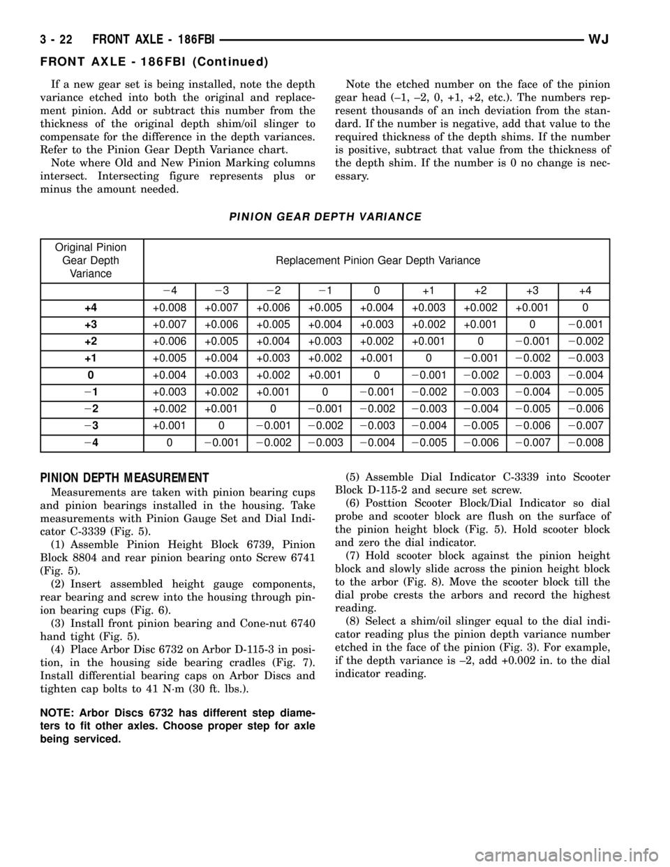
If a new gear set is being installed, note the depth
variance etched into both the original and replace-
ment pinion. Add or subtract this number from the
thickness of the original depth shim/oil slinger to
compensate for the difference in the depth variances.
Refer to the Pinion Gear Depth Variance chart.
Note where Old and New Pinion Marking columns
intersect. Intersecting figure represents plus or
minus the amount needed.Note the etched number on the face of the pinion
gear head (±1, ±2, 0, +1, +2, etc.). The numbers rep-
resent thousands of an inch deviation from the stan-
dard. If the number is negative, add that value to the
required thickness of the depth shims. If the number
is positive, subtract that value from the thickness of
the depth shim. If the number is 0 no change is nec-
essary.
PINION GEAR DEPTH VARIANCE
Original Pinion
Gear Depth
VarianceReplacement Pinion Gear Depth Variance
24232221 0 +1 +2 +3 +4
+4+0.008 +0.007 +0.006 +0.005 +0.004 +0.003 +0.002 +0.001 0
+3+0.007 +0.006 +0.005 +0.004 +0.003 +0.002 +0.001 020.001
+2+0.006 +0.005 +0.004 +0.003 +0.002 +0.001 020.00120.002
+1+0.005 +0.004 +0.003 +0.002 +0.001 020.00120.00220.003
0+0.004 +0.003 +0.002 +0.001 020.00120.00220.00320.004
21+0.003 +0.002 +0.001 020.00120.00220.00320.00420.005
22+0.002 +0.001 020.00120.00220.00320.00420.00520.006
23+0.001 020.00120.00220.00320.00420.00520.00620.007
24020.00120.00220.00320.00420.00520.00620.00720.008
PINION DEPTH MEASUREMENT
Measurements are taken with pinion bearing cups
and pinion bearings installed in the housing. Take
measurements with Pinion Gauge Set and Dial Indi-
cator C-3339 (Fig. 5).
(1) Assemble Pinion Height Block 6739, Pinion
Block 8804 and rear pinion bearing onto Screw 6741
(Fig. 5).
(2) Insert assembled height gauge components,
rear bearing and screw into the housing through pin-
ion bearing cups (Fig. 6).
(3) Install front pinion bearing and Cone-nut 6740
hand tight (Fig. 5).
(4) Place Arbor Disc 6732 on Arbor D-115-3 in posi-
tion, in the housing side bearing cradles (Fig. 7).
Install differential bearing caps on Arbor Discs and
tighten cap bolts to 41 N´m (30 ft. lbs.).
NOTE: Arbor Discs 6732 has different step diame-
ters to fit other axles. Choose proper step for axle
being serviced.(5) Assemble Dial Indicator C-3339 into Scooter
Block D-115-2 and secure set screw.
(6) Posttion Scooter Block/Dial Indicator so dial
probe and scooter block are flush on the surface of
the pinion height block (Fig. 5). Hold scooter block
and zero the dial indicator.
(7) Hold scooter block against the pinion height
block and slowly slide across the pinion height block
to the arbor (Fig. 8). Move the scooter block till the
dial probe crests the arbors and record the highest
reading.
(8) Select a shim/oil slinger equal to the dial indi-
cator reading plus the pinion depth variance number
etched in the face of the pinion (Fig. 3). For example,
if the depth variance is ±2, add +0.002 in. to the dial
indicator reading.
3 - 22 FRONT AXLE - 186FBIWJ
FRONT AXLE - 186FBI (Continued)
Page 70 of 2199
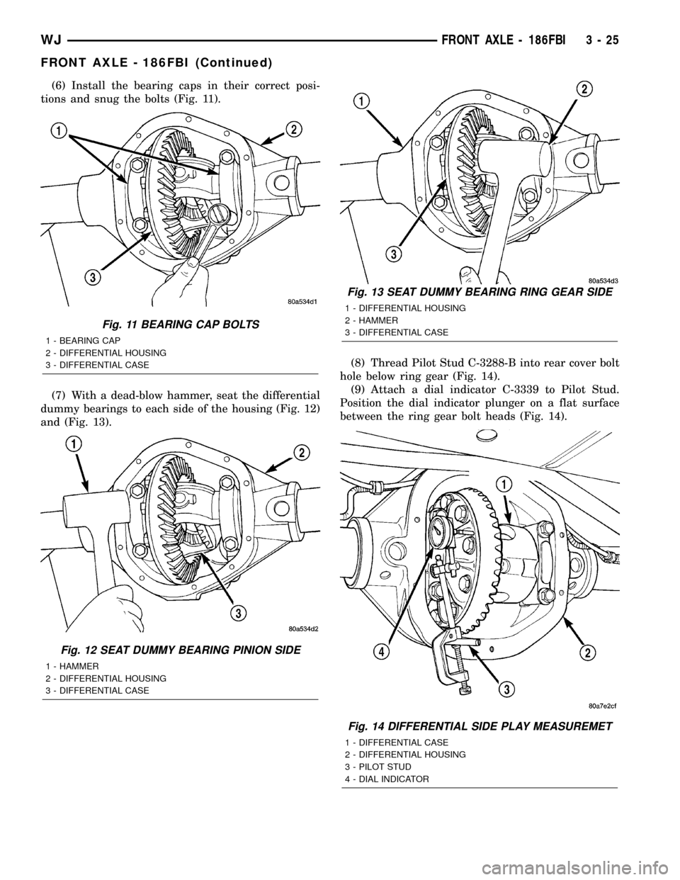
(6) Install the bearing caps in their correct posi-
tions and snug the bolts (Fig. 11).
(7) With a dead-blow hammer, seat the differential
dummy bearings to each side of the housing (Fig. 12)
and (Fig. 13).(8) Thread Pilot Stud C-3288-B into rear cover bolt
hole below ring gear (Fig. 14).
(9) Attach a dial indicator C-3339 to Pilot Stud.
Position the dial indicator plunger on a flat surface
between the ring gear bolt heads (Fig. 14).
Fig. 11 BEARING CAP BOLTS
1 - BEARING CAP
2 - DIFFERENTIAL HOUSING
3 - DIFFERENTIAL CASE
Fig. 12 SEAT DUMMY BEARING PINION SIDE
1 - HAMMER
2 - DIFFERENTIAL HOUSING
3 - DIFFERENTIAL CASE
Fig. 13 SEAT DUMMY BEARING RING GEAR SIDE
1 - DIFFERENTIAL HOUSING
2 - HAMMER
3 - DIFFERENTIAL CASE
Fig. 14 DIFFERENTIAL SIDE PLAY MEASUREMET
1 - DIFFERENTIAL CASE
2 - DIFFERENTIAL HOUSING
3 - PILOT STUD
4 - DIAL INDICATOR
WJFRONT AXLE - 186FBI 3 - 25
FRONT AXLE - 186FBI (Continued)
Page 93 of 2199
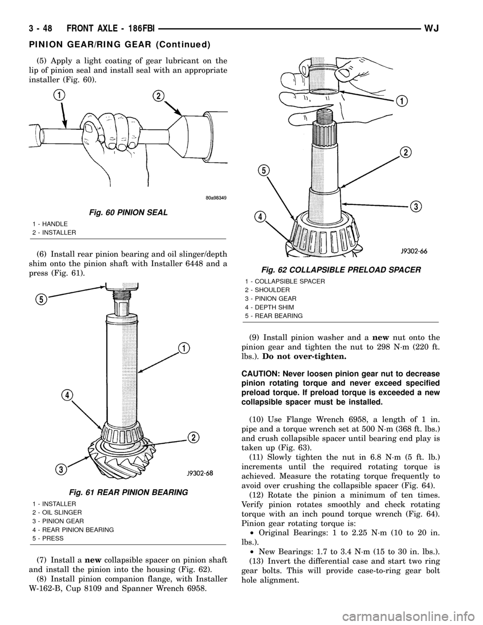
(5) Apply a light coating of gear lubricant on the
lip of pinion seal and install seal with an appropriate
installer (Fig. 60).
(6) Install rear pinion bearing and oil slinger/depth
shim onto the pinion shaft with Installer 6448 and a
press (Fig. 61).
(7) Install anewcollapsible spacer on pinion shaft
and install the pinion into the housing (Fig. 62).
(8) Install pinion companion flange, with Installer
W-162-B, Cup 8109 and Spanner Wrench 6958.(9) Install pinion washer and anewnut onto the
pinion gear and tighten the nut to 298 N´m (220 ft.
lbs.).Do not over-tighten.
CAUTION: Never loosen pinion gear nut to decrease
pinion rotating torque and never exceed specified
preload torque. If preload torque is exceeded a new
collapsible spacer must be installed.
(10) Use Flange Wrench 6958, a length of 1 in.
pipe and a torque wrench set at 500 N´m (368 ft. lbs.)
and crush collapsible spacer until bearing end play is
taken up (Fig. 63).
(11) Slowly tighten the nut in 6.8 N´m (5 ft. lb.)
increments until the required rotating torque is
achieved. Measure the rotating torque frequently to
avoid over crushing the collapsible spacer (Fig. 64).
(12) Rotate the pinion a minimum of ten times.
Verify pinion rotates smoothly and check rotating
torque with an inch pound torque wrench (Fig. 64).
Pinion gear rotating torque is:
²Original Bearings: 1 to 2.25 N´m (10 to 20 in.
lbs.).
²New Bearings: 1.7 to 3.4 N´m (15 to 30 in. lbs.).
(13) Invert the differential case and start two ring
gear bolts. This will provide case-to-ring gear bolt
hole alignment.
Fig. 60 PINION SEAL
1 - HANDLE
2 - INSTALLER
Fig. 61 REAR PINION BEARING
1 - INSTALLER
2 - OIL SLINGER
3 - PINION GEAR
4 - REAR PINION BEARING
5 - PRESS
Fig. 62 COLLAPSIBLE PRELOAD SPACER
1 - COLLAPSIBLE SPACER
2 - SHOULDER
3 - PINION GEAR
4 - DEPTH SHIM
5 - REAR BEARING
3 - 48 FRONT AXLE - 186FBIWJ
PINION GEAR/RING GEAR (Continued)