Timing chain JEEP GRAND CHEROKEE 2002 WJ / 2.G Workshop Manual
[x] Cancel search | Manufacturer: JEEP, Model Year: 2002, Model line: GRAND CHEROKEE, Model: JEEP GRAND CHEROKEE 2002 WJ / 2.GPages: 2199, PDF Size: 76.01 MB
Page 239 of 2199
ACCESSORY DRIVE
TABLE OF CONTENTS
page page
BELT TENSIONERS
REMOVAL
REMOVALÐ4.7L ENGINE...............16
REMOVALÐ4.0L ENGINE...............16
INSTALLATION
INSTALLATIONÐ4.7L ENGINE...........16
INSTALLATIONÐ4.0L ENGINE...........17
DRIVE BELTS - 4.0L
DIAGNOSIS AND TESTING ± SERPENTINE
DRIVE BELT.........................17REMOVALÐ4.0L ENGINE.................19
INSTALLATIONÐ4.0L ENGINE.............19
DRIVE BELTS - 4.7L
DIAGNOSIS AND TESTING ± SERPENTINE
DRIVE BELT.........................20
REMOVAL - 4.7L ENGINE.................22
INSTALLATION - 4.7L ENGINE.............23
BELT TENSIONERS
REMOVAL
REMOVALÐ4.7L ENGINE
(1) Remove accessory drive belt (Refer to 7 -
COOLING/ACCESSORY DRIVE/DRIVE BELTS -
REMOVAL).
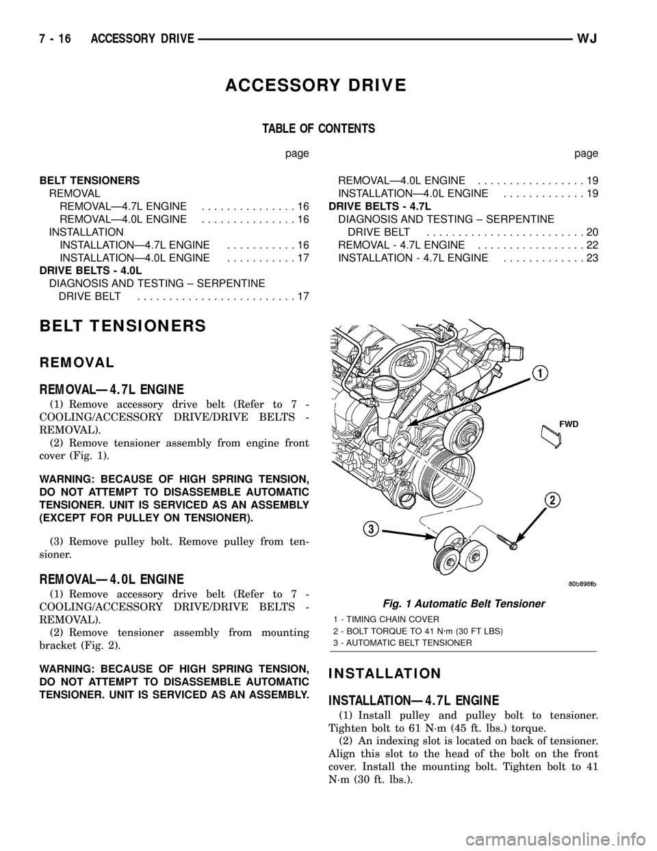
(2) Remove tensioner assembly from engine front
cover (Fig. 1).
WARNING: BECAUSE OF HIGH SPRING TENSION,
DO NOT ATTEMPT TO DISASSEMBLE AUTOMATIC
TENSIONER. UNIT IS SERVICED AS AN ASSEMBLY
(EXCEPT FOR PULLEY ON TENSIONER).
(3) Remove pulley bolt. Remove pulley from ten-
sioner.
REMOVALÐ4.0L ENGINE
(1) Remove accessory drive belt (Refer to 7 -
COOLING/ACCESSORY DRIVE/DRIVE BELTS -
REMOVAL).
(2) Remove tensioner assembly from mounting
bracket (Fig. 2).
WARNING: BECAUSE OF HIGH SPRING TENSION,
DO NOT ATTEMPT TO DISASSEMBLE AUTOMATIC
TENSIONER. UNIT IS SERVICED AS AN ASSEMBLY.
INSTALLATION
INSTALLATIONÐ4.7L ENGINE
(1) Install pulley and pulley bolt to tensioner.
Tighten bolt to 61 N´m (45 ft. lbs.) torque.
(2) An indexing slot is located on back of tensioner.
Align this slot to the head of the bolt on the front
cover. Install the mounting bolt. Tighten bolt to 41
N´m (30 ft. lbs.).
Fig. 1 Automatic Belt Tensioner
1 - TIMING CHAIN COVER
2 - BOLT TORQUE TO 41 N´m (30 FT LBS)
3 - AUTOMATIC BELT TENSIONER
7 - 16 ACCESSORY DRIVEWJ
Page 262 of 2199
(5) Install electrical connector to coolant tempera-
ture sensor.
(6) Be sure that the radiator draincock is tightly
closed. Fill the cooling system to the correct levelwith the required coolant mixture (Refer to 7 -
COOLING - STANDARD PROCEDURE).
(7) Start and warm the engine. Check for leaks.
INSTALLATIONÐ4.7L ENGINE
(1) Clean mating areas of timing chain cover and
thermostat housing.
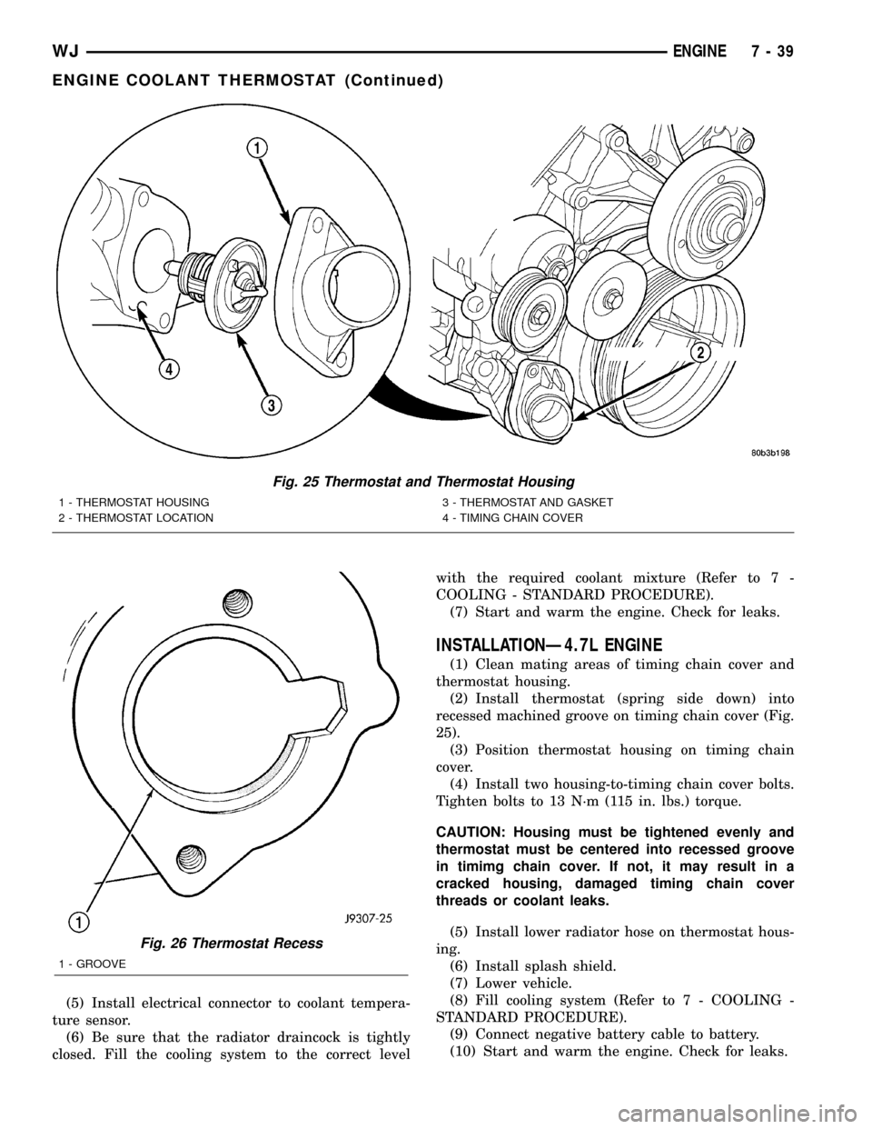
(2) Install thermostat (spring side down) into
recessed machined groove on timing chain cover (Fig.
25).
(3) Position thermostat housing on timing chain
cover.
(4) Install two housing-to-timing chain cover bolts.
Tighten bolts to 13 N´m (115 in. lbs.) torque.
CAUTION: Housing must be tightened evenly and
thermostat must be centered into recessed groove
in timimg chain cover. If not, it may result in a
cracked housing, damaged timing chain cover
threads or coolant leaks.
(5) Install lower radiator hose on thermostat hous-
ing.
(6) Install splash shield.
(7) Lower vehicle.
(8) Fill cooling system (Refer to 7 - COOLING -
STANDARD PROCEDURE).
(9) Connect negative battery cable to battery.
(10) Start and warm the engine. Check for leaks.
Fig. 25 Thermostat and Thermostat Housing
1 - THERMOSTAT HOUSING
2 - THERMOSTAT LOCATION3 - THERMOSTAT AND GASKET
4 - TIMING CHAIN COVER
Fig. 26 Thermostat Recess
1 - GROOVE
WJENGINE 7 - 39
ENGINE COOLANT THERMOSTAT (Continued)
Page 270 of 2199
INSPECTION
The radiator cooling fins should be checked for
damage or deterioration. Inspect cooling fins to make
sure they are not bent or crushed, these areas result
in reduced heat exchange causing the cooling system
to operate at higher temperatures. Inspect the plastic
end tanks for cracks, damage or leaks.
Inspect the radiator neck for damage or distortion.
INSTALLATION
CAUTION: Before installing the radiator or A/C con-
denser, be sure the radiator-to-body and radiator-to-
A/C condenser rubber air seals (Fig. 39) are
properly fastened to their original positions. These
are used at the top, bottom and sides of the radia-
tor and A/C condenser. To prevent overheating,
these seals must be installed to their original posi-
tions.
(1) Equipped with air conditioning: Gently lower
the radiator into the vehicle. Guide the two radiator
alignment dowels through the holes in the rubber air
seals first and then through the A/C support brackets
(Fig. 40). Continue to guide the alignment dowels
into the rubber grommets located in lower radiator
crossmember. The holes in the L-shaped brackets
(located on bottom of A/C condenser) must be posi-
tioned between bottom of rubber air seals and top of
rubber grommets.
(2) Connect the radiator upper and lower hoses
and hose clamps to radiator (Fig. 41).
CAUTION: The tangs on the hose clamps must be
positioned straight down.
(3) Install coolant reserve/overflow tank hose at
radiator (Fig. 41).
(4) Connect both transmission cooler lines at the
radiator (Fig. 41).
(5) Install both radiator mounting bolts (Fig. 41).
(6) Install air inlet duct at grill.
(7) Attach electric fan harness to shroud, then con-
nect harness to connector (Fig. 41).
(8) Install the grill (Refer to 23 - BODY/EXTERI-
OR/GRILLE - INSTALLATION).
(9) Install the fan/viscous fan drive assembly to
the water pump.
(10) Rotate the fan blades (by hand) and check for
interference at fan shroud.
(11) Be sure of at least 25 mm (1.0 inch) between
tips of fan blades and fan shroud.
(12) Fill cooling system (Refer to 7 - COOLING -
STANDARD PROCEDURE).
(13) Connect battery cable at battery.
(14) Start and warm engine. Check for leaks.
RADIATOR FAN MOTOR
DIAGNOSIS AND TESTINGÐELECTRIC
COOLING FAN
The powertrain control module (PCM) will enter a
diagnostic trouble code (DTC) in memory if it detects
a problem in the auxiliary cooling fan relay or circuit.
(Refer to 25 - EMISSIONS CONTROL - DESCRIP-
TION).
If the electric cooling fan is inoperative, check the
15A fuse in the junction block and the 40A fuse in
the Power Distribution Center (PDC) with a 12 volt
test lamp or DVOM. Refer to the inside of the PDC
cover for the exact location of the fuse. If fuses are
okay, refer to ELECTRICAL for cooling fan and relay
circuit schematic.
WATER PUMP - 4.7L
DESCRIPTION
DESCRIPTIONÐWATER PUMP
A centrifugal water pump circulates coolant
through the water jackets, passages, intake manifold,
radiator core, cooling system hoses and heater core.
The pump is driven from the engine crankshaft by a
single serpentine drive belt.
The water pump impeller is pressed onto the rear
of a shaft that rotates in bearings pressed into the
housing. The housing has two small holes to allow
seepage to escape. The water pump seals are lubri-
cated by the antifreeze in the coolant mixture. No
additional lubrication is necessary.
Both heater hoses are connected to fittings on the
timing chain front cover. The water pump is also
mounted directly to the timing chain cover and is
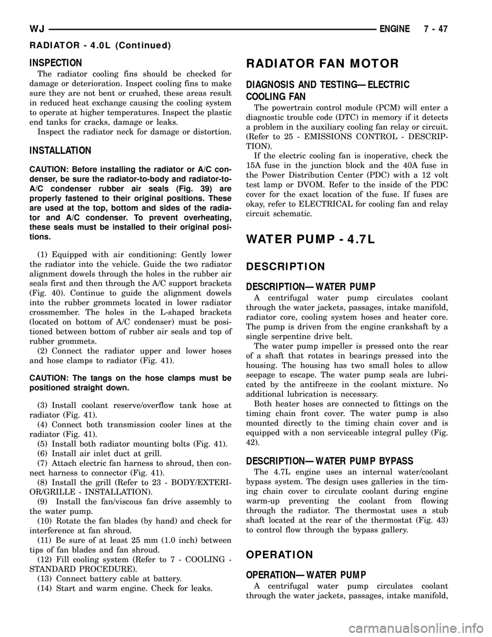
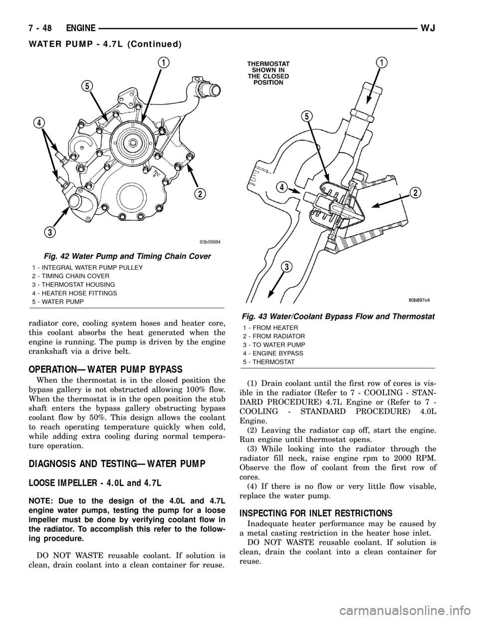
equipped with a non serviceable integral pulley (Fig.
42).
DESCRIPTIONÐWATER PUMP BYPASS
The 4.7L engine uses an internal water/coolant
bypass system. The design uses galleries in the tim-
ing chain cover to circulate coolant during engine
warm-up preventing the coolant from flowing
through the radiator. The thermostat uses a stub
shaft located at the rear of the thermostat (Fig. 43)
to control flow through the bypass gallery.
OPERATION
OPERATIONÐWATER PUMP
A centrifugal water pump circulates coolant
through the water jackets, passages, intake manifold,
WJENGINE 7 - 47
RADIATOR - 4.0L (Continued)
Page 271 of 2199
radiator core, cooling system hoses and heater core,
this coolant absorbs the heat generated when the
engine is running. The pump is driven by the engine
crankshaft via a drive belt.
OPERATIONÐWATER PUMP BYPASS
When the thermostat is in the closed position the
bypass gallery is not obstructed allowing 100% flow.
When the thermostat is in the open position the stub
shaft enters the bypass gallery obstructing bypass
coolant flow by 50%. This design allows the coolant
to reach operating temperature quickly when cold,
while adding extra cooling during normal tempera-
ture operation.
DIAGNOSIS AND TESTINGÐWATER PUMP
LOOSE IMPELLER - 4.0L and 4.7L
NOTE: Due to the design of the 4.0L and 4.7L
engine water pumps, testing the pump for a loose
impeller must be done by verifying coolant flow in
the radiator. To accomplish this refer to the follow-
ing procedure.
DO NOT WASTE reusable coolant. If solution is
clean, drain coolant into a clean container for reuse.(1) Drain coolant until the first row of cores is vis-
ible in the radiator (Refer to 7 - COOLING - STAN-
DARD PROCEDURE) 4.7L Engine or (Refer to 7 -
COOLING - STANDARD PROCEDURE) 4.0L
Engine.
(2) Leaving the radiator cap off, start the engine.
Run engine until thermostat opens.
(3) While looking into the radiator through the
radiator fill neck, raise engine rpm to 2000 RPM.
Observe the flow of coolant from the first row of
cores.
(4) If there is no flow or very little flow visable,
replace the water pump.
INSPECTING FOR INLET RESTRICTIONS
Inadequate heater performance may be caused by
a metal casting restriction in the heater hose inlet.
DO NOT WASTE reusable coolant. If solution is
clean, drain the coolant into a clean container for
reuse.
Fig. 42 Water Pump and Timing Chain Cover
1 - INTEGRAL WATER PUMP PULLEY
2 - TIMING CHAIN COVER
3 - THERMOSTAT HOUSING
4 - HEATER HOSE FITTINGS
5 - WATER PUMP
Fig. 43 Water/Coolant Bypass Flow and Thermostat
1 - FROM HEATER
2 - FROM RADIATOR
3 - TO WATER PUMP
4 - ENGINE BYPASS
5 - THERMOSTAT
7 - 48 ENGINEWJ
WATER PUMP - 4.7L (Continued)
Page 272 of 2199
WARNING: DO NOT LOOSEN THE RADIATOR
DRAINCOCK WITH THE SYSTEM HOT AND UNDER
PRESSURE. SERIOUS BURNS FROM THE COOL-
ANT CAN OCCUR.
(1) Drain sufficient coolant from the radiator to
decrease the level below the heater hose inlet. On
4.7L engines this requires complete draining.
(2) Remove the heater hose.
(3) Inspect the inlet for metal casting flash or
other restrictions.
NOTE: On 4.0L engines remove the pump from the
engine before removing restriction to prevent con-
tamination of the coolant with debris. . On 4.7L
engine remove the fitting from the timing chain
cover, If the restriction is in the timing chain cover,
remove the timing chain cover.
REMOVAL
The water pump on 4.7L engines is bolted directly
to the engine timing chain case/cover.
A gasket is used as a seal between the water pump
and timing chain case/cover.
The water pump can be removed without discharg-
ing the air conditioning system (if equipped).
(1) Disconnect negative battery cable from battery.
(2) Drain cooling system (Refer to 7 - COOLING -
STANDARD PROCEDURE). Do not waste reusable
coolant. If solution is clean, drain coolant into a clean
container for reuse.
WARNING: CONSTANT TENSION HOSE CLAMPS
ARE USED ON MOST COOLING SYSTEM HOSES.
WHEN REMOVING OR INSTALLING, USE ONLY
TOOLS DESIGNED FOR SERVICING THIS TYPE OF
CLAMP, SUCH AS SPECIAL CLAMP TOOL (NUMBER
6094). SNAP-ON CLAMP TOOL (NUMBER HPC-20)
MAY BE USED FOR LARGER CLAMPS. ALWAYS
WEAR SAFETY GLASSES WHEN SERVICING CON-
STANT TENSION CLAMPS.
CAUTION: A number or letter is stamped into the
tongue of constant tension clamps. If replacement
is necessary, use only an original equipment clamp
with matching number or letter.
(3) Remove accessory drive belt (Refer to 7 -
COOLING/ACCESSORY DRIVE/DRIVE BELTS -
REMOVAL).
(4) Remove lower radiator hose clamp and remove
lower hose at water pump.
(5) Remove seven water pump mounting bolts and
one stud bolt.CAUTION: Do not pry water pump at timing chain
case/cover. The machined surfaces may be dam-
aged resulting in leaks.
(6) Remove water pump and gasket. Discard gas-
ket.
CLEANING
Clean the gasket mating surface. Use caution not
to damage the gasket sealing surface.
INSPECTION
Inspect the water pump assembly for cracks in the
housing, Water leaks from shaft seal, Loose or rough
turning bearing or Impeller rubbing either the pump
body or timing chain case/cover.
INSTALLATION
(1) Clean gasket mating surfaces.
(2) Using a new gasket, position water pump and
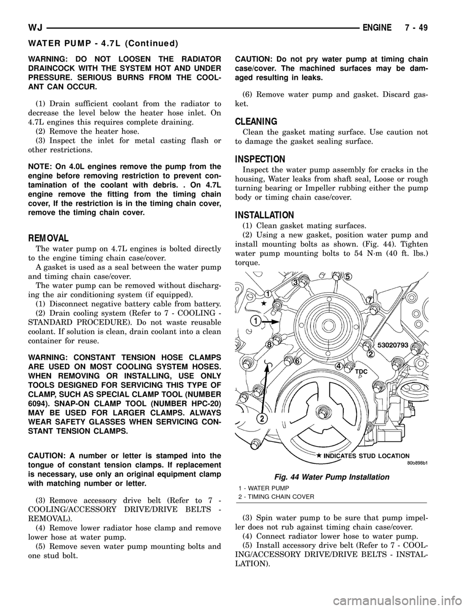
install mounting bolts as shown. (Fig. 44). Tighten
water pump mounting bolts to 54 N´m (40 ft. lbs.)
torque.
(3) Spin water pump to be sure that pump impel-
ler does not rub against timing chain case/cover.
(4) Connect radiator lower hose to water pump.
(5) Install accessory drive belt (Refer to 7 - COOL-
ING/ACCESSORY DRIVE/DRIVE BELTS - INSTAL-
LATION).
Fig. 44 Water Pump Installation
1 - WATER PUMP
2 - TIMING CHAIN COVER
WJENGINE 7 - 49
WATER PUMP - 4.7L (Continued)
Page 274 of 2199
NOTE: On 4.0L engines remove the pump from the
engine before removing restriction to prevent con-
tamination of the coolant with debris. . On 4.7L
engine remove the fitting from the timing chain
cover, If the restriction is in the timing chain cover,
remove the timing chain cover.
REMOVAL
CAUTION: If the water pump is replaced because of
mechanical damage, the fan blades and viscous fan
drive should also be inspected. These components
could have been damaged due to excessive vibra-
tion.
The water pump impeller is pressed on the rear of
the pump shaft and bearing assembly. The water
pump is serviced only as a complete assembly.
NOTE: The water pump can be replaced without
discharging the A/C system.
WARNING: DO NOT REMOVE THE BLOCK DRAIN
PLUG(S) OR LOOSEN RADIATOR DRAINCOCK
WITH THE SYSTEM HOT AND UNDER PRESSURE.
SERIOUS BURNS FROM COOLANT CAN OCCUR.
DO NOT WASTE reusable coolant. If the solution
is clean, drain coolant into a clean container for
reuse.
(1) Disconnect negative battery cable at battery.
(2) Drain the cooling system (Refer to 7 - COOL-
ING - STANDARD PROCEDURE).
(3) The thermal viscous fan drive is attached
(threaded) to the water pump hub shaft. Remove fan/
viscous fan drive assembly from water pump by turn-
ing mounting nut counterclockwise as viewed from
front. Threads on viscous fan drive areRIGHT
HANDDo not attempt to remove fan/viscous fan
drive assembly from vehicle at this time.
(4) If water pump is being replaced, do not unbolt
fan blade assembly from thermal viscous fan drive.
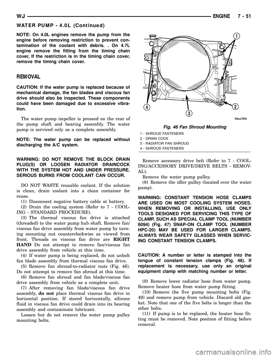
(5) Remove fan shroud-to-radiator nuts (Fig. 46).
Do not attempt to remove fan shroud at this time.
(6) Remove fan shroud and fan blade/viscous fan
drive assembly from vehicle as a complete unit.
(7) After removing fan blade/viscous fan drive
assembly,do notplace thermal viscous fan drive in
horizontal position. If stored horizontally, silicone
fluid in viscous fan drive could drain into its bearing
assembly and contaminate lubricant.
Loosen but do not remove the water pump pulley
mounting bolts.Remove accessory drive belt (Refer to 7 - COOL-
ING/ACCESSORY DRIVE/DRIVE BELTS - REMOV-
AL).
Remove the water pump pulley.
(8) Remove the idler pulley (located over the water
pump).
WARNING: CONSTANT TENSION HOSE CLAMPS
ARE USED ON MOST COOLING SYSTEM HOSES.
WHEN REMOVING OR INSTALLING, USE ONLY
TOOLS DESIGNED FOR SERVICING THIS TYPE OF
CLAMP, SUCH AS SPECIAL CLAMP TOOL (NUMBER
6094) (Fig. 47) SNAP-ON CLAMP TOOL (NUMBER
HPC-20) MAY BE USED FOR LARGER CLAMPS.
ALWAYS WEAR SAFETY GLASSES WHEN SERVIC-
ING CONSTANT TENSION CLAMPS.
CAUTION: A number or letter is stamped into the
tongue of constant tension clamps (Fig. 48). If
replacement is necessary, use only an original
equipment clamp with matching number or letter.
(9) Remove lower radiator hose from water pump.
Remove heater hose from water pump fitting.
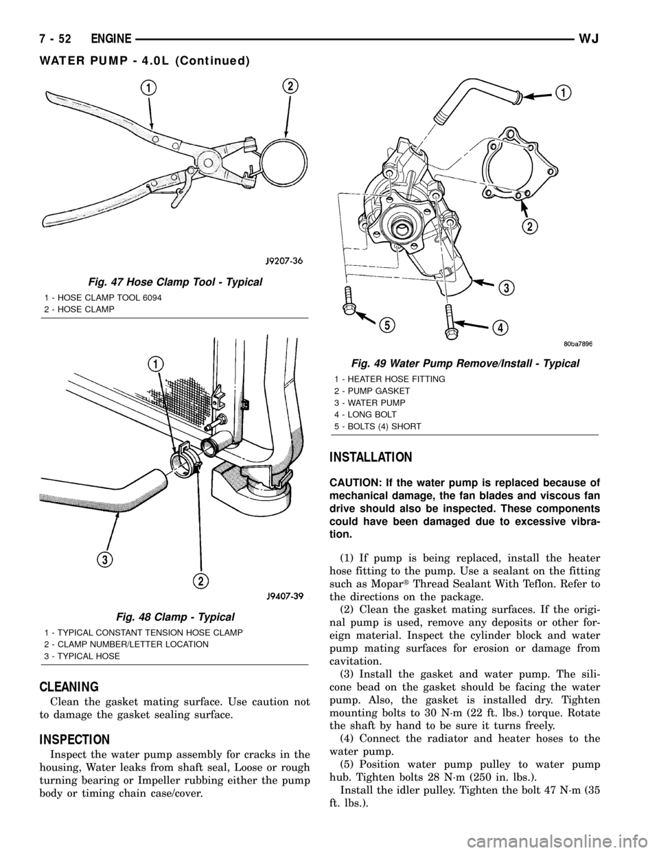
(10) Remove the five pump mounting bolts (Fig.
49) and remove pump from vehicle. Discard old gas-
ket. Note that one of the five bolts is longer than the
other bolts.
(11) If pump is to be replaced, the heater hose fit-
ting must be removed. Note position of fitting before
removal.
Fig. 46 Fan Shroud Mounting
1 - SHROUD FASTENERS
2 - DRAIN COCK
3 - RADIATOR FAN SHROUD
4 - SHROUD FASTENERS
WJENGINE 7 - 51
WATER PUMP - 4.0L (Continued)
Page 275 of 2199
CLEANING
Clean the gasket mating surface. Use caution not
to damage the gasket sealing surface.
INSPECTION
Inspect the water pump assembly for cracks in the
housing, Water leaks from shaft seal, Loose or rough
turning bearing or Impeller rubbing either the pump
body or timing chain case/cover.
INSTALLATION
CAUTION: If the water pump is replaced because of
mechanical damage, the fan blades and viscous fan
drive should also be inspected. These components
could have been damaged due to excessive vibra-
tion.
(1) If pump is being replaced, install the heater
hose fitting to the pump. Use a sealant on the fitting
such as MopartThread Sealant With Teflon. Refer to
the directions on the package.
(2) Clean the gasket mating surfaces. If the origi-
nal pump is used, remove any deposits or other for-
eign material. Inspect the cylinder block and water
pump mating surfaces for erosion or damage from
cavitation.
(3) Install the gasket and water pump. The sili-
cone bead on the gasket should be facing the water
pump. Also, the gasket is installed dry. Tighten
mounting bolts to 30 N´m (22 ft. lbs.) torque. Rotate
the shaft by hand to be sure it turns freely.
(4) Connect the radiator and heater hoses to the
water pump.
(5) Position water pump pulley to water pump
hub. Tighten bolts 28 N´m (250 in. lbs.).
Install the idler pulley. Tighten the bolt 47 N´m (35
ft. lbs.).
Fig. 47 Hose Clamp Tool - Typical
1 - HOSE CLAMP TOOL 6094
2 - HOSE CLAMP
Fig. 48 Clamp - Typical
1 - TYPICAL CONSTANT TENSION HOSE CLAMP
2 - CLAMP NUMBER/LETTER LOCATION
3 - TYPICAL HOSE
Fig. 49 Water Pump Remove/Install - Typical
1 - HEATER HOSE FITTING
2 - PUMP GASKET
3 - WATER PUMP
4 - LONG BOLT
5 - BOLTS (4) SHORT
7 - 52 ENGINEWJ
WATER PUMP - 4.0L (Continued)
Page 1245 of 2199
REMOVAL
REMOVAL - CAMSHAFT BEARINGS.......31
REMOVAL - CAMSHAFT................31
INSPECTION
INSPECTION - CAMSHAFT BEARINGS.....31
INSPECTION - CAMSHAFT..............31
INSTALLATION
INSTALLATION - CAMSHAFT BEARINGS . . . 32
INSTALLATION - CAMSHAFT............32
CONNECTING ROD BEARINGS
STANDARD PROCEDURE - FITTING
CONNECTING ROD BEARINGS..........33
CRANKSHAFT
DESCRIPTION.........................35
CRANKSHAFT MAIN BEARINGS
STANDARD PROCEDURE - FITTING
CRANKSHAFT MAIN BEARINGS..........36
REMOVAL.............................39
INSPECTION..........................40
INSTALLATION.........................40
CRANKSHAFT OIL SEAL - FRONT
REMOVAL.............................41
INSTALLATION.........................41
CRANKSHAFT OIL SEAL - REAR
REMOVAL.............................42
INSTALLATION.........................42
HYDRAULIC LIFTERS
DESCRIPTION.........................43
REMOVAL.............................43
CLEANING............................43
INSPECTION..........................43
INSTALLATION.........................43
PISTON & CONNECTING ROD
DESCRIPTION.........................44
STANDARD PROCEDURE - PISTON FITTING . 44
REMOVAL.............................45
INSTALLATION.........................46
PISTON RINGS
STANDARD PROCEDURE - PISTON RING
FITTING.............................47
VIBRATION DAMPER
REMOVAL.............................49
INSTALLATION.........................49STRUCTURAL SUPPORT
REMOVAL.............................49
INSTALLATION.........................50
LUBRICATION
DESCRIPTION.........................50
OPERATION...........................50
DIAGNOSIS AND TESTING
DIAGNOSIS AND TESTING - ENGINE OIL
PRESSURE..........................51
DIAGNOSIS AND TESTING - ENGINE OIL
LEAK...............................51
OIL
STANDARD PROCEDURE - ENGINE OIL
SERVICE............................53
OIL FILTER
REMOVAL.............................53
INSTALLATION.........................54
OIL PAN
DESCRIPTION.........................54
REMOVAL.............................54
INSTALLATION.........................55
ENGINE OIL PRESSURE SENSOR
DESCRIPTION.........................56
OPERATION...........................56
OIL PUMP
REMOVAL.............................56
INSTALLATION.........................57
INTAKE MANIFOLD
DESCRIPTION.........................57
DIAGNOSIS AND TESTING - INTAKE
MANIFOLD LEAKAGE..................57
REMOVAL.............................57
INSTALLATION.........................57
EXHAUST MANIFOLD
DESCRIPTION.........................58
REMOVAL.............................58
INSTALLATION.........................58
TIMING BELT / CHAIN COVER(S)
REMOVAL.............................58
INSTALLATION.........................58
TIMING BELT/CHAIN AND SPROCKETS
REMOVAL.............................60
INSTALLATION.........................60
ENGINE - 4.0L
DESCRIPTION
The 4.0 Liter (242 CID) six-cylinder engine is an
In-line, lightweight, overhead valve engine. This
engine is designed for unleaded fuel.
The engine cylinder head has dual quench-type
combustion chambers that create turbulence and fast
burning of the air/fuel mixture. This results in better
fuel economy.
The cylinders are numbered 1 through 6 from front
to rear. The firing order is 1-5-3-6-2-4 (Fig. 1).The crankshaft rotation is clockwise, when viewed
from the front of the engine. The crankshaft rotates
within seven main bearings. The camshaft rotates
within four bearings.
The engine Build Date Code is located on a
machined surface on the right side of the cylinder
block between the No.2 and No.3 cylinders (Fig. 2).
The digits of the code identify:
²1st DigitÐThe year (8 = 1998).
²2nd & 3rd DigitsÐThe month (01 - 12).
²4th & 5th DigitsÐThe engine type/fuel system/
compression ratio (MX = A 4.0 Liter (242 CID) 8.7:1
compression ratio engine with a multi-point fuel
injection system).
9 - 2 ENGINE - 4.0LWJ
Page 1274 of 2199
REMOVAL
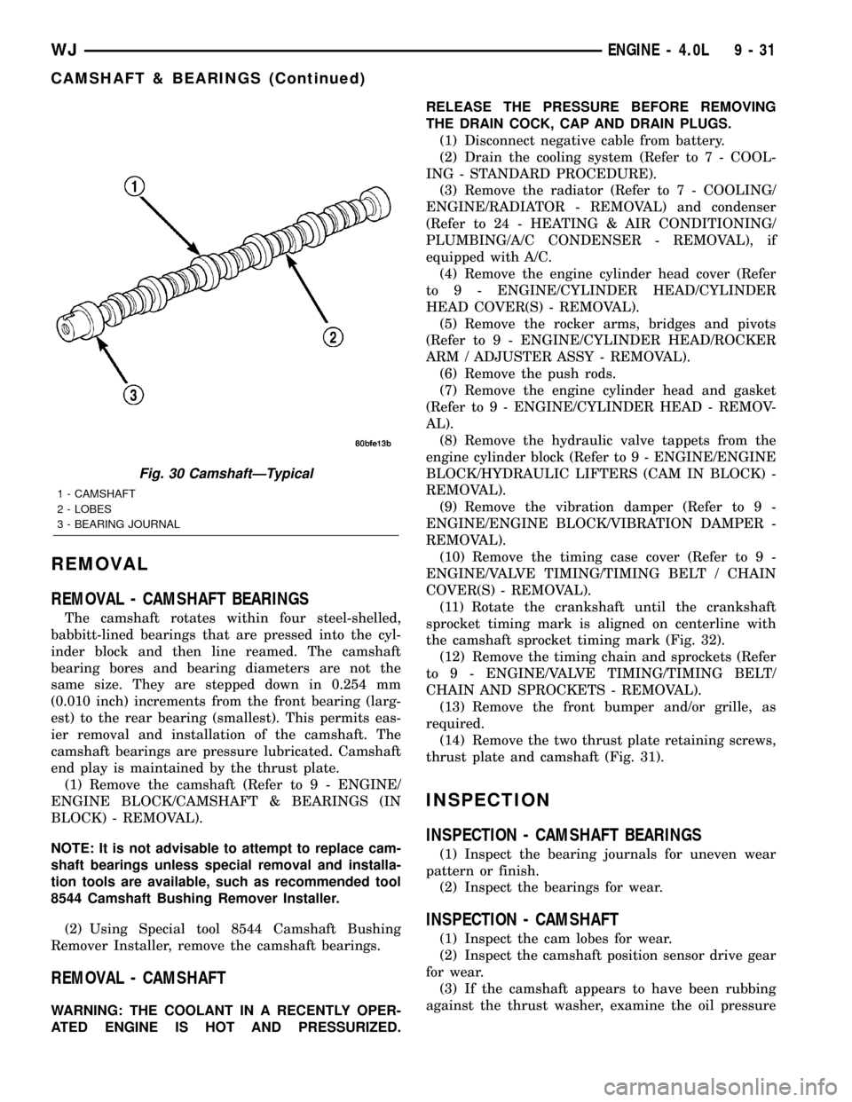
REMOVAL - CAMSHAFT BEARINGS
The camshaft rotates within four steel-shelled,
babbitt-lined bearings that are pressed into the cyl-
inder block and then line reamed. The camshaft
bearing bores and bearing diameters are not the
same size. They are stepped down in 0.254 mm
(0.010 inch) increments from the front bearing (larg-
est) to the rear bearing (smallest). This permits eas-
ier removal and installation of the camshaft. The
camshaft bearings are pressure lubricated. Camshaft
end play is maintained by the thrust plate.
(1) Remove the camshaft (Refer to 9 - ENGINE/
ENGINE BLOCK/CAMSHAFT & BEARINGS (IN
BLOCK) - REMOVAL).
NOTE: It is not advisable to attempt to replace cam-
shaft bearings unless special removal and installa-
tion tools are available, such as recommended tool
8544 Camshaft Bushing Remover Installer.
(2) Using Special tool 8544 Camshaft Bushing
Remover Installer, remove the camshaft bearings.
REMOVAL - CAMSHAFT
WARNING: THE COOLANT IN A RECENTLY OPER-
ATED ENGINE IS HOT AND PRESSURIZED.RELEASE THE PRESSURE BEFORE REMOVING
THE DRAIN COCK, CAP AND DRAIN PLUGS.
(1) Disconnect negative cable from battery.
(2) Drain the cooling system (Refer to 7 - COOL-
ING - STANDARD PROCEDURE).
(3) Remove the radiator (Refer to 7 - COOLING/
ENGINE/RADIATOR - REMOVAL) and condenser
(Refer to 24 - HEATING & AIR CONDITIONING/
PLUMBING/A/C CONDENSER - REMOVAL), if
equipped with A/C.
(4) Remove the engine cylinder head cover (Refer
to 9 - ENGINE/CYLINDER HEAD/CYLINDER
HEAD COVER(S) - REMOVAL).
(5) Remove the rocker arms, bridges and pivots
(Refer to 9 - ENGINE/CYLINDER HEAD/ROCKER
ARM / ADJUSTER ASSY - REMOVAL).
(6) Remove the push rods.
(7) Remove the engine cylinder head and gasket
(Refer to 9 - ENGINE/CYLINDER HEAD - REMOV-
AL).
(8) Remove the hydraulic valve tappets from the
engine cylinder block (Refer to 9 - ENGINE/ENGINE
BLOCK/HYDRAULIC LIFTERS (CAM IN BLOCK) -
REMOVAL).
(9) Remove the vibration damper (Refer to 9 -
ENGINE/ENGINE BLOCK/VIBRATION DAMPER -
REMOVAL).
(10) Remove the timing case cover (Refer to 9 -
ENGINE/VALVE TIMING/TIMING BELT / CHAIN
COVER(S) - REMOVAL).
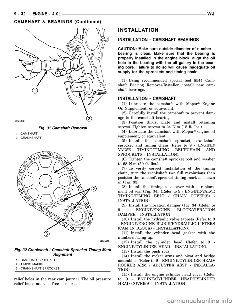
(11) Rotate the crankshaft until the crankshaft
sprocket timing mark is aligned on centerline with
the camshaft sprocket timing mark (Fig. 32).
(12) Remove the timing chain and sprockets (Refer
to 9 - ENGINE/VALVE TIMING/TIMING BELT/
CHAIN AND SPROCKETS - REMOVAL).
(13) Remove the front bumper and/or grille, as
required.
(14) Remove the two thrust plate retaining screws,
thrust plate and camshaft (Fig. 31).
INSPECTION
INSPECTION - CAMSHAFT BEARINGS
(1) Inspect the bearing journals for uneven wear
pattern or finish.
(2) Inspect the bearings for wear.
INSPECTION - CAMSHAFT
(1) Inspect the cam lobes for wear.
(2) Inspect the camshaft position sensor drive gear
for wear.
(3) If the camshaft appears to have been rubbing
against the thrust washer, examine the oil pressure
Fig. 30 CamshaftÐTypical
1 - CAMSHAFT
2 - LOBES
3 - BEARING JOURNAL
WJENGINE - 4.0L 9 - 31
CAMSHAFT & BEARINGS (Continued)
Page 1275 of 2199
relief holes in the rear cam journal. The oil pressure
relief holes must be free of debris.
INSTALLATION
INSTALLATION - CAMSHAFT BEARINGS
CAUTION: Make sure outside diameter of number 1
bearing is clean. Make sure that the bearing is
properly installed in the engine block, align the oil
hole in the bearing with the oil gallery in the bear-
ing bore. Failure to do so will cause inadequate oil
supply for the sprockets and timing chain.
(1) Using recommended special tool 8544 Cam-
shaft Bearing Remover/Installer, install new cam-
shaft bearings.
INSTALLATION - CAMSHAFT
(1) Lubricate the camshaft with MopartEngine
Oil Supplement, or equivalent.
(2) Carefully install the camshaft to prevent dam-
age to the camshaft bearings.
(3) Position thrust plate and install retaining
screws. Tighten screws to 24 N´m (18 ft. lbs.).
(4) Lubricate the camshaft with Mopartengine oil
supplement, or equivalent.
(5) Install the camshaft sprocket, crankshaft
sprocket and timing chain (Refer to 9 - ENGINE/
VALVE TIMING/TIMING BELT/CHAIN AND
SPROCKETS - INSTALLATION).
(6) Tighten the camshaft sprocket bolt and washer
to 68 N´m (50 ft. lbs.).
(7) To verify correct installation of the timing
chain, turn the crankshaft two full revolutions then
position the camshaft sprocket timing mark as shown
in (Fig. 33).
(8) Install the timing case cover with a replace-
ment oil seal (Fig. 34). (Refer to 9 - ENGINE/VALVE
TIMING/TIMING BELT / CHAIN COVER(S) -
INSTALLATION).
(9) Install the vibration damper (Fig. 34) (Refer to
9 - ENGINE/ENGINE BLOCK/VIBRATION
DAMPER - INSTALLATION).
(10) Install the hydraulic valve tappets (Refer to 9
- ENGINE/ENGINE BLOCK/HYDRAULIC LIFTERS
(CAM IN BLOCK) - INSTALLATION).
(11) Install the cylinder head gasket with the
numbers facing up.
(12) Install the cylinder head (Refer to 9 -
ENGINE/CYLINDER HEAD - INSTALLATION).
(13) Install the push rods.
(14) Install the rocker arms and pivot and bridge
assemblies (Refer to 9 - ENGINE/CYLINDER HEAD/
ROCKER ARM / ADJUSTER ASSY - INSTALLA-
TION).
(15) Install the engine cylinder head cover (Refer
to 9 - ENGINE/CYLINDER HEAD/CYLINDER
HEAD COVER(S) - INSTALLATION).
Fig. 31 Camshaft Removal
1 - CAMSHAFT
2 - CRANKSHAFT
Fig. 32 Crankshaft / Camshaft Sprocket Timing Mark
Alignment
1 - CAMSHAFT SPROCKET
2 - TIMING MARKS
3 - CRANKSHAFT SPROCKET
9 - 32 ENGINE - 4.0LWJ
CAMSHAFT & BEARINGS (Continued)